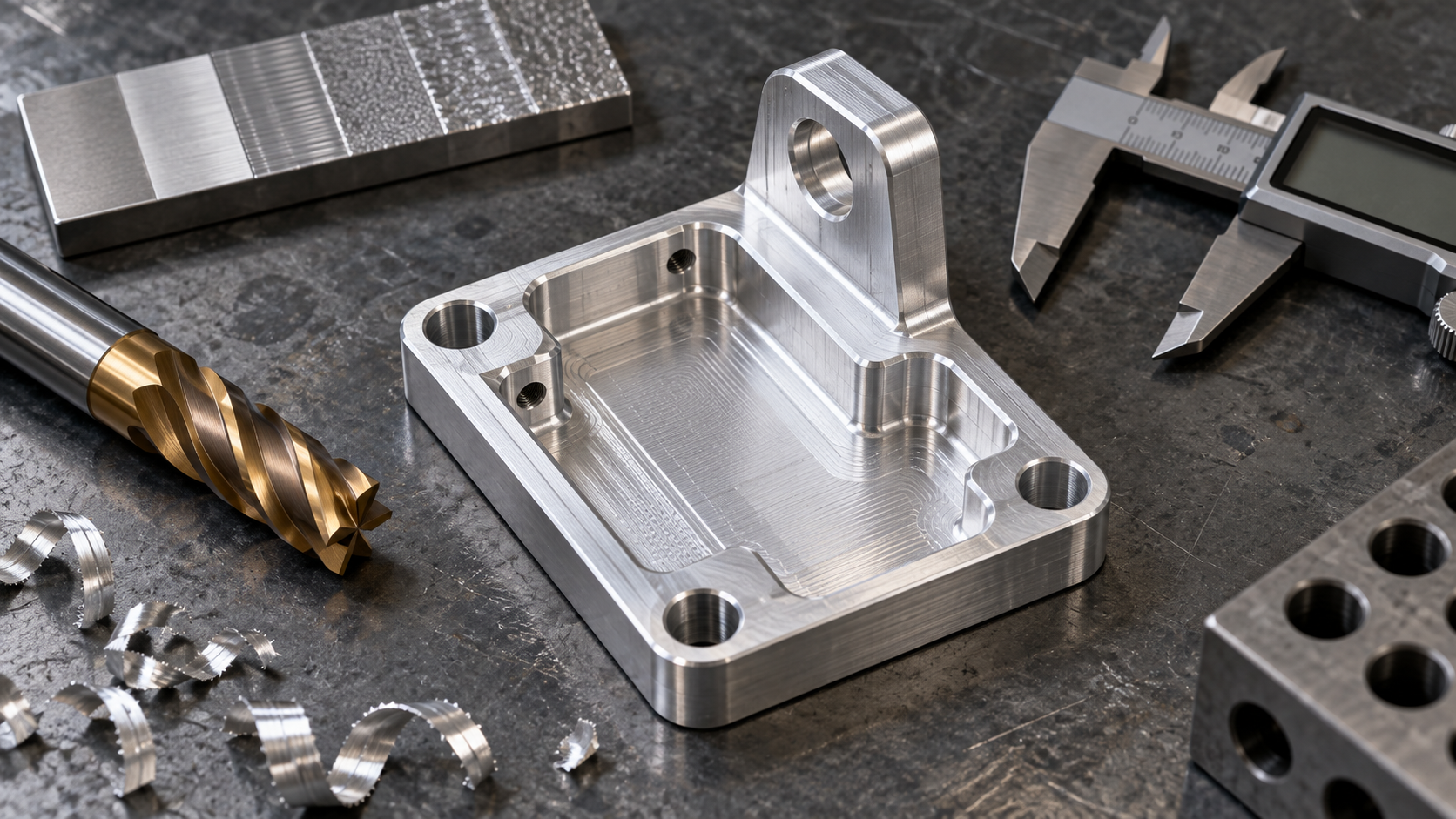
Machining Knowledge Quick Reference: Understand the Precision and Cost of Major Processes in One Table
The essence of machining is controlled material removal. Turning a blank into the part shown on the drawing does not rely on the vague idea of "getting rid of the excess," but on causing a determined relative motion between the tool and the workpiece, cutting material away layer by layer. There are three unavoidable roles here: workpiece, tool, and chip. The relative motion of tool and workpiece is the prerequisite for cutting to occur, and the chip is merely a byproduct of this process—but the shape, color, and breakage of the chip are precisely the first signal on the shop floor for judging whether the parameters are reasonable.
The trouble is that there is more than one way to remove material. Turning, milling, drilling, grinding, EDM, laser, and waterjet each occupy a different position along the dimensions of "what shapes can be machined," "how accurate can it be," "how smooth can the surface be," and "what cost tier does it fall into." No single process is universal: no matter how accurate turning is, it cannot produce a square cavity; laser cuts quickly but has difficulty cutting a true three-dimensional curved surface; grinding offers extremely high precision but is usually only used for final machining.
So when discussing machining knowledge, it is best to first build a global map rather than plunging straight into the details of a single process. The table below compares common processes under the same set of coordinates. It should be noted in advance: the values in the table are typical industry reference ranges, not guaranteed values from any particular company. Actual results depend on the material, tool, machine rigidity, fixturing method, and specific working conditions, and each item still needs to be confirmed individually when it goes onto a drawing.
| Process | Machinable Materials | Typical Tolerance / Precision | Typical Surface Roughness | Cost Level |
|---|---|---|---|---|
| Turning (including CNC turning) | Steel, aluminum, copper, stainless steel, engineering plastics | General IT7~IT8; CNC turning can reach IT6 | Ra0.8~1.6μm | Low—Medium |
| Milling (including CNC milling) | Steel, aluminum, copper, titanium, plastics | General IT7~IT8; fine milling can reach IT6~IT8 | General Ra1.6~6.3μm; fine milling can reach Ra0.63~5μm | Medium |
| Drilling | Almost all machinable materials | Generally only up to IT10 | Ra12.5~6.3μm | Low |
| Grinding | Hardened steel, cemented carbide, glass, granite | Flatness about 0.004~0.008mm; high-precision cylindrical grinding roundness can reach about 0.1μm | Can reach Ra0.8μm or even lower | Medium—High |
| EDM / Wire EDM | Conductive materials, virtually unlimited hardness | Depending on machine model and working conditions, often in the range of ±0.005~±0.02mm | Ra0.4~3.2μm, often with a recast layer | Medium–High |
| Laser Cutting | Carbon steel, stainless steel, alloy steel, copper, aluminum, galvanized sheet | Approximately ±0.02mm (depending on material and thickness) | Cut edge Ra<6.5μm | Medium |
| Waterjet Cutting | Metal, stone, glass, composite materials | Generally ±0.1~±0.25mm | Cut edge is relatively rough, often requires subsequent processing | Medium |
Reading through this table, you will notice two things. First, precision and roughness are not the same thing: drilling has a very wide tolerance band (generally IT10), but its Ra value (12.5~6.3μm) is not the worst; grinding offers extremely high precision and very low roughness, but its cost rises accordingly. Second, cost does not rise linearly with precision, but jumps up a notch at certain points—for example, from "achievable by milling" to "grinding is mandatory," from "achievable with standard tooling" to "EDM corner clearing is mandatory." When selecting a process, what really needs to be judged is which range the requirement falls into and whether it crosses that jump threshold.
Additionally, the positioning accuracy of the machine tool itself is a separate concept. The positional accuracy of modern CNC machine tools is generally between ±0.005mm and ±0.025mm, but this figure describes where the machine can go—it does not mean the part can necessarily achieve that tolerance. The final dimensions of a part also stack up tool wear, thermal deformation, clamping stress, and measurement error. Promising machine tool accuracy as part accuracy is one of the most common misunderstandings in process selection and quoting.
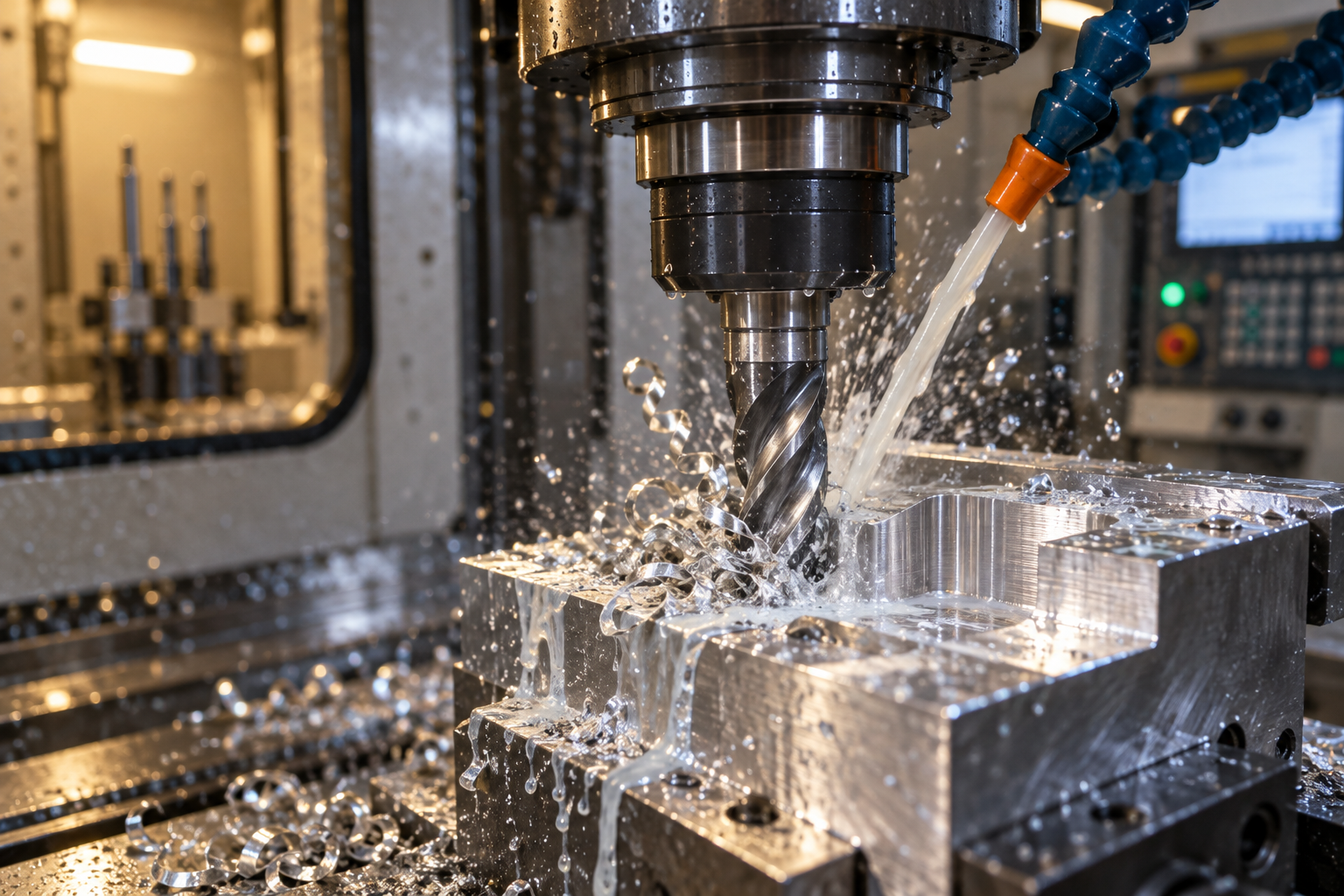
Core knowledge system of machining: materials, equipment and tools, parameters and operations
A quick-reference table can tell you "roughly what can be achieved," but to truly judge whether a part can be machined and whether costs will spiral out of control, you have to return to three layers of things: materials and mechanics, equipment and tools, and parameters and operations. These three layers are not a parallel checklist, but a relationship of layer-by-layer constraints—materials determine whether the tool can hold up, tools determine how fast the equipment can run, and equipment and tools together frame the choices of parameters and fixturing. Memorizing process terms flatly by "turning, milling, drilling, grinding" fails as soon as the material changes; reasoning by these three layers is what makes the basis for judgment stand up.
Materials and mechanics: where machinability differences come from
The same carbide end mill, milling 6061 aluminum alloy versus milling 304 stainless steel, is two different experiences. Aluminum alloy is soft and has good thermal conductivity; during cutting most of the heat is carried away by the chips, so you can run high spindle speeds and large feeds; but it is also highly ductile, and when the rake angle is not sharp enough and chip evacuation is poor, it easily causes built-up edge, with chips welding onto the cutting edge to form a built-up edge, and the surface gets chewed into a patch of burrs. 304 stainless steel has poor thermal conductivity and an obvious tendency toward work hardening; cutting heat concentrates near the cutting edge, tool wear is fast, and too shallow a depth of cut can also "rub" a harder hardened layer onto the machined surface, making the next cut even harder. 45 steel sits in the middle; its hardness varies greatly before and after quenching and tempering—normalized state cuts easily, but after quenching and tempering to 28~32HRC, tool life drops noticeably. As for high-hardness materials such as hardened steel and cemented carbide, conventional tools basically cannot cut them, and usually the process has to shift to grinding or EDM.
So the basis for judgment at the material layer is very simple: first look at hardness, then look at thermal conductivity and work-hardening tendency. Hardness sets the upper limit for tool material and cutting speed; thermal conductivity and hardening tendency set the cooling method and feed strategy. Change the grade on the same drawing and the parameters often have to be readjusted—this is not the operator being arbitrary, but the material speaking.
Equipment and tools: how many axes, what tool, what coating
The equipment layer is often simplified to "three-axis or five-axis," but what actually needs to be asked is how many faces and features can be reached in one setup. Three-axis is suitable for parts with a single base face and features concentrated in one or two directions; four-axis solves drilling on the side of a rotational body and milling flats; the value of five-axis and turn-mill multitasking lies in reducing the number of setups—each additional setup adds one more datum transfer error, and thin-walled parts also have to worry about clamping deformation. The number of setups often determines whether the final tolerance can be held more than the machine tool's nominal accuracy.
The logic for choosing tools is "material matches material." High-speed steel has good toughness and is cheap, suitable for low-speed small-batch work and for drills and taps; cemented carbide is the mainstay of machining, wear-resistant and able to withstand higher linear speeds; ceramics and CBN target high-hardness materials and high-speed finishing, but are brittle and afraid of impact, and place high demands on machine tool rigidity. Coatings address friction and heat: TiN is general-purpose, TiAlN is heat-resistant and suitable for dry cutting or high-speed machining of stainless steel. In terms of geometry, the rake angle determines the sharpness of the cutting edge and the direction of cutting force; a large rake angle is light and quick but the edge is weak; the relief angle determines the friction between the cutting edge and the machined surface; too small a relief angle causes scraping and heat. These angles are not ground at random; they are matched to the material and the operation.
Parameters and operations: how speed, feed, and depth of cut constrain each other
The three elements of cutting—speed, feed, and depth of cut—cannot be adjusted independently. High speed with slow feed makes the cutting edge rub in place, easily burning the tool and causing work hardening; large feed with large depth of cut makes the cutting force exceed the rigidity of the tool or fixture, causing chatter and leaving regular ripples on the surface. The goal of roughing is to remove material as quickly as possible, using a large depth of cut and moderate feed, leaving 0.3~0.5mm of allowance for finishing; the goal of finishing is to control surface and dimensions, with small depth of cut and uniform feed, avoiding the low-to-medium speed range where built-up edge easily occurs. This logic is connected to the materials in the first layer and the tools in the second layer: change the material or change the tool, and the three elements must follow.
Fixturing and datum selection are the most easily underestimated part of this layer. The datum face must be flat and large enough for stable positioning; thin-walled parts clamp too tightly and spring back, too loosely and they chatter. Many "out-of-tolerance after machining" problems have their root cause not in the tool or the parameters, but in the fixturing method allowing the part to move under cutting force.
Characteristics and applicable scenarios of common machining processes: turning, milling, drilling, and grinding broken down item by item
Turning: the home turf of rotational parts
Milling: flat surfaces, grooves, cavities, and complex contours
Drilling: The starting point of hole machining, not the end point
Grinding: The finishing method for high precision and hard materials

Special machining and cutting processes: The boundaries of EDM, laser, waterjet, and wire cutting
The turning, milling, drilling, and grinding discussed in the previous section all rely on tool cutting edges to "gnaw" at the material, and the tool must be harder than the workpiece. But in reality, there is a class of parts that are too hard for the tool to gnaw through, or whose shapes are too awkward for the tool to reach—hardened steel molds, narrow slot corner cleaning, deep cavity sharp corners. At this point, what comes into play is not a stronger tool, but special machining that switches to a different material removal principle. The key to understanding them is to grasp what energy each relies on to remove material, and what "aftereffects" that energy leaves behind.
EDM and wire cutting: Not limited by hardness, but leaving a recast layer
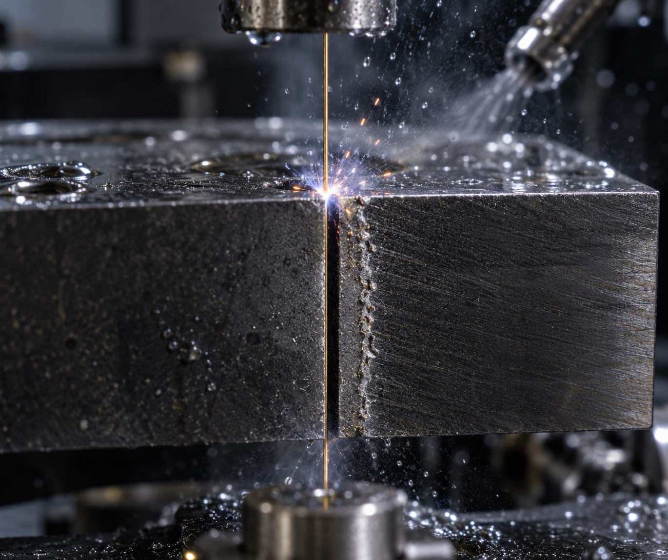
Electrical discharge machining (EDM) and wire EDM (WEDM) use the same principle: causing controlled pulsed discharges between an electrode and the workpiece, using instantaneous high temperatures to erode material bit by bit. The electrode does not contact the workpiece, so it is almost unlimited by material hardness—hardened steel and cemented carbide can both be machined, which tool machining cannot achieve. Wire EDM uses a thin metal wire as the electrode, making it particularly suitable for cutting narrow slots, corner cleaning, irregular through holes, and those internal right angles in molds (where the tool radius cannot reach).
There are two costs. First, discharge erosion is a thermal process, and the machined surface forms a recast layer (remelted layer) whose properties differ from the substrate, and which often must be removed for precision or fatigue-critical parts. Second, material is "burned" away bit by bit, so efficiency is significantly lower than milling, and it is typically used only for locations the tool cannot reach or where hardness exceeds limits, rather than for large-area roughing. If grinding or polishing follows, this layer's allowance must be factored in.
Laser cutting: A sharp tool for thin plates; for thick plates, examine the cut face
Laser cutting uses a high-energy-density beam to melt or vaporize material, with a narrow kerf and high speed. Commonly cited industry capabilities are roughly: cutting accuracy of approximately ±0.02mm, cut surface roughness Ra<6.5μm, capable of cutting carbon steel, stainless steel, alloy steel, copper, aluminum, galvanized sheet, etc. These are typical references; actual results depend on material, plate thickness, equipment, and process parameters.
Its boundaries are also clear: the thicker the plate, the harder it is to guarantee cut face quality. Thick plate cut faces are prone to taper (wider at top, narrower at bottom) and dross at the bottom, often requiring secondary dross removal or switching to another process. Therefore, laser cutting is better suited for thin plate blanking, hole making, and outer contour profiling—"cutting" large numbers of small parts from a full sheet as a preceding operation for subsequent bending, welding, and machining.
Waterjet: The Trade-off Between Cold Cutting and Heat-Affected Zone
Waterjet (abrasive waterjet) uses high-pressure water mixed with abrasive to erode material. Its most prominent advantage is cold cutting—no heat input, and therefore no heat-affected zone; the material won't anneal or deform. This makes it especially suitable for heat-sensitive materials (certain plastics, composites) and thick plates that cannot be exposed to heat. It is also almost indifferent to material hardness.
Two things must be weighed: the cut has a taper (the jet spreads from top to bottom), which is not friendly to tight-fitting holes; and abrasive consumption and operating costs are relatively high, with speed also slower than laser. So waterjet often appears in scenarios of "afraid of heat + need to cut thick," rather than being used for all cutting jobs.
Connecting this section with the previous ones: conventional tooling processes handle the vast majority of parts with regular shapes and machinable materials; special processes specifically fill the gaps where tools can't reach, materials can't be cut, or heat can't be tolerated. When selecting, first ask "can this feature be made with a tool"—if it can, prioritize the tool, because it's faster, cheaper, and the surface is more controllable; if it can't, then refer to the three boundaries above to choose a special process. The next section integrates these judgments into a complete process selection framework.
How to Choose the Most Suitable Machining Process Based on Product Requirements
Material Properties: Filter First by Hardness, Toughness, and Thermal Conductivity
Dimensional Accuracy and Surface Finish: Tolerance Band Determines Whether to Change Processes
Production Volume and Cost: Prototyping, Small Batch, and Mass Production Take Three Paths
Geometric Complexity and Feature Accessibility: Can the Tool Reach It
From Design to Verification: A Complete Machining Workflow for an Aluminum Mounting Bracket
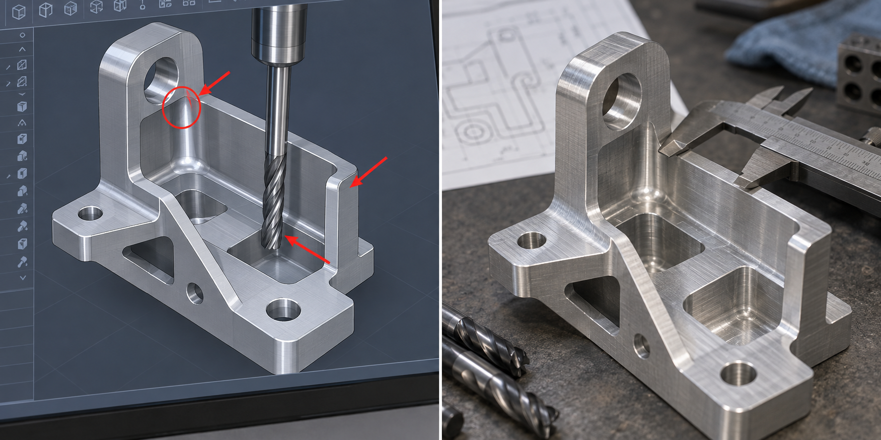
The previous sections broke machining knowledge into processes, parameters, and selection. But real parts aren't made chapter by chapter—they start from a sketch, and every decision in between either digs a pit or paves the way for the steps that follow. This section uses a specific part to connect the whole chain: a 120×80×10mm aluminum mounting bracket, 6061-T6, critical hole tolerance ±0.05mm, mating surface Ra1.6μm. It was chosen because this kind of part is common enough—a plate, four mounting holes, two locating holes, one stiffening rib, one internal pocket—so common that almost anyone doing machining will encounter it, and the pitfalls it hits are typical enough.
Design phase: establish the datum surface and internal corner radii first
The design phase doesn't touch the machine tool, but it determines the difficulty of every subsequent operation. The first thing is establishing the datum: this bracket uses the 120×80 bottom face as the primary datum, with two φ6H7 round holes as locating holes, spaced 90±0.05mm apart. Why two round holes instead of one round hole and one slot? Because round holes paired with cylindrical pins can simultaneously constrain translation in two directions, making the datum clearer; it's also easier to align during subsequent CMM measurement.
The second thing is internal corner radii. The four corners of the bracket's internal pocket were initially drawn as right angles—this looks clean on the drawing, but in milling it means EDM corner clearing is required, and the cost jumps a tier. After changing to R3, a single φ6 end mill can complete the internal contour without changing processes. R3 wasn't filled in arbitrarily: it must be larger than the tool radius (φ6 tool radius is 3mm), while being smaller than the wall thickness (10mm) to retain sufficient rigidity. The reasoning behind this will be expanded in the DFM section later.
Programming phase: tool selection, toolpath sequencing, roughing and finishing separated
Programming is the step that connects geometry and parameters. The toolpath for this part roughly divides into three tools: a φ12 end mill for the outer profile and top face roughing, a φ6 end mill for clearing the internal pocket and stiffening rib sides, and a φ6 or φ5.5 drill paired with a reamer for the locating holes. The goal of roughing is efficient material removal; the goal of finishing is dimensions and surface quality.
Roughing parameters can reference a magnitude like this: spindle speed around 12000rpm, feed around 2500mm/min, axial depth of cut around 3mm (for aluminum, carbide end mills, and sufficient machine rigidity; actual values vary with tool grade, overhang length, and cooling method, and must be verified by test cuts or toolpath simulation). During finishing, reduce depth of cut to 0.3~0.5mm, appropriately increase feed, and maintain speed, with the aim of keeping cutting forces stable and avoiding tool deflection. The core logic of separating roughing and finishing is: roughing allows large cutting forces, but doesn't allow leaving stock arbitrarily; the success of finishing depends on how much stock roughing left and how evenly it was left.
Machining phase: fixturing, stock allowance, thermal deformation, and tool deflection
The fixturing plan determines whether the part can be machined to drawing tolerances. This bracket is clamped on the two 10mm-thick sides with a bench vise, exposing the top face and internal pocket; the bottom face is machined last after flipping (rechucking). When flipping, the two already-machined locating holes are used as the datum rather than re-edge-finding—this is the key to ensuring the ±0.05mm hole spacing. If both setups rely on vise jaw alignment, cumulative error can easily consume half the tolerance.
A 10mm-thick aluminum plate isn't considered thin during finishing, but near the stiffening rib there is only about a 6mm vertical wall, which will have slight chatter during milling. The experienced approach is to reduce radial width of cut and increase speed when finishing the sides, directing cutting forces toward directions with better rigidity. Thermal deformation has little effect at this size, but if multiple parts are machined continuously, aluminum chips accumulate, and coolant temperature rises, dimensions will slowly drift—so inspecting the first part and then sampling one more in the middle of the batch is meaningful.
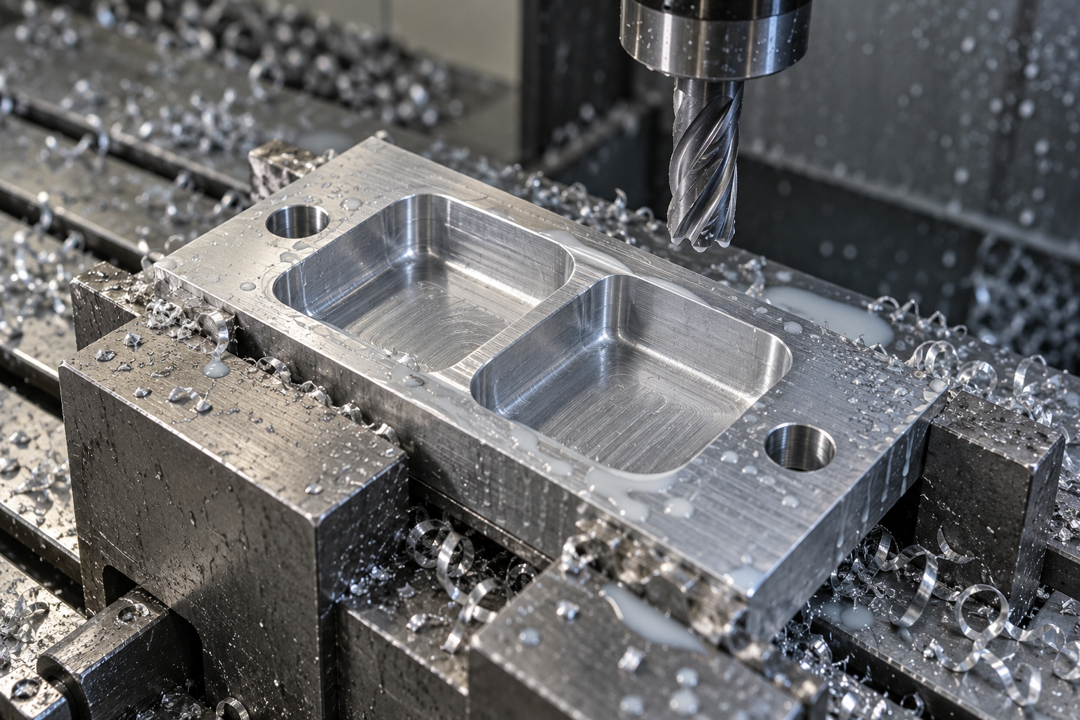
Verification phase: from calipers to CMM, each checks different things
Verification isn't just a final formality; it's bringing out the assumptions from every previous step and reconciling them. Basic dimensions (outer length and width, thickness, hole positions) can be covered with calipers and micrometers; the diameter and roundness of locating holes require an inside micrometer or plug gauge; the ±0.05mm hole spacing and mating surface flatness rely on a coordinate measuring machine, or full-dimensional comparison using 3D scanning—the value of 3D scanning here is that it can capture a deviation contour map of an entire surface at once, making it faster than point-by-point measurement to discover trend deviations (such as one side warping or hole positions shifting overall).
Surface roughness Ra1.6μm can be spot-checked on the mating surface with a portable roughness tester. One reminder: Ra and dimensional tolerance are two separate sets of specifications. A part with all dimensions correct but tool marks on the surface, or a bright surface but out-of-tolerance hole spacing, are common acceptance disagreement points, and both must be specified separately on the drawing.
The most easily underestimated thing in the entire process is the interdependence between stages: the R3 set in the design phase determines that programming can choose a φ6 tool, the rigidity of the φ6 tool determines the upper limit of finishing depth of cut, depth of cut affects surface roughness, and roughness ultimately determines whether a roughness tester is needed during verification. Conversely, if verification finds hole spacing out of tolerance, tracing upward may reveal that the datum wasn't unified during flip fixturing, rather than insufficient machine accuracy—this kind of judgment is precisely the most practical part of machining knowledge.
Design for manufacturing: control cost before the first cut
For the aluminum mounting bracket above, ask the question differently: when was its cost determined? Not at the moment the spindle started, but when the designer drew the first internal right angle in CAD. Design for manufacturing (DFM) is about exactly this—injecting production knowledge into the design phase in advance, finding the root cause of cost before the first cut. Once the drawing is frozen, the program is written, and the blank is cut, many structural problems are already hard to change—either pay more, reduce functionality, or accept rework. So the most cost-saving part of machining knowledge is precisely those few dozen minutes before getting on the machine.
Internal corner radii and tool radii must match
End mills are round; they cannot mill a true internal right angle. If the four internal corners of a pocket are specified as R0, EDM or a dedicated corner-clearing process is required, and both operations and labor hours jump. A common industry practice is to specify internal corner radii slightly larger than the tool radius to be used; for example, if planning to use a φ6 tool, specify internal corners as R3.2 or larger so the tool can smoothly complete the contour. If not changed: either an extra process step is added, or the designer is forced to accept the small arc left by the tool in the corner, only to find during assembly that the mating part won't fit.
Wall thickness, deep pockets, and tool accessibility
- Keep wall thickness as uniform as possible. Thin walls will chatter under cutting forces and are prone to deformation from residual stress release, causing dimensions to drift after finishing. If not changed: dimensions pass on the machine but go out of tolerance after cooling off the machine.
- For deep pockets, consider the length-to-diameter ratio. The longer the tool extends, the worse its rigidity; the bottom and side walls of deep pockets are prone to tool deflection and worse surface roughness. Industry usually recommends controlling the ratio of depth to tool diameter within a reasonable range; if exceeded, step down in layers or switch to a thicker tool. If not changed: either frequent tool changes, or surface roughness fails to meet drawing requirements.
- Threaded holes need sufficient pre-drill depth. If the pilot hole is too shallow, the tap will bottom out and may even break. If not changed: tapping is scrapped, and the part may be scrapped along with it.
Reduce the number of setups and unify the datum
Every re-fixturing introduces a positioning error. Arrange multiple faces and multiple holes to be completed in a single setup, or design them to share the same datum surface from the start—accuracy is easier to hold and machining time is saved. Conversely, if a part has to be fixtured once on each of three machines, cumulative error and handling time will both increase. What happens if you don't change it: the relative positions of the holes go out of tolerance, and assembly relies on hand-fitting to force things together.
Don't over-specify tolerances
Writing ±0.02mm casually on a drawing looks rigorous, but in practice it may force an ordinary milled part into a ground part. There is a plain rule of thumb in machining knowledge: every time the tolerance band is tightened by one grade, it often means changing the process, changing the inspection gauge, and adding cost. Tighten only where it is truly needed—mating surfaces, locating holes, sealing surfaces; set the rest according to function. What happens if you don't change it: quotes come back inflated, or the supplier simply says it can't be made.
The common logic behind these checkpoints is: one stroke at the design stage determines the direction of the dozens of subsequent operations. DFM is not about adding restrictions to designers, but about letting them make choices while costs are still low. If you want to go through these items one by one for a specific part, you can learn about typical process ranges from the CNC machining capabilities page, then discuss your drawing.
Machining knowledge FAQ
The following questions are the ones most often asked after reading the preceding content. The answers all come with qualifications—for a specific part, you still need to look at the drawing, material, and machine condition.
For the same part, should you choose machining or 3D printing?
Look at two things first: whether the material can be printed, and whether the accuracy is sufficient. 3D printing (FDM/SLA/SLS/MJF/DMLS) is suitable for complex internal cavities, lightweight structures, rapid prototyping, and small-batch trial production, but anisotropy, layer lines, and surface roughness are inherent characteristics; machining is subtractive, and material density and dimensional stability are usually better, making it easier to tighten the tolerance band. The basis for judgment: if the part is a load-bearing part, has mating surfaces, has threads, or requires a surface below Ra1.6μm, generally prioritize machining; if the structure is so complex that the tool cannot reach inside, or you only need a few dozen pieces to verify the shape, 3D printing is more cost-effective. The two can also be combined—print a blank and then finish-machine the critical surfaces.
The drawing specifies ±0.05mm—is tighter tolerance always better?
No. Narrowing the tolerance band means changing the process, increasing the number of setups, or switching to grinding, and both cost and gauge requirements will jump. ±0.05mm is achievable for conventional mating surfaces in CNC milling, but it depends on whether the datums are unified, whether the part has enough rigidity, and whether there are thin walls. What you should really do is allocate tolerances by function: tighten mating surfaces and loosen non-mating surfaces. If the entire drawing is uniformly marked ±0.05mm, the shop often has no choice but to plan the process according to the tightest grade, and the extra cost does not buy any functional improvement. It is recommended to mark which dimensions are critical dimensions on the drawing and treat the rest as general tolerances.
Why can't drilling be used directly as a finishing operation?
The accuracy of drilling generally only reaches about IT10, with surface roughness of about Ra12.5~6.3μm, and the drill bit has limited rigidity and tends to wander, so the straightness and position accuracy of the hole are unstable. Therefore, drilling is usually used as the roughing or pre-machining of a hole, followed by reaming, reaming, or boring for semi-finishing and finishing to obtain a hole of IT7~IT8 or even tighter. If the drawing has high mating requirements for the hole, simply writing "drilled" on the drawing is not enough; the subsequent operations and final dimensions must be specified.
Are surface roughness Ra and dimensional tolerance the same thing?
No. Tolerance governs which interval the dimension falls into, while Ra governs the arithmetic mean deviation of the microscopic surface irregularities, and the two are determined by different factors. A part with a very loose dimensional tolerance may have a very rough surface; conversely, a ground surface can have an Ra of 0.8μm or even lower, but the dimensional tolerance still has to be controlled separately. In actual machining they constrain each other—fine milling can improve both dimension and surface at the same time, but grinding is the conventional means of pressing Ra below 0.4μm. Both must be specified on the drawing; you cannot specify only one.
For a small batch of a few dozen pieces, how should the process route be determined?
The core contradiction in small-batch production is "whether the mold cost can be amortized." Injection molding requires a mold, and for a few dozen pieces the per-piece cost after amortization is very high unless there is an expectation of mass production later; hand lay-up replica molding (vacuum casting) is suitable for a few dozen pieces, appearance and assembly verification; CNC machining requires no mold, and changing the design only requires changing the program, making it suitable for structural parts and functional parts; sheet metal is suitable for panel-type enclosures and brackets. The general order of judgment is: first see whether the material and structure can be made by subtractive methods, then see whether the batch is large enough to be worth opening a mold. For which route to choose specifically, it is recommended to give the drawing and quantity together to the machining provider for a process evaluation, rather than looking only at the unit price.
Key takeaways
- The essence of machining is controlled material removal, and the three elements are always the workpiece, the tool, and the chip; the relative motion between tool and workpiece is the prerequisite for cutting.
- Turning, milling, drilling, grinding, EDM, laser, and waterjet each have their own precision and cost boundaries. There is no "universal process"—drilling generally only reaches IT10, while grinding is used for high precision and hard materials.
- Selection must consider both technical feasibility and economic viability: material properties, dimensional precision and surface finish, production volume and cost, and geometric complexity and tool accessibility.
- Higher precision is not always better. Tightening the tolerance band by one grade often means changing operations, changing setups, or adding inspection gauges, and the cost jumps accordingly.
- The design stage (DFM) determines most manufacturability and cost. Internal corner radii, wall thickness uniformity, pre-drilled depth for threaded holes, and tool accessibility are common checkpoints.



