What a ferrofluid sealing device is: starting from the "liquid O-ring"
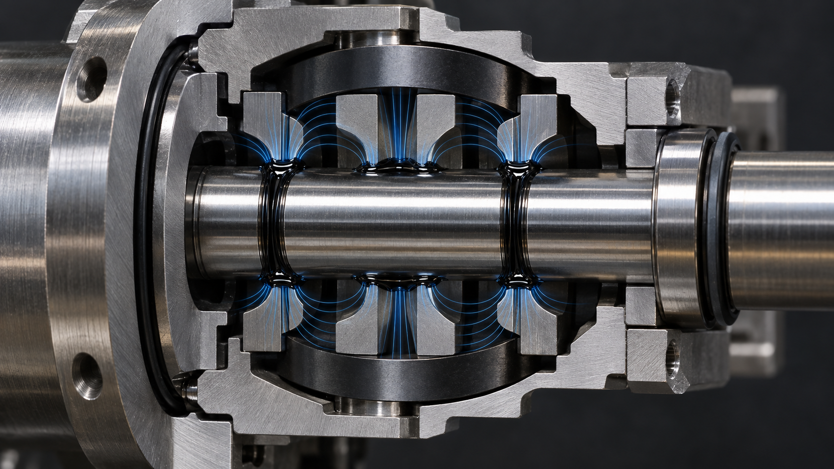
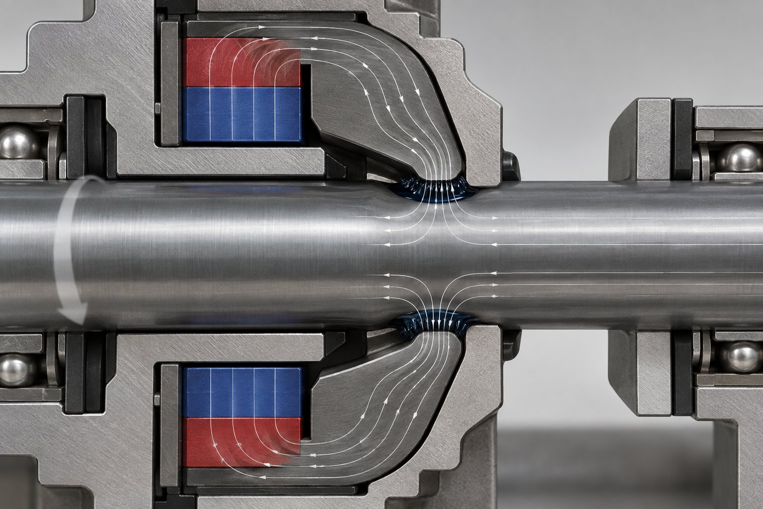
A ferrofluid sealing device is a dynamic seal that uses a magnetic field to "pin" magnetic liquid in a rotating gap. The structure is not complicated: a permanent magnet provides magnetomotive force, pole teeth on both sides concentrate magnetic flux onto the shaft surface, and the shaft itself is a segment of the magnetic circuit; the ferrofluid is attracted beneath the pole teeth, forming a ring of liquid equivalent to an O-ring that never wears out.
Its fundamental difference from lip seals and mechanical seals lies in the contact method. The latter two rely on solid-to-solid (or solid-to-shaft) compression to block the medium, bringing friction, wear, and wear particles along with it; a ferrofluid sealing device relies on liquid and a magnetic field to block the pressure differential, so the shaft can rotate freely without generating wear particles. Low friction, high-speed capability, and low particle contamination are all different facets of this one mechanism.
How the magnetic circuit works: the coordination of magnet, pole teeth, shaft, and ferrofluid
The sealing capability of a ferrofluid sealing device does not come from rubber compression, but from a ring of magnetic liquid pinned by a magnetic field. The permanent magnet provides magnetomotive force, and the pole teeth concentrate magnetic flux into the narrow gap between them and the shaft; the shaft itself is a segment of the circuit, and the smaller the gap, the higher the magnetic flux density under the same magnetomotive force, and the more firmly the magnetic liquid is held.
The magnetic liquid gathers into a liquid ring beneath each pole tooth, shaped approximately like an O-ring, and the pressure differential across it is resisted jointly by magnetic force, surface tension, and the saturation magnetization of the ferrofluid itself. Multiple pole teeth mean multiple liquid rings, which is also the basis for the pressure-resistance ladder discussed in the next section. The amount of ferrofluid injected should just fill the gap while leaving a meniscus; too little will not seal, and too much will be thrown off or migrate when the shaft rotates.
Single-stage vs. multi-stage: where the pressure resistance of a ferrofluid sealing device comes from
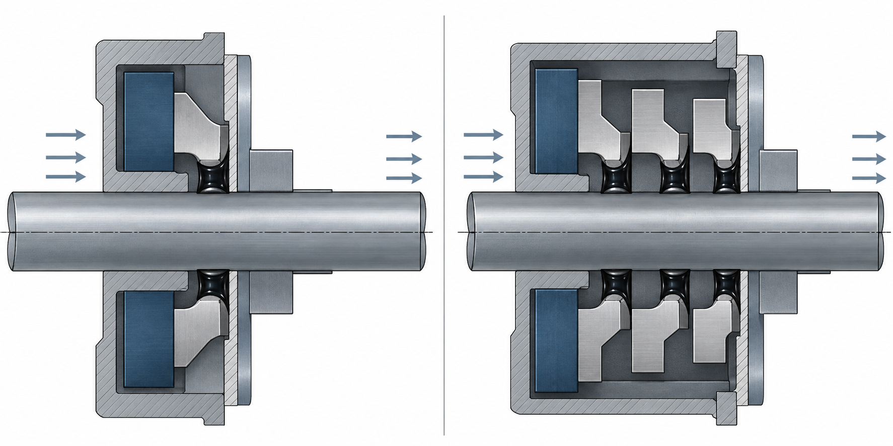
A single-stage ferrofluid sealing device forms one liquid ring beneath one pole tooth, and the magnetic pressure differential across this ring resists the external pressure. A common industry order of magnitude: single-stage pressure resistance is about 0.15–0.2 atmospheres. Once stages are stacked, the pressure is distributed across each ring, and multiple stages in series can achieve on the order of about 2.5 atmospheres. The leakage rate on the vacuum side can reach the order of 10⁻¹² Pa·m³/s, and the vacuum level can reach the order of 10⁻⁶ Pa—the specific values vary with the gap, ferrofluid grade, and operating conditions, and must be confirmed on the drawings.
More stages are not always better
Each added stage requires the shaft to be correspondingly longer, the shear area between the ferrofluid and the shaft wall increases, and damping and heat generation rise along with it. This is especially obvious on high-speed shafts: the pressure resistance gained from multiple stages may be offset by temperature rise and friction power loss. The common order of trade-offs is—first determine the vacuum level and pressure differential, then determine the rotational speed, and finally go back and check the number of stages; if it is still insufficient, use two-stage series structures placed separately rather than piling everything onto one shaft.
Zero leakage, no wear, low friction: four results brought by the same mechanism
Ferrofluid sealing devices are often listed with four selling points: zero leakage, no wear, low friction, and high-speed capability. They are actually different cross-sections of the same causal chain—the ferrofluid forms a liquid O-ring between the pole teeth and the shaft, maintains its position by magnetic force, and does not make solid contact with the shaft. Without solid contact, there is no wear, and therefore no wear particles entering the vacuum chamber.
How no wear leads to low particle contamination
Lip seals and mechanical seals fit against the shaft surface by preload, and the longer they run, the more wear particles are produced, making particle contamination harder to control. A ferrofluid sealing device has no such contact layer, and the sealing medium itself is not consumed or discharged. For chambers that are sensitive to particles, such as coating, ion implantation, and monocrystalline silicon furnaces, this is the main reason it is selected.
The boundaries of low damping and high-speed rotation
The liquid ring provides only shear resistance, with no startup friction peak, so there is no stick-slip at low speed and no uncontrolled heat generation at high speed. The source gives a maximum rotational speed of about 120,000 r/min, which is an upper-order magnitude, not a universal guaranteed value—how fast it can actually run depends on shaft diameter, number of stages, ferrofluid viscosity, and heat dissipation conditions. As for long life, the source mentions that under typical operating conditions it can be used for about 10 years without maintenance, provided the ferrofluid does not volatilize or leak away, and the operating temperature and solvent atmosphere on the vacuum side must be confirmed.
Solid shaft, hollow shaft, and multi-shaft: structural selection of ferrofluid sealing devices
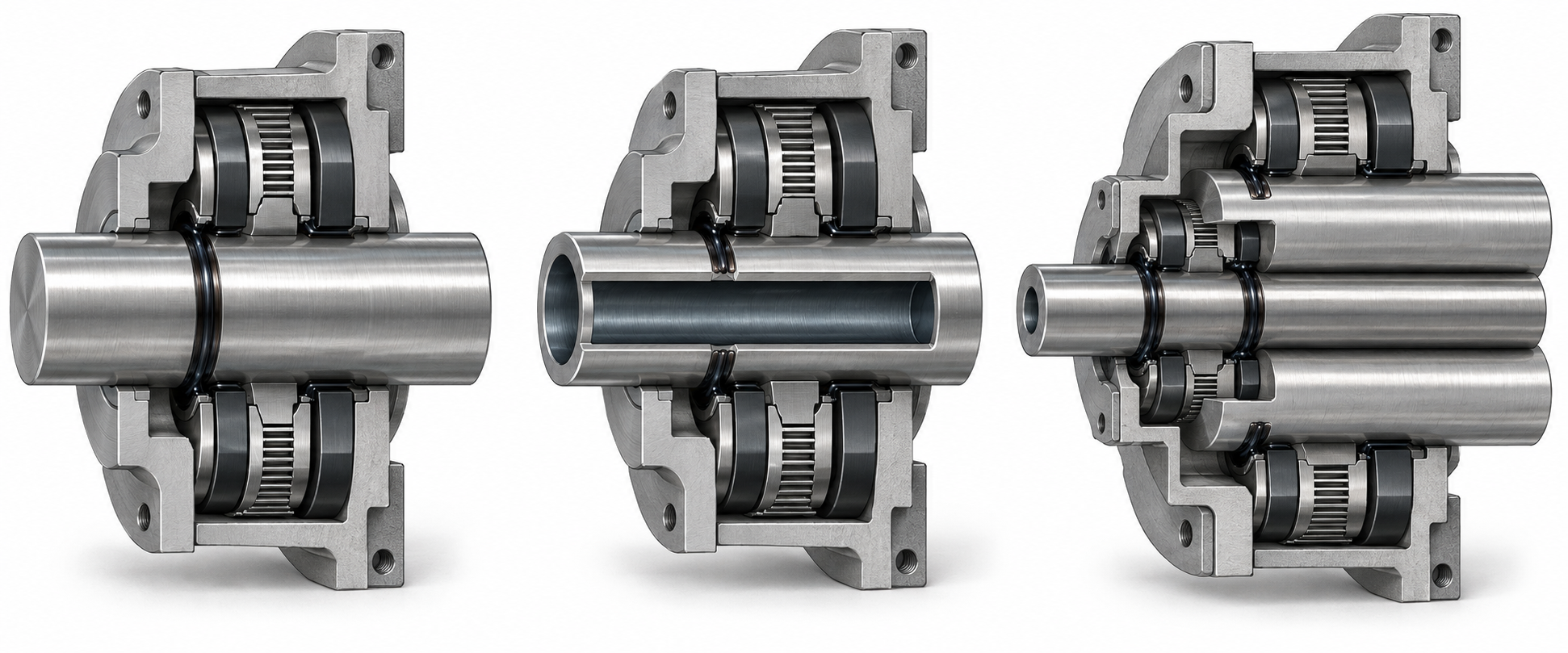
Shaft type is the first branch point in selection. Solid shafts are the most widely used, with a simple structure, good rigidity, and easy gap control; hollow shafts are used for routing wires, gas, or coolant through the shaft, and are common in coating stages and rotating targets for ion implantation; concentric multi-shafts provide multiple independent rotating passages on a single piece of equipment. Ferrotec's product line is basically organized around these three categories, and patent CN204387332U also describes the rotating shaft, housing, pole teeth, and annular grooves as the basic structure.
Decision order: vacuum level, rotational speed, temperature, shaft type, interface
First determine the vacuum level and leakage rate requirements, then determine the rotational speed and continuous operating conditions, then look at temperature and whether a cooling water circuit is needed; shaft type comes after this step—the gap tolerances, runout, and coaxiality of hollow shafts and multi-shafts are more sensitive than those of solid shafts, so the allowable runout and fitting dimensions must be clearly marked on the drawings. Only at the end come the interface flange, gas path, and motor integration method.
If the equipment integrates the motor, encoder, and seal into a single rotary feedthrough, the motor heat generation and the ferrofluid operating temperature must be calculated together during selection; whether the cooling water circuit is integrated often determines whether it can run at high speed for a long time. Once these parameters are set, discussing the structure is easier than choosing a model first.
Frequently asked questions
The following questions are most commonly asked about the structure, pressure resistance, and selection of ferrofluid sealing devices.
What is the most fundamental difference between a ferrofluid sealing device and lip seals or mechanical seals?
It has no solid contact. The magnetic fluid is held by the magnetic field in the gap between the pole teeth and the shaft, forming a ring-shaped "liquid O-ring seal" that uses magnetic force to resist pressure differentials. Lip seals rely on a rubber lip pressing against the shaft surface, and mechanical seals rely on face-to-face contact; both involve friction and wear. The magnetic fluid sealing device eliminates the wear factor, at the cost that pressure resistance depends on stacking stages, and the capability of a single stage is limited.
When the pressure resistance of a single stage is insufficient, can you simply add more stages?
Adding stages can indeed increase pressure resistance. In the industry, a single stage is commonly about 0.15–0.2 atm, and multiple stages in series can reach on the order of about 2.5 atm. However, increasing the number of stages lengthens the shaft and increases frictional damping and heat generation, so a re-evaluation is needed under high-speed conditions. The specific number of stages must be confirmed on the drawing in combination with vacuum level, rotational speed, and allowable temperature rise.
Why are hollow shafts and multi-shaft structures harder to make than solid shafts?
A hollow shaft needs to route wires, gas, or coolant, and its thin wall reduces rigidity; a concentric multi-shaft design requires arranging multiple sets of magnetic circuits within the same housing, making gap control more sensitive. When selecting a model, first determine the shaft type, then mark runout and coaxiality requirements on the drawing. These two items directly determine whether the magnetic fluid ring can stably form a ring.
Are zero leakage, no wear, low friction, and high-speed capability four different things?
They are different aspects of the same mechanism. Because there is no solid contact, there is no wear, no wear debris, and low particle contamination; because friction is low, damping is small and high speed is possible. The upper speed limit given by the source is about 120000 r/min, which is an upper limit rather than a general guaranteed value. The premise of long life is that under typical operating conditions the magnetic fluid does not volatilize or be lost.
Which equipment scenarios are suitable for magnetic fluid sealing devices?
They are concentrated in equipment sensitive to contamination and downtime, such as semiconductors, coating, CVD, monocrystalline silicon furnaces, and liquid crystal regeneration. In these scenarios, the vacuum level can reach on the order of 10⁻⁶ Pa, and the leakage rate can be as low as on the order of 10⁻¹² Pa·m³/s. If the operating temperature, rotational speed, or medium exceeds the conventional range, it is recommended to provide parameters for further discussion.
Key takeaways
- The essence of a ferrofluid sealing device is to use a magnetic field to fix magnetic liquid in the gap; it is a non-contact dynamic seal, not a compression-type mechanical seal.
- Pressure resistance is built up by stacking stages: a single stage is typically about 0.15–0.2 atmospheres, and multiple stages in series can reach on the order of about 2.5 atmospheres; the specific value should be confirmed according to the operating conditions and drawings.
- Zero leakage, no wear, low friction, and high-speed capability are different facets of the same mechanism—without solid contact, there are no wear particles or particle contamination.
- Selection starts by determining the shaft type (solid shaft/hollow shaft/multi-shaft) and whether the motor is integrated, then checking vacuum level, rotational speed, temperature, and cooling requirements, and only then discussing interface dimensions.



