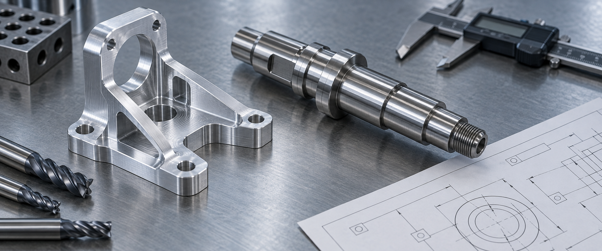
What are the common methods of machined part manufacturing: casting, forging, machining, welding, heat treatment
Machined part manufacturing is a controlled set of processes that turns raw material into qualified parts. Casting, forging, machining, welding, and heat treatment all belong to this set, and machining is only one subset of it—it achieves dimensional and geometric requirements through controlled material removal, whereas casting and forging rely on material forming, welding relies on joining, and heat treatment relies on changing the material's internal structure. Lumping these categories together easily leads to detours in selection: a part that clearly should use a casting for a complex internal cavity is instead milled out of a solid block, which is uneconomical in both cost and lead time.
Casting: the first choice for complex internal cavities and high-volume forming
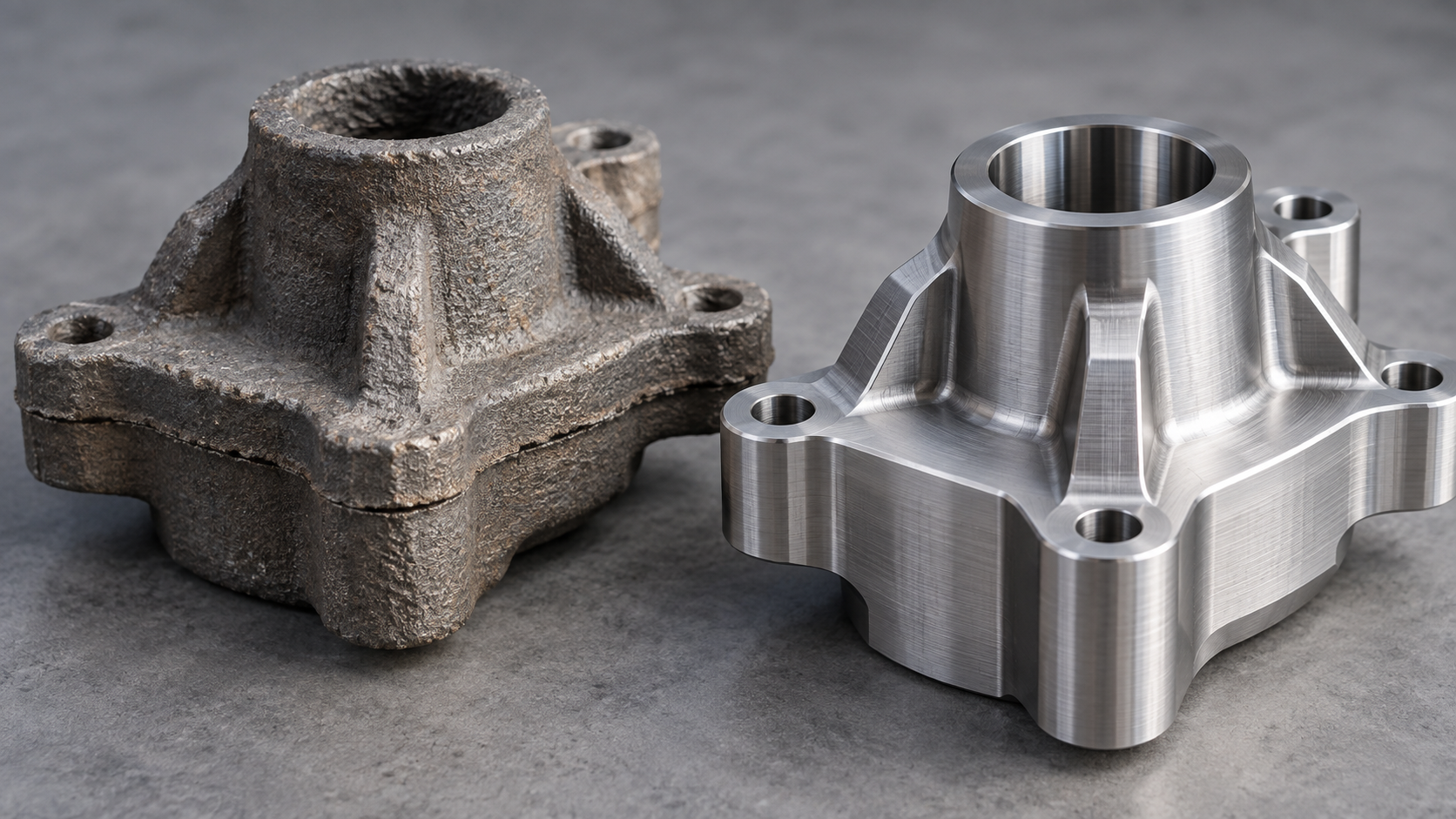
Casting is pouring molten metal into a mold cavity and obtaining a blank or finished product after cooling. Sand casting has the widest adaptability and can handle everything from one-offs to small batches, suitable for parts such as housings, brackets, and large bases that are not complex in shape but are large in volume; die casting is suitable for thin-walled aluminum and zinc alloy parts, and the larger the batch, the more cost advantage per piece, but the mold cost must be amortized first; investment casting offers higher precision and is suitable for parts such as turbine blades and precision valve bodies where details are difficult to guarantee with sand molds. The common advantage of casting is the ability to form internal cavities and irregular outer contours in one go; the disadvantage is that dimensional accuracy and surface quality are usually inferior to machining, and critical mating surfaces often still require allowance for subsequent finishing.
Forging: the trade-off between load-bearing parts and fiber flow lines
Forging uses pressure to form metal and is divided into open-die forging and closed-die forging. Open-die forging is suitable for large-size, small-batch shaft and flange parts, with flexible equipment but large allowances; closed-die forging offers good dimensional consistency and is suitable for batch load-bearing parts such as connecting rods, gear blanks, and steering knuckles. The value of forging lies in the continuous distribution of metal fiber flow lines along the part contour, giving strength and fatigue resistance usually superior to parts cut directly from bar stock. The cost is mold investment and subsequent machining volume—forgings generally require machining allowance, and critical surfaces are ensured by milling or grinding.
Machining: controlled material removal, with clear advantages in precision and small batches
Machining removes material through turning, milling, drilling, grinding, and other methods to bring a blank to drawing dimensions. Its strengths are precision and flexibility: no mold is needed, and changing the program changes the shape, making it very suitable for small batches and rapid prototyping. Examples of suitable parts: aluminum alloy mounting plates, stainless steel shaft sleeves, engineering plastic gear blanks. In the industry, precision machining tolerances are often achieved on the order of 0.01 mm, but the specific level achievable depends on the material, part size, fixturing method, and tool condition, and must be confirmed item by item with the drawing and the processor—it cannot be generalized.
Welding and heat treatment: the division of labor between joining and modification
Welding joins separate parts into a whole, suitable for structural parts such as frames, housings, and piping, with the advantage of saving material and making use of standard profiles. Note that welding heat input causes deformation and residual stress, especially in thin-plate parts, and post-weld straightening or stress relief is often required. Heat treatment does not change the part shape, only the material properties: annealing lowers hardness to facilitate subsequent machining, quenching plus tempering increases strength, and normalizing and tempering achieve comprehensive mechanical properties. Specific process parameters must be determined according to the material grade and performance requirements; for the same material with different cross-sectional sizes, holding time and cooling method may both differ.
These five method categories rarely appear alone on an actual part. A reducer housing may be a cast blank, undergo heat treatment for stress relief, then have its bearing bores and mating surfaces machined, with a welded flange added locally. Understanding what each method is good at and not good at is the basis for later selection decisions. If you have a drawing and want to check manufacturability first, you can use AI chat quoting to submit key dimensions and materials, which is easier than waiting for the quote to come back only to find the process won't work.
How machining is classified by motion type: turning, milling, drilling, grinding, planing
Workpiece rotation: turning handles bodies of revolution
Tool rotation: milling and drilling handle planes, slots, and hole patterns
Both rotate: grinding handles high-precision cylindrical surfaces and hardened parts
Neither rotates: planing and slotting handle long flat surfaces and keyways

Typical process flow for part machining: design, machining preparation, machining operations, quality control
Machined part manufacturing looks like "putting material on a machine tool and cutting it out," but in practice it is four stages pulling against each other: design, machining preparation, machining operations, and quality control. These four stages are not a one-way assembly line but can roll back at any time—when quality inspection finds out-of-tolerance, it often requires going back to the fixturing method or process route rather than forcing a fit on the last cut. The following explains stage by stage what each link must decide and where problems easily arise.
Design phase: first nail down datums, critical dimensions, and tolerance chains
The design phase is not just about producing drawings. Three things need to be defined: datums (design datums, process datums, and inspection datums should coincide as much as possible; otherwise the same dimension gets converted back and forth across three systems, and errors stack up), critical dimensions (which dimensions truly affect assembly and function, and which are free dimensions), and tolerance chains (how tolerances are allocated when multiple parts fit together, so that every part isn't pushed to its limit and still won't assemble). A lot of rework isn't because machine accuracy is insufficient, but because the drawing didn't distinguish critical dimensions from general dimensions, so the machining side can only make everything to the highest precision, driving up both cost and lead time.
Machining preparation: blank, process route, tooling and fixtures, and programs
The machining preparation phase determines whether this part can be produced stably. What needs to be laid out includes: blank selection (bar stock, plate, casting, forging; how much allowance is left directly affects subsequent clamping and the number of cutting passes), process route (the sequence of roughing, semi-finishing, and finishing, where heat treatment is inserted, and which face is machined first to serve as the datum for later operations), tooling and fixtures (whether off-the-shelf tools are available and how long non-standard tools take to arrive; whether the fixture can repeatably locate, and whether thin-walled parts need dedicated support), and programming and simulation (whether toolpaths interfere, whether corner cleanup can be reached, and whether there is any risk of overcutting). Cut corners here, and all the problems will pile up and erupt at the machine.
Machining operation: clamping and alignment, first-article trial cut, and in-process measurement
Once on the machine, the first step is clamping and alignment. The clamping method often affects final accuracy more than the tool does: too much overhang causes chatter, too much clamping force deforms thin-walled parts, and a datum face that isn't seated firmly shows up directly in the dimensions. Next is the first-article trial cut—don't start roughing the whole batch right away. Make one piece first, measure the critical dimensions and geometry, and confirm that tool compensation, thermal deformation, and clamping deformation are all within expectations. In-process measurement should be arranged during the run, not left until everything is finished. For dimension-sensitive parts, you can unclamp and reclamp after roughing to release some stress. For processes requiring stress relief or heat treatment, the insertion point should be determined according to the material and requirements, usually after roughing and before finishing, to prevent heat treatment deformation from eating into the accuracy achieved earlier.
Quality control: inspection methods, record keeping, and stage rollback
Quality control is not just "measuring at the end." An inspection plan needs to be defined: critical dimensions inspected 100% with a CMM or dedicated gauges, general dimensions sampled; surface roughness compared against a sample block or measured with a roughness tester; appearance checked for burrs, scratches, and oxidation color. Inspection data must be kept on file, especially first-article and critical-dimension records, so that when problems arise you can trace back whether it was tool wear, clamping displacement, or material batch variation.
The most critical point here: stages roll back into each other. If quality inspection finds a hole position out of tolerance, the cause could be slight workpiece movement during clamping, tool compensation not keeping up with thermal deformation, or uneven blank allowance causing cutting force fluctuation. Changing only the last pass often won't reproduce the problem; you have to go back to clamping or the process route and adjust. Treat the four stages as a closed loop rather than a straight line, and only then can the machining process of mechanical parts be kept under control.
What is the difference and connection between machining and manufacturing
Using these two terms interchangeably is the easiest way to cause trouble in communication: a colleague says "we manufacture this part," a supplier says "we do machining," and both think they're talking about the same thing when they may actually be talking about completely different scopes of operations. In machining of mechanical parts, draw the boundaries clearly first, and only then will selection and quoting have a common language.
Manufacturing is the larger set. It covers the entire process of a product from concept to finished goods: design and drawing, material selection and procurement, forming and removal, joining and assembly, surface treatment, inspection, and packaging. Casting, forging, welding, injection molding, sheet metal, heat treatment, and surface treatment are all process categories under manufacturing. Machining is just one of them—using the relative motion of tool and workpiece to cut material away in a controlled manner to obtain the shape and dimensions specified by the drawing.
In other words, machining solves "how to accurately remove excess material," while manufacturing solves "how this part goes from an idea to a physical object that can be assembled." The former is the process level; the latter is the system level. A part can be shipped after machining alone, or it can be cast first, then machined, and finally heat-treated and surface-treated—the latter shows that machining is embedded in the manufacturing flow, but machining is not all of manufacturing.
Several practical advantages of machined parts
Why do many critical mating parts still prioritize machining? There are a few short and solid reasons.
- The material's inherent strength is preserved. Removing material does not change the metal's grain structure and matrix properties, unlike welding which introduces a heat-affected zone or casting which brings shrinkage cavities and porosity.
- High dimensional and geometric accuracy. Turning, milling, and grinding under proper clamping can stably control hole diameter, parallelism, perpendicularity, and coaxiality, which sheet metal bending or manual assembly struggle to achieve.
- Suitable for small batches and rapid prototyping. No mold is needed; change the drawing and cut a new part, keeping iteration costs low.
- Can achieve tighter tolerances. In the industry, precision machining commonly reaches the 0.01 mm level, depending on material, size, and clamping method, and must be confirmed with the supplier according to the drawing.
These advantages are not absolute. For large volumes of simple parts, casting or injection molding has lower unit cost; for large thin-walled parts, sheet metal may be more cost-effective. Choosing machining is often because at least one of these three conditions is met: precision, material performance, or the batch being too small.
The final precision of many parts is achieved through combination
In actual production, machining and other manufacturing categories are rarely an either-or choice. A typical combination is: cast or forge a near-net-shape blank, leave machining allowance, then use machining to precisely finish mating surfaces, hole systems, and datums. This saves material, achieves high precision, and avoids wasting labor hours on large-volume cutting.
To judge which route a part should take, you can ask three questions: Which surfaces carry the final precision requirements? Those surfaces must be guaranteed by machining; Can the blank be formed in one go? If yes, cast/forge/mold first; if not, cut directly from bar or plate; How large is the batch? Only when it's large enough that mold amortization becomes worthwhile does the blank process become economical. The answers to these three questions determine how much weight machining carries in the entire manufacturing chain.
Back to the communication scenario: when the other party says "we manufacture this part," first confirm whether they only do machining or also cover blanks, heat treatment, surface treatment, and assembly. Different scopes mean different drawing requirements, inspection standards, and handoff interfaces. Writing the boundaries clearly on the drawing and RFQ is far more effective than arguing afterward about who should be responsible for that operation.
How to choose the right machining method: from material, shape, and batch size to cost and lead time
Selecting a process for machining mechanical parts is not about picking the "best process," but about finding the lowest-cost feasible solution under a set of constraints. For the same bracket, the answer may be exactly the opposite for a one-off aluminum part versus a cast iron batch. Below, it is broken down along five dimensions—material, geometry, precision, batch size, and lead time—with a "when to switch processes" trigger condition for each, making it easy to check against the part in your hands.
1. Screen by material properties first
Cast iron, carbon steel, stainless steel, aluminum alloy, brass, and engineering plastics differ greatly in how open they are to different processes. Aluminum alloy has good machinability and fast heat conduction, so both CNC and die casting can handle it; stainless steel has high toughness and a pronounced tendency to work-harden, and deep cavities and small-diameter tools easily deflect, brighten the surface, or burn the tool, so the process should slow the feed and leave more room for chip evacuation; engineering plastics such as POM and PA machine well, but thin-walled parts deform with only slightly too much clamping force. Cast iron is suitable for casting complex blanks, then machining to finish mating surfaces. Trigger condition: when material hardness or toughness clearly worsens tool life or surface quality, first consider changing the material condition (annealing, normalizing) or changing the process (cast blank + finishing), rather than forcing the parameters.
2. Shape and feature accessibility determine whether the tool can reach in
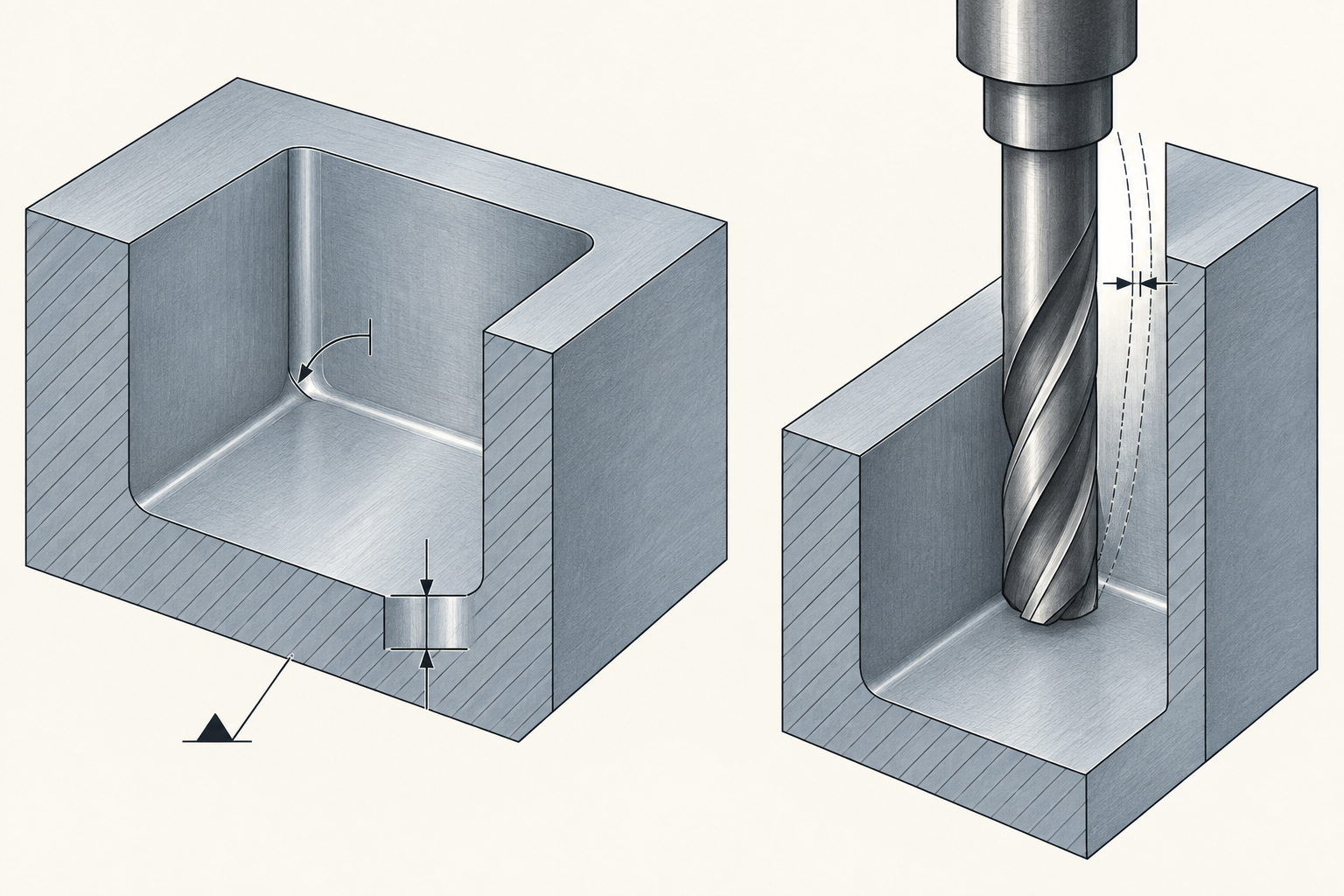
Deep cavities, cross holes, internal corner cleanup, thin walls, and internal threads all share the common problem of tool and tool holder interference. When the length-to-diameter ratio of an end mill exceeds 4–5 times, rigidity drops rapidly; common industry practice is to shorten the overhang, step down in stages, or switch to EDM. Burrs inside cross holes often require secondary deburring, otherwise chips fall off during assembly. Trigger condition: when the feature's depth-to-width ratio makes standard tools unable to reach, or the corner cleanup radius is smaller than the available tool radius, you need to choose among 5-axis, EDM, and cast blanks, rather than continuing to hard-mill with 3-axis.
3. Dimensional accuracy and surface finish are cost steps
The cost between ordinary tolerances (such as ±0.1 mm) and precision tolerances does not grow linearly but rises in steps: the latter often requires more stable machines, stricter clamping, more frequent measurement, and even a temperature-controlled environment. In the industry, precision machining tolerances commonly reach the 0.01 mm level, but this depends on material, size, clamping method, and inspection means, and must be confirmed item by item with the supplier according to the drawing—it cannot be treated as a universal promise. The same applies to surface roughness: tightening Ra from 3.2 to 0.8 may require adding a fine milling or grinding operation. Trigger condition: when a non-mating surface has been mistakenly marked with a precision tolerance, first ask what function it actually affects, and relax it if possible.
4. Batch size and cost: unit cost curves have different shapes
CNC machining has no mold cost and is flexible for one-offs and small batches, but unit cost decreases only limitedly with batch size because every piece occupies machine time. Processes such as injection molding, die casting, and vacuum casting involve one-time mold or silicone mold investment; unit cost is high when the quantity is too small, and only becomes worthwhile past the economic batch point. A common industry judgment is: within a few dozen pieces and still changing in structure, lean toward CNC or 3D printing; above a few hundred pieces, with a stable shape and a need for consistency, mold-based processes begin to gain the advantage. Trigger condition: when the per-piece labor cost already exceeds the amortized mold cost, it's time to recalculate the total.
5. Lead time and equipment: setup time is often overlooked
Delivery time is not just machining time; it also includes programming, tool preparation, making fixtures, and first-article confirmation. Using off-the-shelf standard tools, standard fixtures, and existing program templates can compress setup time; non-standard tools and dedicated tooling require extra scheduling. Trigger condition: when a part's structure requires a dedicated fixture but the batch is very small, it's usually better to change the structure so it returns to standard clamping than to make a set of tooling for just a few pieces. When selecting a process, listing these five items in a comparison table and scoring them one by one is more reliable than choosing by feel.
How does design for manufacturing (DFM) reduce the machining cost of mechanical parts
Process selection often happens after the drawing is already finished, or even after quoting has begun. What DFM (Design for Manufacturing) does is exactly the opposite: it puts machining knowledge back in before the drawing is finalized. For machining mechanical parts, it is not an extra review process, but a lever that can eliminate an entire operation by changing a few dimensions and swapping a few callouts.
Simplify geometry: if it can be turned, don't make it a milled pocket
For parts of revolution, turning forms the shape in a single pass around the circumference, far faster than milling layer by layer around a square profile, and dimensions are easier to hold. In design, changing a "square outer profile + round hole" to a "round outer profile + coaxial hole" turns multiple setups and alignments into a single setup, making geometric tolerances (coaxiality, circular runout) naturally easier to meet.
Counterexamples are also common: an internal cavity that doesn't need corner cleanup is drawn with a 90° sharp corner. Cutting tools are round, so cleaning out to a sharp corner can only be done by EDM or a special small-diameter tool running slowly, which jumps the cost up a tier. Enlarging the internal fillet to match a common tool radius lets milling finish it in one pass.
Reduce non-standard tooling: unify fillets and hole diameters
Five or six different internal fillet radii on one drawing means changing five or six tools, or going off to order non-standard cutters. Unifying to a few standard values (such as R3, R5) reduces both tool changes and non-standard tooling costs. The same applies to threads and hole diameters: taps and drills for common specifications like M6 and M8 are available anywhere, while non-standard threads require dedicated tooling and separate scheduling.
Here's an easily overlooked detail: don't design a hole diameter to exactly match a standard drill bit's diameter—leave a little reaming allowance, otherwise both dimensional tolerance and surface roughness are hard to guarantee.
Loosen non-critical tolerances: tighten only mating surfaces
Marking ±0.01 across an entire drawing is the most common cost multiplier. What truly needs tight control is usually only mating surfaces, locating datums, and sealing surfaces; other dimensions can be marked with general tolerances, so machining doesn't require repeated measuring and repeated tool adjustment. In the industry, precision machining tolerances are often held to the 0.01 mm level, but this comes at the cost of inspection and fixturing—whether it can actually be achieved depends on material, size, and structure, and must be confirmed between the drawing and the supplier, not generalized.
Give tools room to enter and retract, and specify datums and clamping surfaces
For features like deep cavities, cross holes, and internal wall steps, if the tool can't reach in, the only options are changing the process or changing the design. Tool accessibility must be judged at the drawing stage: when the ratio of cavity depth to tool diameter is too large, the tool lacks rigidity and tends to deflect, leaving chatter marks on the surface.
Clamping surfaces are also often overlooked. If the drawing has no flat, clampable process boss or datum surface, the machinist has to figure something out, resulting in extra operations or repeated alignment. Making the design datum and process datum coincide as much as possible reduces the number of transitions from blank to finished part.
The benefit of DFM isn't the abstract "cost reduction" but a very concrete time difference: changing a drawing might be an hour's work, while changing a process is often a full day—re-sequencing routes, re-programming, re-making fixtures. But to be honest: DFM can't save a part whose function is poorly defined. If it's not even settled which surfaces are mating surfaces and which carry loads, solve the function first, then talk about manufacturability.
A few engineering habits for making machined parts reliably
Unified datums: make design, process, and inspection datums coincide as much as possible
Thin walls and slender parts: symmetric material removal, split operations, stabilize shape first if necessary
Order of heat treatment and finishing: change properties first, then hold precision
Surface treatment changes dimensions: allow for plating and anodizing
Gauges and CMM: sampling strategy must match batch size and tolerances
Frequently asked questions about machined part manufacturing (FAQ)
The following questions are the ones readers ask most after reading the previous sections. The answers try to give the basis for judgment rather than a conclusion; for a specific part, you still need to look at the drawing, material, and the supplier's process capability.
For small-batch machined part manufacturing, choose CNC or 3D printing?
Look at two things first: whether the material matches, and whether tolerances are tight. 3D printing (FDM/SLA/SLS/MJF/DMLS) suits parts with complex shapes, very small batches, and mainly for validating structure and assembly; both plastics and some metals can be done, but anisotropy and surface roughness must be accepted up front. CNC machining suits parts needing real material properties and tighter dimensional and geometric tolerances, and is cost-effective from one-offs to small batches—the trade-off is that features like deep cavities and corner cleanup require splitting operations. A compromise is to use 3D printing first to validate shape and assembly, then CNC for functional parts. If both are feasible, sending the drawing out for quotes from both is more reliable than choosing by gut feel.
If the drawing only shows basic dimensions with no tolerances, what does machined part manufacturing follow?
Dimensions without tolerances are usually handled per general untoleranced dimensions; the specific values depend on the standard referenced on the drawing (such as a grade of GB/T 1804 or ISO 2768) and the supplier's default convention—different shops may have different default grades, so confirm once before ordering. More importantly: for functional dimensions like mating surfaces, locating surfaces, and bearing seats, it's best to proactively mark tolerances and datums rather than expecting the shop to guess for you. If there really isn't time to supplement the drawing, at least state in the technical requirements which dimensions are critical and which can be relaxed, to avoid disputes at final acceptance.
Can cast or forged blanks be used directly as finished parts?
In most cases, no. Casting and forging solve forming and material structure problems; dimensional accuracy and surface quality usually don't meet assembly requirements, so machining allowance is generally left, and mating surfaces, hole systems, and datum faces are finished by machining. A few exceptions: non-mating surfaces of sand castings and some external surfaces of die castings can be left unmachined if the drawing explicitly accepts the as-cast condition. The criterion is to look at which surfaces on the drawing have tolerance and roughness requirements—those with requirements must be machined, those without can retain the blank surface. How much blank allowance to leave depends on distortion and fixturing method; leave too little and it can't be machined out, leave too much and you waste material and labor hours.
What tolerances can precision machined part manufacturing generally achieve?
The common precision grade in the industry is around the 0.01 mm level, and the ordinary grade is usually in the 0.05–0.1 mm range, with roughness also varying by process grade. But this is only an order-of-magnitude reference, not a promise from any particular shop: what can actually be achieved depends on the material (aluminum alloy and stainless steel differ greatly), part size and rigidity, fixturing method, tool and machine condition, and whether the measurement method can measure accurately. Thin-walled and slender parts may not be makeable even with very tight tolerances marked, due to distortion. So the right approach is to clearly state critical dimensions, datums, and inspection methods, let the supplier evaluate and then confirm, rather than assuming a certain value can definitely be achieved.
I changed the drawing per DFM suggestions—will it affect part function?
DFM changes manufacturability and should not touch functional definitions, but the prerequisite is that the functional boundaries are clearly stated before making changes. Common changes—enlarging an undersized internal fillet, unifying thread specifications, loosening tolerances on non-mating surfaces, leaving tool entry/exit clearance—generally do not affect assembly or load-bearing behavior. What truly requires caution are changes involving wall thickness, load-bearing cross-sections, sealing surfaces, and fit clearances; these must be confirmed back with the design side. A sound process is: the supplier raises DFM comments, the designer marks each one as "can change / cannot change / needs evaluation," and then the version is finalized. If a suggestion would compromise function, it is better to change the process or add cost than to sacrifice performance for easier machining.
What is the difference and connection between machining and manufacturing: boundaries, inclusion relationships, and order of judgment
| Comparison dimension | Machining | Manufacturing (as a whole) |
|---|---|---|
| Scope | Controlled material-removal cutting operations | All activities from blank to finished product |
| Typical operations | Turning, milling, drilling, grinding, planing, slotting, EDM, wire cutting | The above operations + casting, forging, welding, assembly, heat treatment, surface treatment, inspection |
| Main inputs | Bar stock, plate stock, castings, or forgings (blanks) | Raw materials, purchased parts, standard parts, energy, and tooling |
| Main outputs | Parts meeting dimensional and geometric requirements | Deliverable, assemblable, acceptable products |
| Key cost drivers | Number of setups, tooling, tolerance grade, batch size | Blank method, process route length, heat treatment and surface treatment, inspection plan |
| Common misconceptions | Thinking "machining" equals "done" | Thinking a "manufacturing" quote already includes all cutting operations |
FAQ about machined part production
Are machining and manufacturing the same thing?
No. Manufacturing is the larger set, including blank forming, machining, welding and assembly, heat treatment, surface treatment, inspection, and logistics; machining is only the part of the operations that involves "controlled material removal." A part can undergo only machining, or it can go through the full manufacturing chain.
When should a casting or forging blank be chosen instead of cutting directly from bar stock?
It depends on shape complexity and batch size. Complex internal cavities, large volumes, and thin-walled parts are more material-efficient when cast; load-bearing parts and parts requiring continuous fiber flow lines are better forged; for simple shapes, small batches, and tight lead times, cutting directly from bar or plate stock is often more cost-effective because it eliminates mold costs and blank lead time.
The drawing specifies dimensions after quenching—why still leave grinding allowance?
After quenching, the material hardness is high, and conventional tools cannot cut it; grinding is needed to achieve final precision. If the drawing directly specifies post-quenching dimensions without leaving allowance, the process route must be rearranged. The correct approach is to first rough-turn or rough-mill while leaving grinding allowance, then grind to final dimensions after heat treatment.
What tolerances can machining generally achieve?
In the industry, precision machining tolerances commonly reach the 0.01 mm level, and grinding is one of the main methods capable of reaching this range. But what can actually be achieved depends on the material, feature accessibility, fixturing method, and inspection means—not just the equipment. The tighter the drawing tolerance, the faster cost and inspection requirements rise.
How can confusion between machining and manufacturing scopes be avoided during quoting?
State in the RFQ who supplies the blank, which operations are included, who is responsible for heat treatment and surface treatment, and which dimensions are fully inspected. Clarifying these items is far cheaper than arguing afterward.
Key takeaways
- Machined part manufacturing methods can be roughly divided by "forming method": casting, forging, machining, welding, and heat treatment. Each solves a different problem; they are not mutually substitutable.
- Machining is further divided internally by motion type: workpiece rotates (turning), tool rotates (milling, drilling), both rotate (grinding), neither rotates (planing, slotting), corresponding to different geometric features.
- Selection must pass at least five gates: material, shape and feature accessibility, dimensional accuracy and surface requirements, batch size and cost, lead time and equipment. Missing any one easily leads to rework.
- Manufacturing is the larger set that includes machining: blank forming, welding and assembly, heat treatment, surface treatment, and inspection all count as manufacturing. Confirming the scope before quoting can save a great deal of rework.
- DFM takes effect at the drawing stage: simplifying geometry, reducing non-standard tooling, and unifying fillets and tolerance grades are often more effective than pressing for price cuts later.



