
Why can't metal 3D printed parts be used directly after "coming out of the build chamber"?
The four "native problems" of as-built parts
- Residual stress: the printing process involves local rapid melting and solidification followed by cooling, and the inside of the part feels as if it has been repeatedly pulled, locking stress inside.
- Unmelted powder: powder in the powder bed and storage tank, and powder accumulated in internal cavities and channels, cannot be considered usable until it is cleaned out.
- Rough surface: "layer lines" remain between layers, and Ra is usually significantly higher than on machined surfaces, affecting both mating surfaces and appearance.
- Potential porosity: shrinkage porosity, lack of fusion, and microcracks may hide inside; they cannot be seen from the outside, yet they directly relate to fatigue and load-bearing capacity.
From "print complete" to "usable," post-processing is a chain

Step one: powder cleaning and recovery—an overlooked but hugely influential upstream step
Many people's imagination of metal 3D printing stops at the moment "the machine stops and the part is taken out." In reality, especially for powder bed fusion processes, the part is still buried in a full bed of powder when it comes out. What this step requires is not just "digging the part out," but handling the entire powder system—it relates simultaneously to part quality, operational safety, and the consistency of the next print batch. In the entire chain of metal 3D printing post-processing, powder cleaning is the earliest and most easily underestimated link.
The objects to be cleaned are not only the part surface, but also the powder bed and storage tanks
After printing ends, most of the unmelted powder remains in the powder bed, while another portion is in the powder supply and recovery storage tanks. These powders are usually recyclable and reusable, but only on the premise that the recovery process itself is clean. Typical cleaning objects include:
- Unmelted powder on the part body: attached to the surface, steps, and beneath overhangs, directly surrounding the support roots.
- Accumulated powder in internal cavities and channels: in structures such as conformal cooling channels, lightweight lattices, and deep holes, powder often gets stuck inside and cannot be seen with the naked eye.
- Powder bed and storage tanks: need to be emptied and sieved, then the reuse ratio decided.
If the part is not cleaned thoroughly, at best residual powder sinters onto the surface during subsequent heat treatment; at worst, powder blockage in internal cavities causes flow performance to fail to meet standards. If storage tank management is inadequate, it directly affects the powder spreading and melt pool stability of the next batch.
Common cleaning methods and their respective boundaries
There is no "one method that handles everything" for cleaning; they are usually combined according to part structure:
- Suction and negative pressure cleaning: the most basic method, suitable for open surfaces and shallow cavities; limited effect on deep cavities and fine channels.
- Vibration / tapping assistance: helps loose powder fall off, but has limited effect on powder that has already slightly bonded.
- Ultrasonic cleaning: suitable for parts that can withstand liquid immersion, with advantages for complex internal cavities; but it is a "wet process" for the powder itself, and subsequent drying is required.
- Media blasting / shot peening: can both clean powder and incidentally improve the surface, commonly used on external surfaces; reachability into internal cavities depends on whether the nozzle can be inserted.
A pragmatic judgment is: first see whether the most hidden feature of the part can be cleaned, then decide which method to use. If the internal cavity cannot be cleaned at all, in many cases the problem must go back to the design stage—leave powder removal holes, or reserve subsequent machining to open them through.
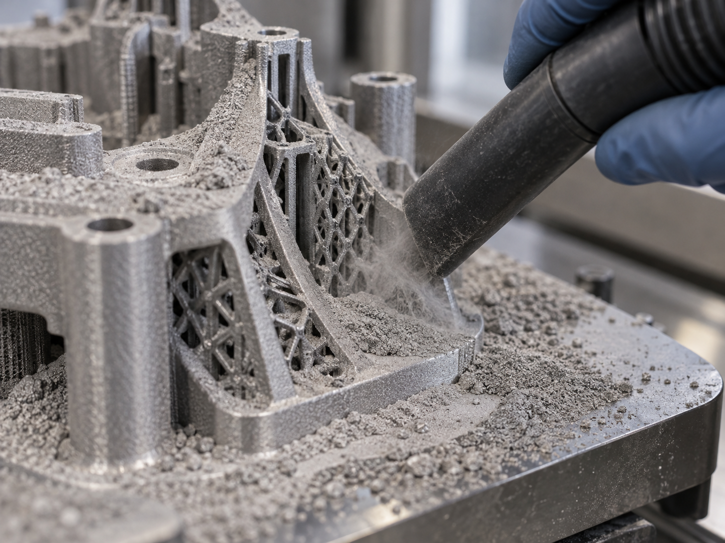
Why sieving and blending ratio of recovered powder affect the next batch
Recovered powder is not as simple as "pour it back in and keep using it." After multiple cycles, the particle size distribution, oxygen content, flowability, and sphericity of the powder all change. The industry's usual practice is to sieve the recovered powder, remove excessively fine powder and agglomerates, and then blend it with new powder in a certain proportion. Parameters such as blending ratio, mesh size, and number of cycles are often jointly determined by material specifications and equipment manufacturer recommendations, and are not fixed values.
This is also why powder management is often discussed separately: it determines whether the 10th part and the 1st part are the same part. For small-batch prototyping, the impact may not be obvious; once entering batch production or scenarios sensitive to performance consistency, powder state is a variable that must be recorded and controlled. This is also where the value of some automated powder handling systems lies—reducing manual intervention, reducing contamination, and maintaining powder integrity.
If this link is not done well, all subsequent heat treatment and surface treatment are built on the basis of "unknown incoming material state," and problems are very difficult to troubleshoot. Only after cleaning is completed does the part truly enter the next process: support removal and stress relief. If you have a specific part and want to discuss the cleaning and post-processing route, you can send the structure along through the quote entry for evaluation.
Support removal and stress relief: first "loosen" the part before heat treatment
The previous section finished cleaning the powder, and the part surface is clean, but internally it is still tightly wound up—that is the residual stress left by the printing process. The heat source in metal 3D printing repeatedly scans the same layer and the same area; the melt pool cools and contracts rapidly, while the adjacent old track pulls it back, and each layer winds up the next layer like a spring. This is especially obvious in laser powder bed fusion (LPBF) parts: the thicker the part and the closer to the substrate, the more concentrated the stress. If this force is not released, the part may deform on its own later when supports are cut, when it is put on a lathe, or even after being left for a few days.
So it is necessary to distinguish two things that are often conflated: support removal (mechanical removal, wire cutting to sever, machining away connection points) and stress relief annealing (heating the part to below the material's recrystallization temperature and holding it, allowing stress to release slowly). The former is physically dismantling connections; the latter is the introductory lesson of heat treatment. The order usually cannot be reversed.
Why removing supports first can cause problems
The supports themselves are constraints. With the supports still attached, the part is effectively held and pulled, and the stress is "locked" into the structure. Once the supports are released with flush cutters or wire cutting, the constraints disappear, the stress redistributes, and the part may warp to one side. Thin-walled parts, long cantilevers, and large flat surfaces are the most likely to show a "spring" at the moment of cutting—dimensions can shift by a few tenths of a millimeter, which may not be visible to the naked eye, but the assembly surface is already off.
The same applies to going straight to CNC finishing. Clamping force adds to residual stress, and as each layer is cut, the stress balance is disrupted, so the part moves and the dimensional chain drifts further and further. The effect is relatively small on rigid, thick parts, but on slender, thin-walled, or hollowed-out structures it is almost inevitable.
How to sequence it: decide by rigidity and subsequent operations
- Rigid, thick parts: remove supports → stress-relief annealing → finishing. The order is relatively flexible, and annealing is mainly for dimensional stability.
- Thin-walled / slender / large flat parts: first stress-relief annealing (with supports or partial supports still attached), then remove supports, and finally finish machine. Let the stress release while the part is still supported.
- Parts cut off by wire cutting: the cut itself is a stress release, so after cutting it is best to add another stress-relief step, especially for datum surfaces that will later be precision ground.
- Parts that will later undergo HIP or solution aging: stress relief can be merged into the heat treatment process, but the schedule must be confirmed with the process provider, so as not to repeat annealing and coarsen the grains.
Here is a clue for judgment: if the critical dimensional tolerance on the drawing is within ±0.05 mm, or if the part has explicit flatness or parallelism requirements, then put stress-relief annealing into the process—don't gamble that it won't deform. As for temperature, holding time, and heating rate, these depend on the material grade (titanium alloys, stainless steel, aluminum alloys, and nickel-based alloys differ greatly) and section thickness, and are parameters that must be confirmed according to material standards and drawings; they cannot be applied by rule of thumb.
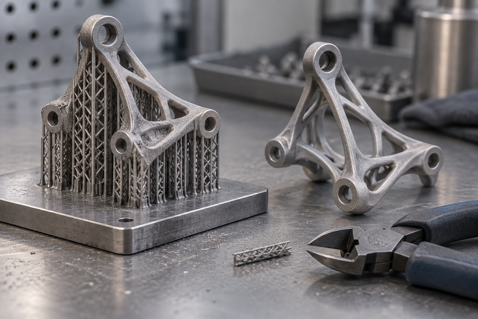
To sum it up in one sentence: removing supports is "releasing physical constraints," while stress relief is "releasing internal constraints." In metal 3D printing post-processing, which of these two steps comes first often affects the final dimensions more than which heat treatment is chosen afterward. Get the order right, and the subsequent heat treatment and finishing can be discussed on a stable basis.
Heat treatment: the "basic course" for eliminating internal stress and tuning properties
Stress-relief annealing is about "letting the part go," while formal heat treatment is about "making the part perform well." The melting—solidification process in metal 3D printing is very fast, grains grow unevenly, and the microstructure deviates from equilibrium. Putting the same batch of parts in a furnace for one correct heat treatment often determines the performance ceiling more than repeatedly fine-tuning the printing parameters. So when discussing metal 3D printing post-processing, the heat treatment step cannot be avoided.
What annealing, solution + aging, and quenching + tempering each do
Annealing is the mildest option: heat to a certain temperature, hold, then cool slowly. Its main purposes are to eliminate residual stress, soften the microstructure, and stabilize dimensions. It does not pursue high strength, but rather keeps the part from deforming unpredictably during subsequent machining or use.
Solution + aging is the specialty of aluminum alloys, nickel-based alloys, and some titanium alloys. First dissolve the strengthening phases back into the matrix (solution treatment), then at a lower temperature let them precipitate as fine particles (aging), and the strength and hardness increase. Because metal printed parts solidify quickly, they often have non-equilibrium microstructures to begin with, and solution treatment can also bring the microstructure back to a uniform state.
Quenching + tempering is mainly used for steel and some titanium alloys. Quenching "freezes" the high-temperature microstructure into martensite, which is hard but brittle; tempering then adjusts it back to a balance of toughness and strength. Aerospace structural parts often involve quenching + tempering as a type of hardening and tempering route, while molds and hot-work parts place more emphasis on hardness and red hardness after tempering—that is, whether hardness can still be maintained at high temperature.
What heat treatment can change and what it cannot
What it can change are internal stress, grain size, phase composition, and the resulting strength, hardness, ductility, and fatigue performance. Grain refinement is especially valuable: for the same material, finer grains usually mean better strength and toughness. Dimensional stability is also a real benefit—the part is less likely to "drift" during subsequent machining and use.
What cannot be eliminated are the internal pores and shrinkage porosity that already exist. Heat treatment cannot "weld" the holes shut—that has to be left to hot isostatic pressing. In addition, heat treatment brings deformation and oxidation; the higher the furnace temperature and the faster the cooling rate, the more likely the part is to warp or shift in dimensions. So the sequence of heat treatment and finish machining must be thought through in advance: usually heat treat first, then machine the critical surfaces, to avoid cutting away the dimensions you worked so hard to heat treat.
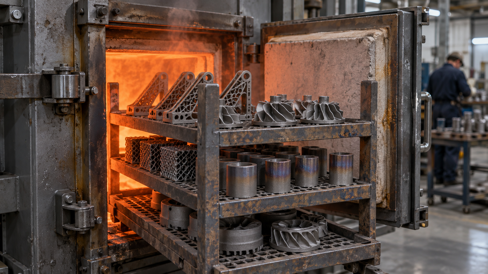
Basis for selection: material grade, cross-sectional size, where it is used
Choosing a heat treatment regimen starts with the material grade, not the part shape. In the same furnace, the process windows for titanium alloy and aluminum alloy are very far apart; for the same grade, thin-walled parts and thick solid parts cannot simply follow the same curve. Cross-sectional size determines holding time and cooling rate; if a thick part cannot be cooled through, the performance at its core is not the same thing as at its surface.
Next, look at the application. For appearance parts and non-load-bearing parts, stress relief annealing is often enough; only load-bearing parts and parts sensitive to fatigue life require complete heat treatments such as solution treatment + aging or quenching and tempering; for molds and hot-work parts, hardness and red hardness must come first. A common industry practice is that the heat treatment regimen is jointly confirmed by the material standard, the drawing requirements, and the heat treatment supplier, and the specific temperature, holding time, cooling rate, and furnace cooling/air cooling method must all be written into the process document, rather than just picking a number based on experience. When you get the drawing, first confirm two things: the heat treatment regimen recommended in the material standard, and which surfaces on the part will be finish machined later—this determines how much allowance to leave before heat treatment.
Hot isostatic pressing: when is it really needed?
What exactly does it change
Not a universal repair, and not a mandatory option

Surface treatment: from removing layer lines to improving corrosion and wear resistance
When a metal 3D printed part is taken out of the machine, its surface condition is often far from the word "finished product." Layer lines left by laser melting, unmelted powder particles, fracture burrs after support removal, and subtle warping caused by thermal stress—these are all on the part's skin. The surface treatment step in metal 3D printing post-processing must solve the transition from this rough surface to a usable surface.
But surface treatment has an easily overlooked premise: what problem it solves depends on what the part is used for. Two parts printed by the same machine, one for appearance display and one installed on a hydraulic valve body in a corrosive environment, may have completely different surface treatment plans.

Removing layer lines and improving appearance: sanding, polishing, bead blasting, electropolishing
Removing layer lines is the most intuitive category of surface treatment. The depth of layer lines on metal printed parts depends on layer thickness and printing parameters, and usually requires progressive sanding from coarse to fine. A common industry practice is to start with sandpaper of several hundred grit and gradually progress to several thousand grit; after high-grit sanding, the surface becomes brighter and approaches a mirror-like effect. The key word here is "progressive"—if you skip intermediate grits and go directly to high grit, the scratches from the previous step are instead pressed into the surface and are very difficult to remove afterward.
Sanding is usually followed by polishing. Manual polishing is suitable for simple external surfaces that can be reached; complex internal cavities and deep crevices are difficult to reach with sandpaper, so media blasting, abrasive flow, or electropolishing are more practical in those cases. Media blasting can also clean residual powder at support roots and particles attached to the surface, achieving two goals at once.
Blasting itself is also graded: coarse media removes layer lines quickly but leaves a darker surface, while fine media gives a more uniform surface but is less efficient. The choice depends on the part's appearance requirements and whether subsequent coating is needed—before coating, it is usually not necessary to polish to a mirror finish; instead, a certain roughness is needed to ensure adhesion.
Functional surface treatments: anodizing, electroplating, passivation, nitriding
If a part must withstand corrosion, wear, or repeated friction, the goal of surface treatment shifts from "looking good" to "being durable." Aluminum alloy parts are often anodized to form a dense oxide film on the surface, improving corrosion resistance and hardness; electroplating can deposit coatings such as nickel and chromium on the surface of metal parts, combining corrosion resistance and decoration; stainless steel parts commonly undergo passivation, using chemical methods to remove free iron from the surface and restore the integrity of the passive film.
Nitriding belongs to another category—it is not just a surface covering, but diffuses nitrogen into the surface layer to form a hardened layer. It is suitable for scenarios requiring high surface hardness while maintaining toughness in the core, such as mold inserts or wear-resistant guide rails. This type of process is selective about materials, and not all metal printing materials are suitable.
Surface treatment is not an independent step; it has a sequential relationship with the preceding support removal, heat treatment, and hot isostatic pressing. For example, the surface may change after hot isostatic pressing, requiring reassessment of the surface treatment plan; and if sanding is insufficient before anodizing, the anodizing may instead magnify scratches. Every step of metal 3D printing post-processing prepares conditions for the next step, and surface treatment is usually one of the later steps in the chain.
Finishing and inspection: bringing parts to final dimensions and acceptance standards
After heat treatment and surface treatment are completed, many metal 3D printed parts look like they are "about right," but they are often still a final stretch away from acceptance standards. The reason is simple: additive manufacturing excels at building complex shapes in one go, but it is not good at holding mating dimensions firmly within tolerance bands. Any functional surface that relies on friction, sealing, tightening, or rotation basically needs subsequent machining to back it up. This step is not remedial work, but a key process that determines whether the part can be installed and whether it can run.
Why machining is still needed after post-processing
The typical accuracy of as-printed parts is commonly in the range of ±0.1 mm or wider in the industry (specifics depend on the process, material, and structure, and must be confirmed according to drawings and the supplier). This level is sufficient for installing a housing or making a bracket, but positions such as bearing seats, threaded holes, seal grooves, locating pin holes, and gear meshing surfaces usually require tighter dimensional tolerances and geometric tolerances—coaxiality, perpendicularity, and flatness cannot be adjusted merely through printing parameters and must be ensured by CNC turning and milling. Therefore, a common practice is to intentionally leave machining allowance on the order of 0.3–0.5 mm on critical surfaces during printing, and then finish them on a machine tool. Too little allowance means it cannot be cut; too much wastes time and material. This allowance value should be clearly marked on the drawing or determined together with the machining provider.
To determine which features must have allowance, you can follow three clues: first, mating relationships—any surface that must fit, insert, or interference-fit with another part; second, motion functions—the working surfaces of bearings, guide rails, and gears; third, sealing and fastening—O-ring grooves, threads, and flange sealing surfaces. Conversely, purely cosmetic surfaces, non-mating reinforcing ribs, and internal flow channels generally do not need allowance; leaving allowance instead adds the trouble of removing it. This step of metal 3D printing post-processing is essentially upgrading "correct shape" to "correct dimensions."
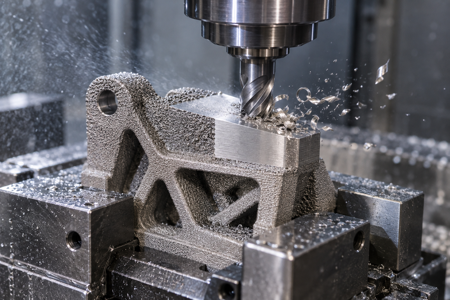
The special nature of inspection for additive parts: visible outside, invisible inside
In the inspection stage, additive parts differ from traditional forgings and castings. Internal defects in traditional blanks are controlled by the forging or casting process itself, whereas metal printing melts and solidifies layer by layer, so internal defects such as lack of fusion, porosity, and shrinkage porosity may occur, and their locations are often hidden inside the part. Therefore, in addition to conventional dimensional inspection—calipers, micrometers, coordinate measuring machines (CMM)—load-bearing parts and fatigue-life-sensitive parts often also require non-destructive testing: industrial CT can show internal pore distribution, while ultrasonic, penetrant, and radiographic testing each have their applicable scenarios. Whether to perform it and to what level depends on the part's service conditions and acceptance standards; not all parts need CT.
3D scanning has its own unique use here. Printed parts tend to warp at thin walls and sag at long overhangs, and these deformations cannot be measured with calipers, but 3D scanning can overlay the actual point cloud with the CAD model and use a color deviation map to intuitively show where there is deviation and by how much. During first article approval, batch sampling, and reverse comparison, this kind of "visualization of overall deviation" is more efficient than point-by-point measurement. It does not replace precise CMM measurement, but it can quickly tell you whether the part is deviating overall in the right way.
To sum up this step in one sentence: only when metal 3D printing post-processing reaches finishing and inspection does the "printed shape" truly become an "acceptable part." The earlier steps govern performance, appearance, and internal quality; this step governs the last millimeter of difference between the part and the drawing. That last millimeter often determines whether the part works as soon as it is installed, or causes problems the moment it is installed.
How to choose: work backward from the part's application to the post-processing combination
When metal 3D printing post-processing reaches the selection stage, the most common mistake is "ranking by process popularity"—hearing that hot isostatic pressing is good and wanting to run everything through it, hearing that electropolishing looks beautiful and arranging it for everything. The truly workable approach is the reverse: first answer where the part will be used, then work backward to determine which processes are needed. Once four questions are answered clearly, the combination is basically settled: operating environment, load type, appearance and assembly precision, cost and lead time.
Four dimensions, clarified one by one
- Operating environment: Will it contact corrosive media, endure prolonged high temperatures, or reciprocating wear? If there is corrosion, prioritize passivation, anodizing, or coating; if there is high temperature, the heat treatment regimen must be established first; if there are wear surfaces, consider nitriding or localized hardening.
- Load type: Static load, fatigue, and impact have completely different requirements for internal quality. Only load-bearing parts sensitive to fatigue life are worth putting hot isostatic pressing on the agenda; for general static-load structural parts, doing stress-relief annealing and dimensional stability solidly is often more practical.
- Appearance and assembly precision: Exposed decorative surfaces may require grinding and polishing or even mirror finishing; mating surfaces, threads, bearing seats, and sealing surfaces must be left with machining allowance and ensured by subsequent CNC.
- Cost and lead time: Every added process incurs time and expense. A common situation in the industry is that post-processing accounts for a considerable proportion of total cost—the exact amount depends on part complexity and precision requirements. Before quoting, first ask, "Does this process solve a real problem?"
Three typical routes for three types of parts
Applying the above dimensions to specific parts will roughly converge into three routes. They are not standard answers, but starting points for judgment.
- Appearance display parts / non-load-bearing parts: support removal → stress-relief annealing (recommended for thin-walled or large flat parts) → grinding and polishing or sandblasting → optional anodizing or electroplating for coloring. The focus is surface consistency and absence of layer lines; internal quality can be controlled conventionally.
- Load-bearing structural parts / fatigue-sensitive parts: stress-relief annealing → hot isostatic pressing (when internal quality requirements are high) → solution treatment + aging or quenching + tempering → CNC finishing of critical surfaces → nondestructive testing. This route has many steps and a long cycle, but what it buys is reliability of internal density and mechanical properties.
- Flow-channel parts / complex internal-cavity parts: powder cleanup and residual powder treatment in internal cavities must be done thoroughly → stress-relief annealing → internal cavity surface treatment (media blasting, electropolishing, or chemical polishing depending on material and channel size) → finishing of interface surfaces and flow testing. Manual polishing of internal cavities is very difficult; alternative methods must be confirmed for feasibility with the processor in advance.
Note that among these three routes, almost none is finished with "just one process." Metal 3D printing post-processing is essentially a combination: heat treatment governs internal performance, surface treatment governs appearance and corrosion/wear resistance, and finishing governs final dimensions. Each handles one segment, and missing any segment can leave you stuck at the acceptance stage.

If you have a specific part, material, and acceptance requirements on hand, clearly state the application and critical dimensions, then go to the quote entry or the CNC machining capabilities page to confirm how subsequent finishing and inspection will be connected. That makes it easier to get it right the first time than simply comparing prices. The boundaries of post-processing selection ultimately come back to the tolerances, roughness, and operating conditions on the drawing.
Frequently asked questions
The following questions are basically the ones readers ask most often after reading the preceding process chains. The answers try to provide the basis for judgment rather than absolute promises.
After a metal 3D printed part comes out of the machine, can it be used directly after just grinding and polishing?
In most cases, it is not enough. Grinding and polishing only change the surface and cannot solve internal stress, internal porosity, or dimensional issues on critical mating surfaces. If the part is only for appearance display, does not bear load, and is not assembled, support removal plus surface treatment may be sufficient; but as long as it involves fitting, sealing, fatigue, or load bearing, stress relief, heat treatment, and even hot isostatic pressing and finish machining usually need to be scheduled in. The starting point for judgment is where the part is used, not choosing the process first.
For support removal and stress relief annealing, which should be done first?
Usually stress relief is done first, then supports are cut, especially for parts with poor rigidity, thin walls, and large spans. The thermal cycles during printing leave residual stress in the part. If the supports are cut first, the part loses restraint, and when the stress is released it is prone to warping or even cracking. For thick, solid parts with very good rigidity, the order can be more flexible, but the specific arrangement should be confirmed with the processor according to the part structure; do not assume a one-size-fits-all approach.
Should hot isostatic pressing be done once for all metal 3D printed parts?
No. Hot isostatic pressing is mainly aimed at scenarios with extremely high internal quality requirements, such as load-bearing parts, fatigue-life-sensitive parts, and critical medical parts. It can close internal porosity, shrinkage porosity, and microcracks. A common industry statement is that density can approach 100%, but the specific effect depends on the material and process. It also affects dimensions and surfaces, so allowance usually needs to be left and subsequent finish machining coordinated. For parts with ordinary internal quality requirements, doing it may be a waste of cost.
To what extent should surface treatment be done, and how do you judge whether it is enough?
It depends on the application. If only appearance is required, grinding to several hundred grit and then polishing is usually acceptable; if corrosion and wear resistance are required, functional treatments such as anodizing, electroplating, passivation, and nitriding should be considered; if there are sealing or fitting requirements, surface roughness often needs to be written into the drawing and then inspected. During grinding, sandpaper grit is gradually increased from several hundred grit to several thousand grit. Higher grit surfaces are brighter, but manual grinding of complex internal cavities and deep crevices is difficult; in this case, media blasting or polishing is more practical. The final basis is the drawing annotations and inspection results.
After post-processing, why is CNC finish machining still needed?
Because the dimensional and geometric accuracy of additive forming usually cannot meet the requirements of features such as mating surfaces, threads, bearing seats, and sealing surfaces. These locations generally need machining allowance left, and after post-processing is completed, CNC turning and milling are used to ensure tolerances. In addition, internal defects in additive parts require non-destructive testing, and geometric deviations can be compared with the aid of 3D scanning. Which features must have allowance left is best aligned with the processor at the drawing stage, to avoid discovering after post-processing is done that there is no material left to cut.
Key takeaways
- After a metal 3D printed part comes out of the build chamber, it usually cannot be used directly: internal stress, porosity, rough surfaces, adhered powder, and dimensional deviations may all be present.
- Post-processing is a chain, not a single process: powder removal and recovery → support removal/stress relief → heat treatment or hot isostatic pressing → surface treatment → finish machining and inspection.
- Three types of processes solve three types of problems: heat treatment adjusts properties and relieves internal stress, hot isostatic pressing compresses internal defects and improves density, and surface treatment changes appearance, corrosion resistance, and wear resistance.
- Selection should work backward from the part's final application: the service environment, load type, appearance requirements, assembly precision, and cost and lead time jointly determine the combination.
- Powder handling is the most easily overlooked, yet it simultaneously affects print quality, operational safety, and the stability of mass production.



