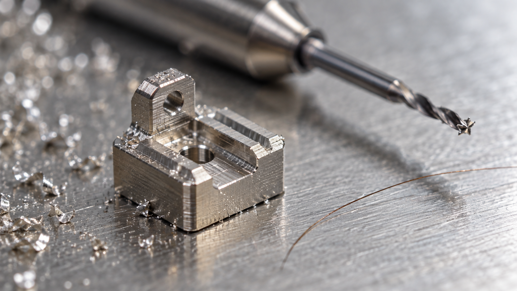
Where Exactly Is Micro Part Machining "Small": Why Large-Part Processes Cannot Be Scaled Down Proportionally
Precision Micro Part Machining Process Division Table: What Features Micro Milling, Micro Turning/Swiss Turning, Micro EDM, Wire Cutting, and Laser Each Handle
The counterintuitive point is here: what determines the micro part machining route is not the machine brand, nor "how many axes," but four things—feature type, material, tolerance band, and batch size. On the same drawing, the housing goes to micro milling, the shaft pin goes to micro turning, the sharp-cornered internal slot in hard material goes to EDM, and the thin foil goes to laser. Dividing processes by feature rather than by equipment name is what keeps quotes and yield stable.
See it in one table: features determine the process, not the machine tool
| Feature / Location | Common Process | Typical Parts | Volume Notes |
|---|---|---|---|
| Outer contour, shallow cavity, bracket | Micro milling (small-diameter end mill) | Housing, connector base, micro bracket | Small tool diameter requires lower feed and depth of cut; thin walls easily deflect |
| Shaft, bushing, pin, cylindrical surface | Micro turning / Swiss turning | Micro shaft, pin, sleeve | Swiss turning suits slender parts; volume relies on bar feeder repeat positioning |
| Holes, threads, locating pin holes | Drilling, boring, tapping, reaming | Locating holes, micro threaded parts | Mark critical and non-critical holes separately; inspection intensity differs |
| Hard materials, sharp internal corners, deep narrow slots | Micro EDM / sinker EDM | Micro gears, hard mold inserts | Electrode wear must be compensated; volume depends on electrode consistency |
| Through narrow slits and hard material contours | Micro wire cutting | Die cutting edges, narrow-slit parts | The cutting wire is thin; wire travel and positioning accuracy determine dimensional stability |
| Thin foil, glass, some plastics | Laser micromachining | Thin sheets, micro-hole arrays, brittle parts | The heat-affected zone and edge quality need to be evaluated according to the application |
Use numbers to anchor the scale of "small": in the industry, common micromachining tool diameters can be smaller than about 0.015 inches, down to the level of about 0.001 inches (about one-third of a human hair); precision tolerance bands often fall within ±0.001–0.01 mm, and medium tolerances are about ±0.01–0.05 mm. These are common ranges for judgment, not promised values—whether they can be achieved depends on the feature, material, and batch size, and the final basis is the drawing and factory confirmation. This is especially true for batch micro part machining: being able to make one piece does not mean a thousand pieces will all be the same. Once the process route is determined, the remaining difficulty shifts from "can it be made" to "is every piece consistent."
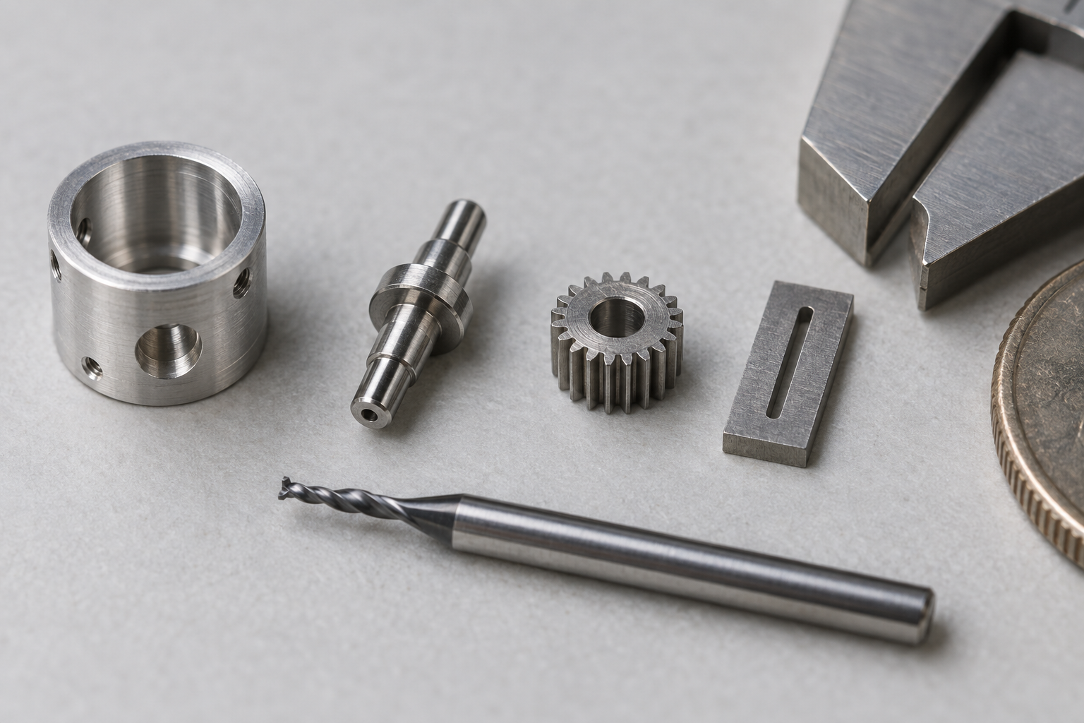
When micro EDM or wire cutting must be used instead of hard milling
Next, let's discuss a type of feature that is most easily misjudged in the table above. The counterintuitive point is: the more a feature "looks like an internal corner that was milled," the more likely it cannot be milled. The failure of hard milling is not insufficient precision, but that the tool simply cannot get in—deep narrow grooves, sharp internal radii, and right-angle cleanout at the bottom of deep cavities. Once the diameter of a micro end mill shrinks below 0.5 mm, rigidity drops sharply, and deflection and chipping cause both dimensions and surface finish to spiral out of control.
Four cases where hard milling fails first
- Hard materials: hardened steel, cemented carbide, ceramics. Micro milling tool wear is far faster than is economical, and changing tools halfway through machining loses the datum.
- Deep narrow grooves and thin walls: with a large length-to-diameter ratio, the tool deflects, thin walls are pushed out of shape by cutting forces, and the more they are clamped, the more they deviate.
- Sharp internal corners: a milling cutter is always a body of revolution, and the internal radius is limited by the tool radius. A drawing marked R0.05 is essentially declaring that it cannot be milled.
- Poor tool accessibility: features hidden inside cavities or at an angle to the spindle may not be reachable even with five axes.
Among these four categories, micro EDM (sinking/plunge type) handles micron-level parts with special shapes, such as small-module gears, special-shaped micro holes, and cemented carbide inserts; micro wire cutting handles through contours and narrow slits. In the industry, common cutting wire diameters can reach about 0.001 inches, and with a high-resolution positioning scale for contour compensation, the tolerance band usually falls in the micron range—the exact achievable value depends on the material, thickness, and machine condition. Mark the critical dimensions clearly on the drawing before discussing it.
The limiting conditions must be stated clearly: using EDM or wire cutting does not mean it is better, nor does it automatically reduce cost. They are slow and require electrode or wire-threading preparation, and are only reasonable when geometry, tolerance, and tool accessibility all prove that hard milling will not work. In batch micro part machining, if the feature can be stably produced by micro milling, hard milling is still more cost-effective than EDM.
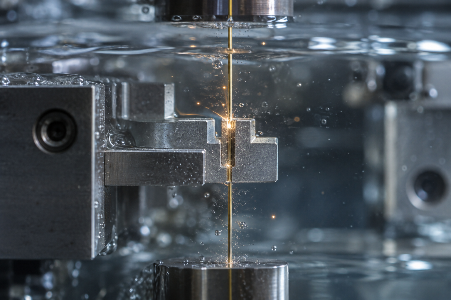
Batch micro part machining: if a single trial piece passes, why does mass production still collapse?
Many people think the risk in batch micro part machining is "whether it can be made." In fact, a single trial piece often passes smoothly—the machinist can manually align it, reduce the feed by feel, and inspect them one by one. What really collapses is repeatability: the hundredth piece is no longer the same part as the first.
Scaling down dimensions amplifies physical effects. Clamping force on millimeter-scale parts can directly cause elastic deformation or even plastic indentation; cutting heat cannot dissipate in time, and spindle thermal elongation and workpiece thermal expansion stack onto micron-level tolerances; a few microns of tool wear is a minor issue on a shaft tens of millimeters long, but on a 2 mm pin it becomes dimensional drift. Deep narrow grooves and thin walls also worsen tool deflection, and machining time lengthens accordingly—once batch production is scheduled at a single-piece pace, both cost and consistency spiral out of control.
Where do the three common collapse points in batch production usually appear?
- Clamping repeat positioning: if the datum surface of soft jaws, dedicated fixtures, or vacuum chucking is unstable, position accuracy scatters after part changeover. In batch micro part machining, the fixture itself must be verified first.
- Accumulated thermal deformation: continuous machining without letting the machine tool and workpiece return to thermal equilibrium causes dimensions to drift in one direction over time, rather than fluctuate randomly.
- Dimensional drift after tool wear: micro tools have short life and a steep wear curve, so tool change or compensation cycles need to be set, rather than running until breakage.
Material and heat treatment sequence will consume both tolerance and cost
Getting the sequence wrong is more expensive than choosing the wrong process. For steel parts that need hardening, you can first turn/mill to near size, then heat treat, and finally finish with micro EDM or grinding—leaving deformation to be handled after heat treatment. Another approach is to directly choose pre-hardened steel, eliminating the subsequent heat treatment step and the associated deformation risk and secondary clamping. Engineering plastics such as POM and PEEK are often used for insulation, wear resistance, or low-friction parts. They have low cutting forces and are easy to machine, but their coefficient of thermal expansion is large, so batch production relies more on control of cooling and measurement rhythm.
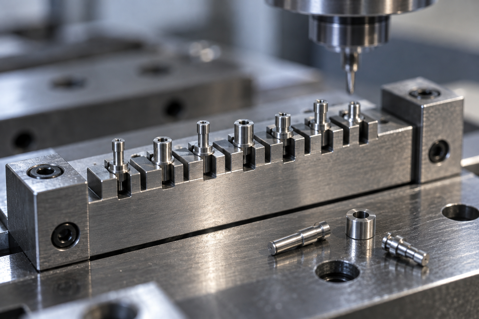
Inspection closed loop and quotation preparation: how to verify micro features and how to provide drawings
A counterintuitive point: in micro part machining, inspection often determines the process earlier than machining does. Machining only reaches where the tool can reach, and inspection only accepts where the probe can reach—probe diameter, probe accessibility, and datum surface size can directly rule out a route that could otherwise have worked.
Therefore, acceptance in precision micro part machining usually does not rely on a single caliper: CMM measures form and position, optical projectors and microscopes inspect micro contours, burrs, and edge chipping, and surface roughness testers measure functional surfaces. Critical holes and non-critical holes should be marked separately on the drawing—the former fully inspected or with tightened criteria, the latter sampled. A common industry practice is to classify by function rather than inspect everything, with specifics confirmed according to the drawing and application.
When requesting a quote, picking out the "critical dimensions" is more useful than reporting the quantity
Frequently Asked Questions
The following are the most frequently asked questions after reading this article, centered on practical judgments regarding micro part machining, precision micro part machining, and batch micro part machining.
Is micro part machining really just scaling down a large part proportionally?
No. When dimensions shrink, clamping force, cutting heat, tool deflection, and vibration are amplified, and the physical rules of material removal change accordingly. Therefore, process selection is not proportional scaling, but rather a re-division of labor based on feature type, material, tolerance, and batch size.
In precision micro part machining, how exactly do you choose between micro milling and micro EDM?
Look at the features first. Open features such as housings, brackets, and shallow grooves are prioritized for micro milling; micro EDM or wire cutting is considered only for hard materials, deep narrow recesses, sharp internal corners, or locations difficult for tools to reach. Multi-axis or special processes do not automatically reduce cost; they are worth using only when geometry, tolerance, and tool accessibility justify them.
Why can a single-piece trial pass, but batch micro part machining tends to fail?
Single-piece trials rely on flexibility, while batch production relies on repeatability. Batch failure points are usually not in “being unable to make it,” but in repeated positioning during clamping, accumulated thermal deformation, and dimensional drift after tool wear. Deep narrow recesses and thin walls further increase deflection and machining time, amplifying these errors.
Do material and heat treatment sequence affect micro part machining?
Yes. Pre-hardened steel can avoid deformation caused by subsequent heat treatment, and engineering plastics such as POM and PEEK are suitable for insulating wear-resistant parts. If the sequence is set incorrectly, tolerance and cost will both spiral out of control. The specific material selection needs to be confirmed based on the drawing and application.
How are micro features inspected, and should critical holes and non-critical holes be separated?
It is recommended to separate them. CMMs, optical projectors, microscopes, and surface roughness testers are used for micro structures and edge precision, and the inspection intensity for critical holes and non-critical holes differs. Only by marking them separately on the drawing can the inspection loop truly correspond to the machining requirements.
Key takeaways
- When choosing a process for micro part machining, look at four things: feature type, material, tolerance band, and batch size—not the machine model or number of axes.
- Micro milling/micro turning handle shaping, micro EDM and wire cutting handle hard materials and sharp internal features, and laser handles thin foil, brittle materials, and plastics; they divide work by feature rather than replace one another.
- Shrinking dimensions amplifies clamping force, cutting heat, tool runout, and vibration; the common scrap cause for micro parts is deformation, not tool breakage.
- The core risk in volume micro part machining shifts from "can it be made" to "is every piece the same," relying on automation, repeatable clamping, and an inspection loop rather than the feel of single-piece trial runs.
- Materials such as pre-hardened steel, POM/PEEK, and the heat treatment sequence directly affect deformation and cost of micro parts; the earlier they are decided, the less trouble later.



