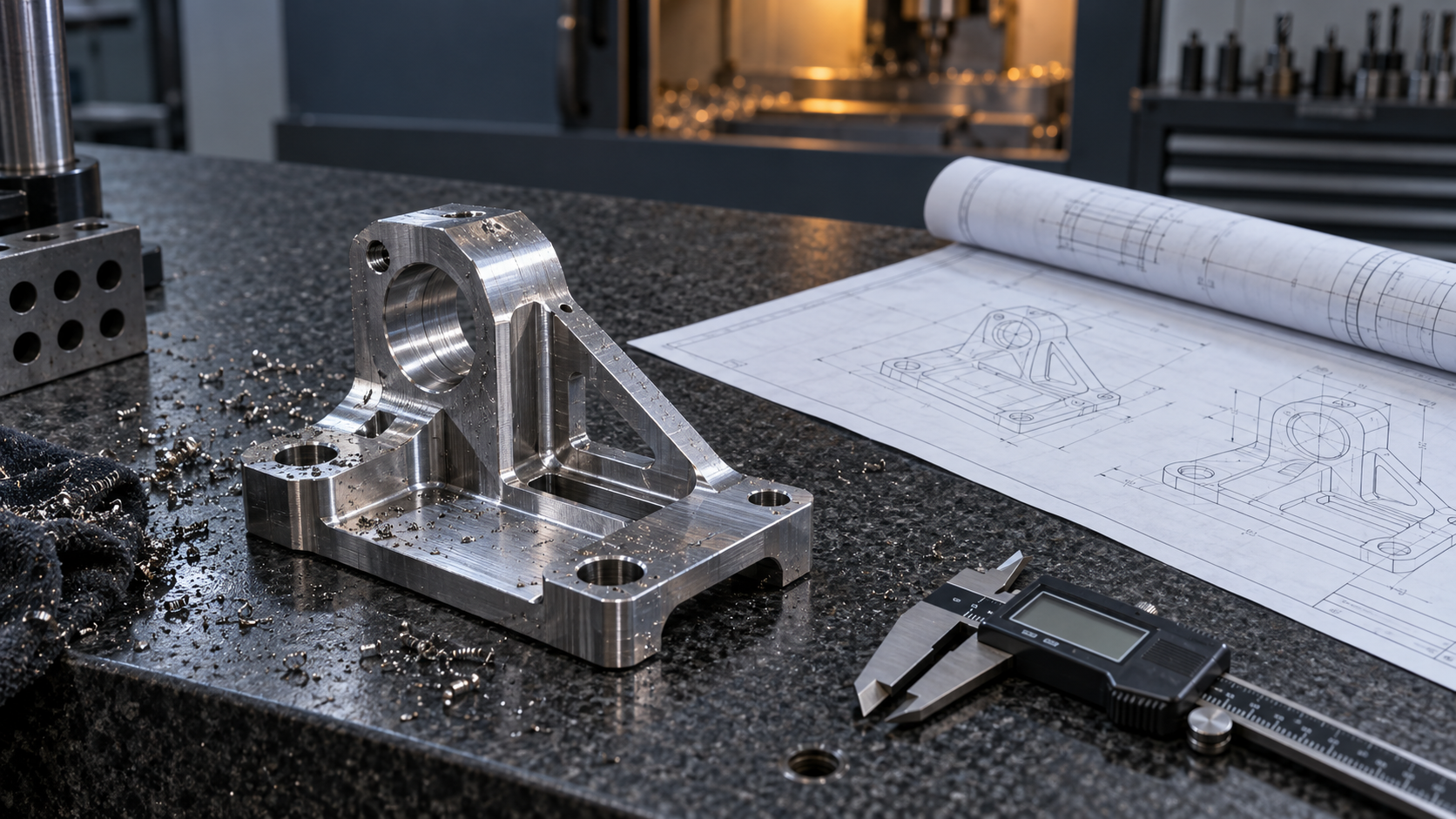
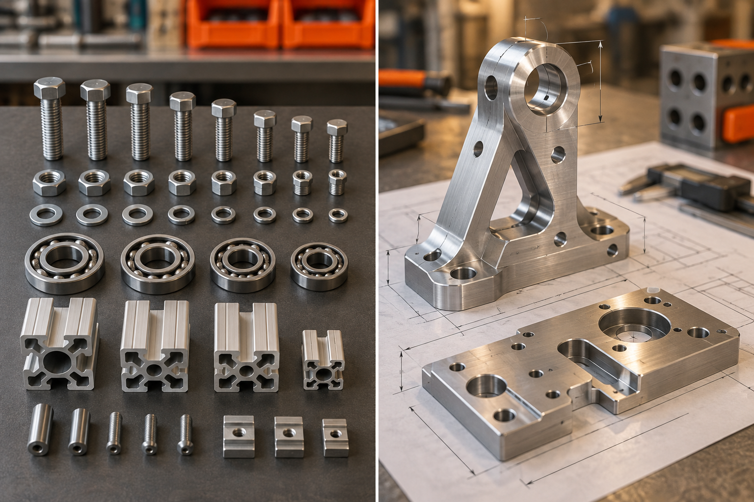
What is the difference between standard parts and non-standard parts: a one-sentence definition and three common misjudgments
Screws, bearings, profiles, flanges—most people can state their specifications off the top of their heads and find their national standard numbers in a handbook. But when it comes to non-standard part machining, many buyers and engineers become vague: what exactly counts as non-standard? Does a one-off part count as non-standard? Is the precision necessarily higher?
Let's first clean up the definition. Non-standard parts are a concept proposed in contrast to standard parts, referring to parts for which the state has not established strict standard specifications and parameter regulations, which are independently controlled by enterprises, and which are customized according to customer drawings or requirements. Standard parts have unified size series, tolerance grades, and material grades; no matter who makes them, they are the same. Non-standard parts do not have this set of public constraints. Their shape, tolerance zone, surface roughness, and heat treatment state are all written in drawings or technical agreements and agreed upon by both supplier and buyer.
Misjudgment 1: Non-standard equals one-off
Non-standard means "there is no public standard to apply," not "only one can be made." For a connecting plate on a certain type of automation equipment, the drawing is issued by the company itself and cannot be found in national standards, but thousands of them may be made in a year. Conversely, a stepped shaft turned according to national standard dimensions is still a standard part even if only one is made. Batch size and whether something is standard are two different things; don't mix them together when deciding who should make it.
Misjudgment 2: Non-standard equals high precision
Among non-standard parts, some have strict requirements on mating surfaces, while others are only for support and are sufficient with tolerances as loose as ±0.5 mm. Precision is given by the drawing, not inherent in the word "non-standard." Assuming that non-standard means high precision can easily inflate expectations during quoting and can also make designers afraid to relax tolerances on non-functional surfaces.
Misjudgment 3: Non-standard equals no standard to follow
The fact that national standards do not specify a size series does not mean there is no standard in the manufacturing process. The dimensional tolerances, geometric tolerances, surface roughness, material grade, and heat treatment requirements on the drawing are the "standard" for this non-standard part. Inspection is also carried out accordingly: calipers, micrometers, CMMs, roughness testers—measure whatever needs to be measured. The real trouble is not "no standard," but incomplete drawings, where the two parties each have their own understanding of which surface is the datum and which dimension is critical. Most of the risk in non-standard part machining arises here, not from being "non-standard" itself.
How to classify non-standard parts: machining differences between metal and non-metal non-standard parts
The most practical way to classify non-standard parts is by material: metal and non-metal. This division is not academic fussiness; it directly determines process chain length, fixturing method, tool selection, and final cost. The same drawing, changed to a different material, may differ substantially in quote, and the reason lies exactly along this dividing line.
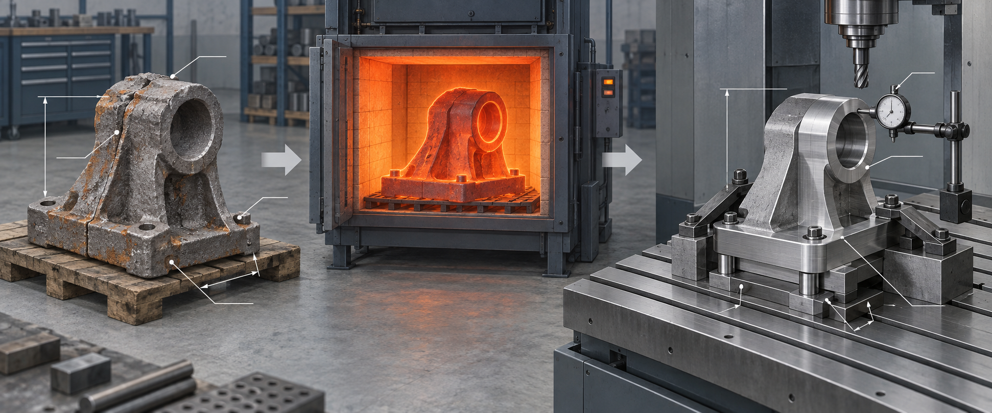
Metal non-standard parts: where the variables lie from blank to finishing
Metal non-standard parts usually start from castings, forgings, or bar stock and proceed all the way to finishing. Along this chain, there are far more control points than for non-metals. Heat treatment causes deformation, cutting introduces residual stress, welding changes local microstructure, and before surface treatment one must also consider substrate adhesion. Each step can cause dimensional drift, which means each step must leave allowance and a re-inspection window.
Typical metal non-standard parts such as piston retaining rings, hydraulic fixtures, and guide rail seats have interface dimensions determined by the complete machine and cannot use ready-made standards. Such parts often require multiple operations of rough machining—stress relief—semi-finishing—finishing, and in between may also require wire EDM or die-sinking EDM to handle hard materials or clean corners. More operations mean more setups, and the risk of cumulative error rises accordingly.
This is also the core reason why metal non-standard parts usually cost more than standard parts: not because the material is expensive, but because of complex processes, many variables, and high quality control costs. Standard parts can use dedicated machines and assembly lines, while each batch of non-standard parts may involve re-setting tools, re-programming, and re-validating fixtures.
Non-metal non-standard parts: moisture absorption, warping, and brittle fracture are the main contradictions
Non-metal non-standard parts cover engineering plastics, acrylic, composite materials, and more. They do not need to worry about cutting stress release, but they have their own troubles: moisture absorption and swelling, post-machining warping, brittle fracture at thin walls, and dimensional springback caused by thermal deformation. For example, POM and nylon are sensitive to humidity and need drying before machining; acrylic tends to chip when drilled, so feed and speed must be kept under control.
Such parts are commonly found in insulating boards, fairings, sensor brackets, and panel-type parts. Their tolerance zones are usually wider than those of metal parts, but the requirements for surface appearance and assembly flatness are not necessarily lower. When selecting materials, consider operating temperature, whether chemicals are contacted, and whether a flame-retardant rating is required—these are often indicated on the drawing by only a material grade, yet in practice they affect machining methods and post-processing.
It should be noted that although non-metal non-standard parts have relatively shorter process chains, material batch variation is sometimes more obvious than with metals. Sheets of the same grade from different batches may have different internal stress states, and the amount of warping after machining will therefore differ. For slightly larger batches, it is recommended to trial-cut one or two pieces first to confirm the deformation pattern before proceeding.
The logic for choosing between the two material types in non-standard part machining
When choosing metal or non-metal, first look at function: load-bearing, wear-resistant, temperature-resistant, and conductive generally go with metal; insulation, lightweight, corrosion resistance, and cost sensitivity suggest non-metal. Then look at batch size: for small batches of metal non-standard parts, CNC milling and turning are more flexible; for small batches of non-metals, CNC or 3D printing can be used, and the latter has clear advantages when shapes are complex and tooling is not desired. Finally, look at assembly: for non-metal parts mating with metal parts, the difference in thermal expansion coefficients must be taken into account; otherwise they may assemble at room temperature but seize once heated.
Regardless of the category, clearly marking material state, heat treatment requirements, surface treatment, and critical tolerances on the drawing is the prerequisite for making the quote and lead time for non-standard part machining predictable. If the material column says only "steel" or "plastic," the supplier can only guess, and the cost of rework ultimately returns to the requester.
What is custom machining of non-standard parts: machining methods and their corresponding process capabilities
Custom machining of non-standard parts is the process of completing operations such as cutting, forming, and joining on manual, semi-automatic, or automatic machine tools according to drawings or requirements. It is not a specific process, but a collection of processes—the same drawing may go through CNC milling or vacuum casting and duplication molding, depending on batch size, precision level, and material. Below, each method is broken down, and each one's suitable application is pointed out.
Subtractive: CNC milling and turning, EDM, wire EDM
Subtractive machining is the mainstay of custom machining of non-standard parts. CNC milling and turning are suitable for precision forming of metals and engineering plastics, from one-off to small batch, with changeovers relying on programs rather than molds. Electrical discharge machining (EDM) handles hard materials and sharp corner cleaning, and electrode wear and discharge gaps must be compensated for in the process. Wire EDM is used for hardened steel, inserts, and narrow slots; its precision and surface integrity are usually better than those of fast wire EDM, but cutting speed is slow, making it suitable for final finishing or direct forming.
The industry often says "CNC equipment precision on the order of 0.0025 mm," which refers to capabilities such as machine positioning and repeat positioning, not the actual measured tolerance of the part. How much the part can ultimately achieve depends on fixturing rigidity, tool runout, cutting heat, and measurement method; the specific result is subject to the drawing and actual measurement.
Equal-material and additive: 3D printing, vacuum casting and duplication
3D printing (FDM, SLA, SLS, MJF, DMLS, etc.) mainly handles two types of work for non-standard parts: structural verification and shapes that are difficult to produce by subtractive machining. It eliminates fixturing and tool paths, but anisotropy, support marks, and dimensional drift must be factored into tolerances in advance. Prototype duplication (vacuum casting) suits small-batch trial production, using silicone molds to reproduce parts at the 20–50 piece level. The surface and material feel are close to injection molding, and it is far cheaper than cutting a steel mold, but mold life is limited and dimensional stability is inferior to injection molding.
Forming and batch replication: sheet metal stamping, bending, welding, injection molding
Sheet metal work combines stamping, bending, and welding to form enclosures, brackets, and connecting plates, and suits non-standard structural parts made from sheet stock. Bend springback, weld heat distortion, and cumulative hole-position error are common control points, and the first article must be compared against a checking fixture or 3D scan. Injection molding takes a different path: it requires a mold, and the per-piece cost is amortized as batch size grows, so it is only cost-effective when the batch is large enough and the part shape allows draft and uniform wall thickness. Forcing a mold when the batch is too small usually makes the unit price and lead time higher than those of a standard part product.
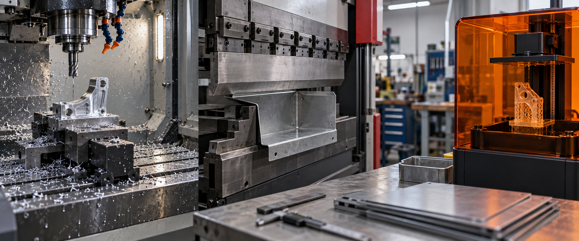
To choose which method to use, the order of judgment is batch size, precision, material, and only then equipment. Choose the wrong method, and the subsequent fixturing, inspection, and rework all go wrong with it. To see the specific process capability boundaries, refer to the descriptions of CNC machining capabilities, 3D printing capabilities, sheet metal capabilities, and injection molding capabilities.
Five major categories of custom non-standard parts machining equipment: how buyers and engineers should choose
Before choosing equipment, answer two questions first: what precision does this batch of non-standard parts require, and how large is the batch. Get the order wrong, and you end up milling a bracket that only needs drilling on a five-axis machine, or forcing an ordinary milling machine to chew through an IT6-grade mating surface. The five major equipment categories—welding, cutting, machining machinery, inspection, and auxiliary post-processing—are the skeleton of selection, but how to choose within each category depends on the part itself.
Welding and cutting equipment: look at material, thickness, and heat-affected zone
When selecting welding equipment, look at the base metal first. Carbon steel parts commonly use MIG/MAG or manual arc welding; stainless steel and aluminum alloy are sensitive to heat input, and TIG or laser welding can better control distortion. There are three decision points: whether the weld needs non-destructive testing, whether annealing or stress relief is required after welding, and whether the welding position is flat or all-position. All-position welding places higher demands on equipment flexibility and operator experience; for small batches, manual welding is more realistic, and robotic workstations can be considered once the batch grows.
Cutting equipment is classified by energy source: plasma, laser, waterjet, and flame. For thin sheet (commonly 0.5–3 mm), fiber laser is efficient and produces a small heat-affected zone; for medium and thick plate (6–25 mm), plasma is more economical; waterjet produces no heat effect and suits parts that have already been heat-treated or that have metallographic requirements at the cut edge, but it is slow and has high operating costs. The most commonly overlooked factor in cutting selection is the heat-affected zone (HAZ)—within a few millimeters of the cut edge, hardness and microstructure change, and any surface to be finish-machined later must be left with enough allowance to cut this layer away.
Machining machinery and equipment: travel, spindle speed, tool magazine, and fixturing method
This is the main battlefield of custom non-standard parts machining. Three-axis vertical milling suits plate-type parts and shallow pockets; parts with side holes or angled faces need a three-axis machine with a rotary table or a direct upgrade to four-axis; impellers, complex curved surfaces, and multi-face machining in a single setup are where five-axis comes in. When selecting, look at four parameters: X/Y/Z travel must cover the part envelope plus the fixture, spindle speed determines whether small tools (such as below φ0.5 mm) can reach a reasonable cutting speed, tool magazine capacity determines whether multi-operation parts require frequent stops for tool changes, and fixturing method determines whether thin-walled parts will be clamped out of shape.
The same applies to turning: short, stout shafts use ordinary CNC lathes, slender shafts require a follow rest or a Swiss-type machine, and parts with milling features depend on whether turn-mill capability can reduce secondary setups. The positioning accuracy of CNC equipment commonly cited in the industry is on the order of 0.0025 mm; this is a static specification of the equipment itself, and actual part precision also stacks tool wear, clamping stress, thermal distortion, and measurement error. Go by the drawing tolerances and measured reports, and do not treat equipment catalog specifications as guaranteed part values.
Inspection and auxiliary equipment: how to decide on CMM, 3D scanning, and deburring
Inspection equipment depends on what is specified on the drawing. If there are only linear dimensions and hole diameters, calipers, micrometers, and plug gauges are sufficient; if there are geometric tolerances such as position, coaxiality, and profile, a coordinate measuring machine (CMM) is needed. For full-dimensional comparison of the first article against the drawing and CAD model, or for scanning a used old part for reverse engineering, use 3D scanning. Decision points: whether the inspected features are regular geometry, whether the tolerance is less than one-third of the measurement equipment's uncertainty, and whether a data report must be issued.
Auxiliary equipment is easily treated as an add-on, but it actually affects lead time and yield. Deburring comes in several forms: manual, vibratory tumbling, electrochemical, and thermal energy. Burrs in cross holes and internal cavities cannot be reached by hand, so this must be stated in advance. For surface treatments such as cleaning, anodizing, black oxide, and sandblasting, either you have your own lines or you outsource them, and at the selection stage you must confirm whether the treatment will change dimensions—anodizing generally adds a few microns, so mating surfaces need allowance or protection.
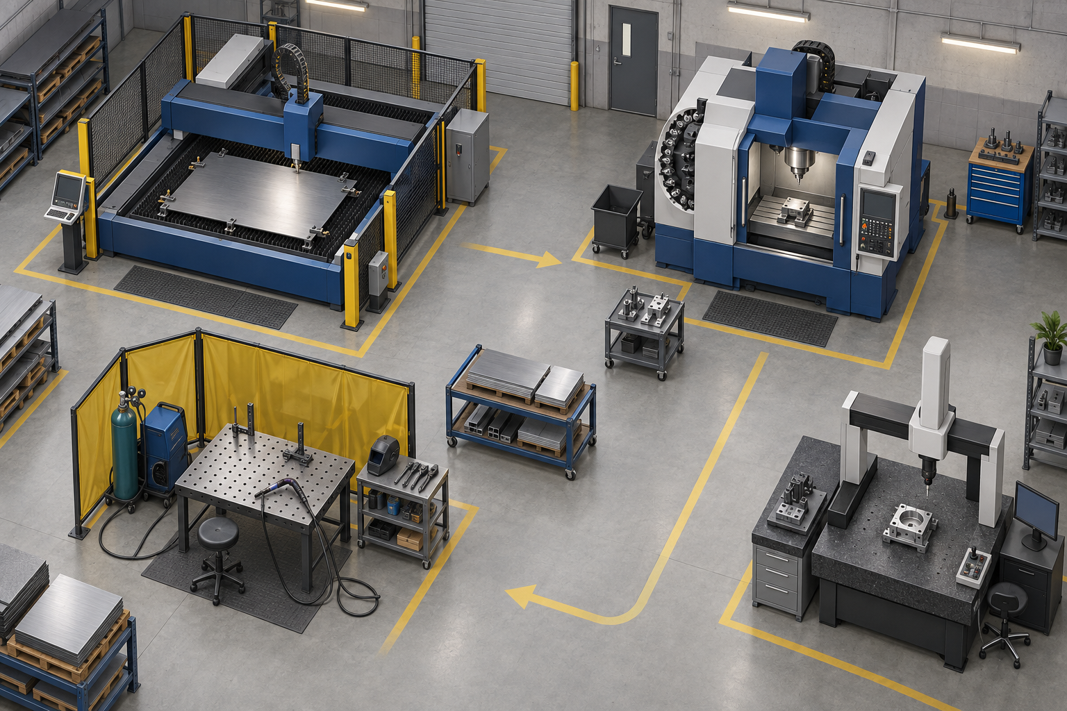
The order that links the five equipment categories together is: first determine precision and batch size → then determine the process route → finally determine the equipment. For the same batch of non-standard parts, as the batch grows from 5 pieces to 500, the machining equipment may change from a three-axis machine plus a drill press to dedicated tooling plus multi-axis machines; inspection may change from sampling to full inspection plus SPC. Equipment is the result, not the starting point.
Processes and steps for custom non-standard precision parts: from requirements analysis to shipping
There is no fixed paradigm for non-standard parts machining, but the process chain is stable. The only difference is whether certain intermediate steps are done and how deeply. Below is a walkthrough in the actual order of flow, pointing out the key control points and the most common causes of rework at each step.
Requirements analysis and design confirmation
First confirm where the part is installed, what it mates with, and what loads it bears. If this step is not done thoroughly, everything afterward is wasted. Common rework: the 2D drawing and 3D model are inconsistent, version numbers do not match, or the customer verbally changed a dimension but the drawing was not updated. After confirmation, freeze one version of the drawing, and all subsequent operations use it as the sole basis.
Material selection and pretreatment
Select material according to the working conditions, not the more expensive the better. For aluminum parts, look at the alloy grade and temper; for steel parts, look at whether quenching and tempering or pre-hardening is required. Pretreatment is often skipped: stress-relief annealing of bar stock, leveling of plate, and drying of non-metallic parts to remove moisture. Skip this step, and the part distorts after finishing and goes out of tolerance. Common rework: the material condition is wrong, hardness fails after machining, and the part can only be scrapped and remade.
Drawing and tolerance review
Go through every dimension: which are functional dimensions that must be tight, and which are general tolerances that can be relaxed. Datums must be unified, and geometric tolerances and dimensional tolerances must not conflict. Roughness requirements must be written clearly, with Ra values corresponding to different machining methods. Common rework: tolerances are specified too tightly to be machined, and revising the drawing later wastes time; or datums are not unified, so inspection does not match up.
Fixturing plan and process route
First determine the number of setups, then sequence the operations. The more setups, the greater the cumulative error. Faces that can be completed in one setup should be done in one setup as much as possible. The process route should clearly state the allowance allocation for roughing, semi-finishing, and finishing. Common rework: excessive clamping force on thin-walled parts causes springback after unclamping and dimensions drift; or the operation sequence is reversed and finished surfaces are scratched by subsequent operations.
Grinding, rough machining, and electrical discharge machining
Surfaces that require high-precision datums are ground first to provide a foundation for subsequent locating. Rough machining removes allowance, leaving uniform allowance for finishing. Electrical discharge machining (EDM) is used for hard materials or complex cavities, and for deep narrow slots and corner cleanup. Wire EDM is used for high-precision contours and cutting after hardening. Common rework: uneven roughing allowance causes sudden tool load changes during finishing and unstable dimensions; or EDM parameters are not set well, the recast layer is too thick, and the subsequent grinding allowance is insufficient.
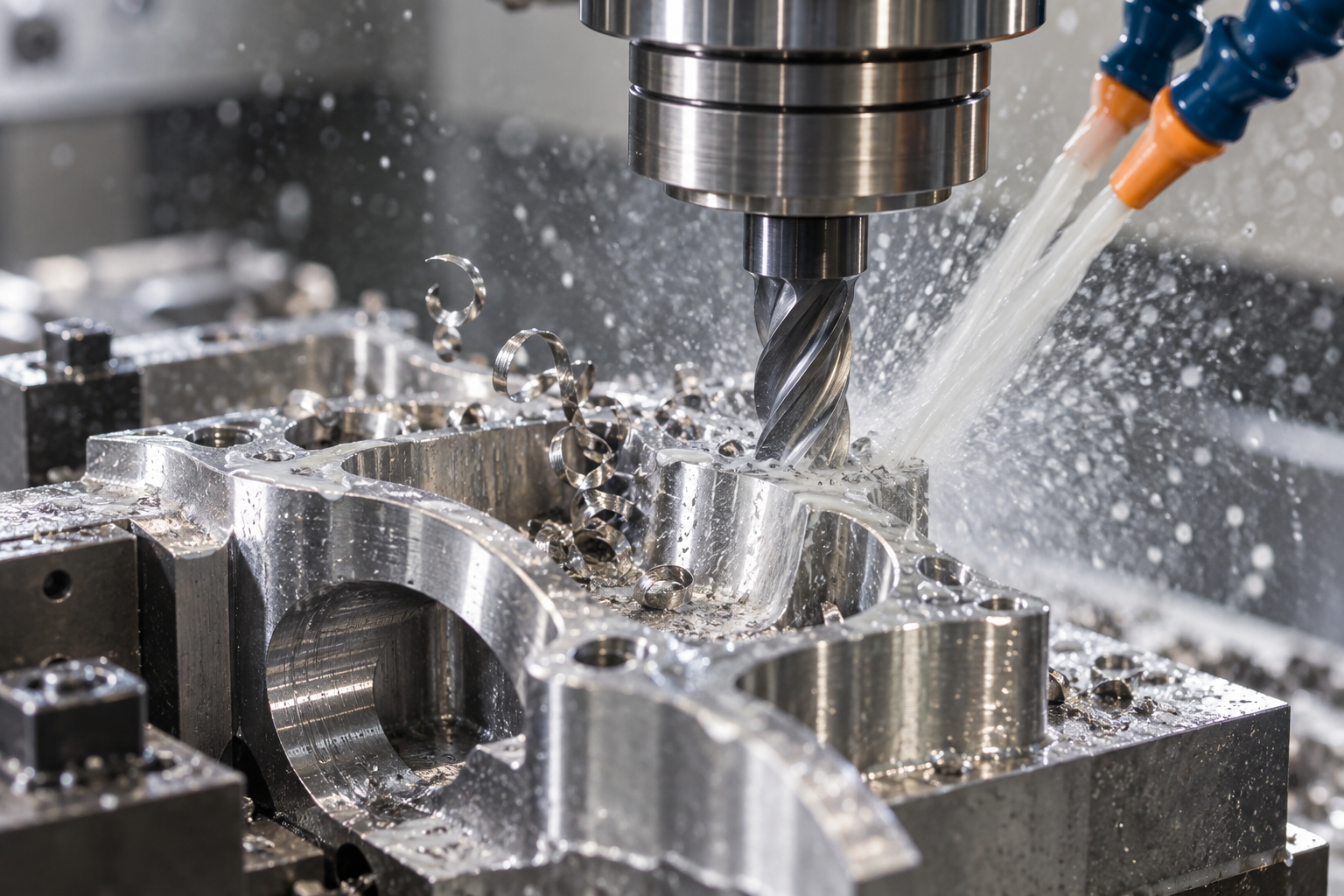
CNC finishing and deburring
Finishing is controlled according to the drawing tolerance band, tool wear must be monitored, and the first article must be inspected. Do not leave deburring to the end: cross holes, thread openings, and slot edges all need to be gone over. Common rework: burrs are not fully removed and scratch mating surfaces during assembly; or deburring chamfers too much and removes functional edges.
Quality inspection, packaging, and shipping
Quality inspection measures each item against the drawing: dimensions, geometry, and roughness. Critical dimensions are compared using a CMM or 3D scanning, and ordinary dimensions with gauges. Inspection reports travel with the shipment. Packaging is chosen according to part characteristics: protective film on precision surfaces, anti-rust oil on parts prone to rust, and support for thin-walled parts. Common rework: an inspection item is missed and out-of-tolerance is only discovered at the customer; or improper packaging damages precision surfaces in transit.
After-sales traceability relies on process records: material batch, process parameters, inspection data, and operator. If a problem arises, it can be traced back to which step. The value of non-standard parts machining is not how fast a single piece is made, but that every step in this chain is controllable, traceable, and reproducible.
How to Use DFM to Control Non-Standard Part Machining Costs: Find the Root Cause at the Design Stage
For non-standard parts, the bulk of the cost is already determined the moment the drawing is finalized. Material utilization, number of setups, required tooling and operations, and inspection methods are all tied to the part's shape and tolerance bands. By the time a process engineer gets the drawing and starts looking for ways to save money, there is very little room left to maneuver. What DFM (Design for Manufacturing) does is identify the root causes of cost before any metal is cut. It doesn't promise a percentage savings; it answers one question: is this feature worth making?
First Ask "Why Does This Feature Exist?"
When you get a non-standard part drawing, go through every feature one by one: is this step there to clear space for assembly, or is it just a design habit? Is this R0.5 internal fillet necessary, or was it drawn casually? Marking a non-functional surface as ±0.02 instead of ±0.1 has no effect on assembly, but the machining and inspection costs differ by a tier. The first step of DFM isn't changing the design—it's putting "design intent" and "machining cost" on the same table for comparison. Most of the cost of non-standard part machining gets stuck on those features that no one can explain why they exist.
Six Actionable Cost-Reduction Directions
- Simplify the part shape and reduce the number of setups. When a part goes from being machined on three sides to two, you save not only the flipping time but also the positioning errors and scrap risk from re-aligning. If a profile can be cut directly from stock profile, don't design it as something that requires hogging out a large block.
- Match the material to the working conditions, not the most expensive one. 6061 is enough for structural parts that don't contact corrosive media; there's no need to go to 7075 or 316L. For non-standard parts, the extra cutting time and tool wear from choosing a higher-grade material are often more expensive than the material price difference.
- Standardize components and tooling. Converge thread specifications and hole diameter series to a few common ones as much as possible to reduce tool changes and programming setup; parts that can be completed on the same machine with the same batch of tools are easier to control in both scheduling and cost.
- Loosen tolerances on non-functional surfaces. Only mating surfaces, locating surfaces, and sealing surfaces need to be tightened; the rest can follow general tolerances. Marking the entire drawing as ±0.02 will multiply inspection time, while the benefit may be zero.
- Avoid hard-to-machine features. Deep cavities, narrow slots, thin walls, and internal square corners that can't be cleared will force the use of special tools, multiple setups, or even EDM. Wherever possible, change to an open structure, increase fillet radii, and leave tool clearance.
- Unify thread and hole specifications. If M3, M4, M5, and M6 all appear on one drawing, tapping and tool changes stack up; converging to two or three makes programming and machining rhythm smoother.
A Before-and-After Design Comparison
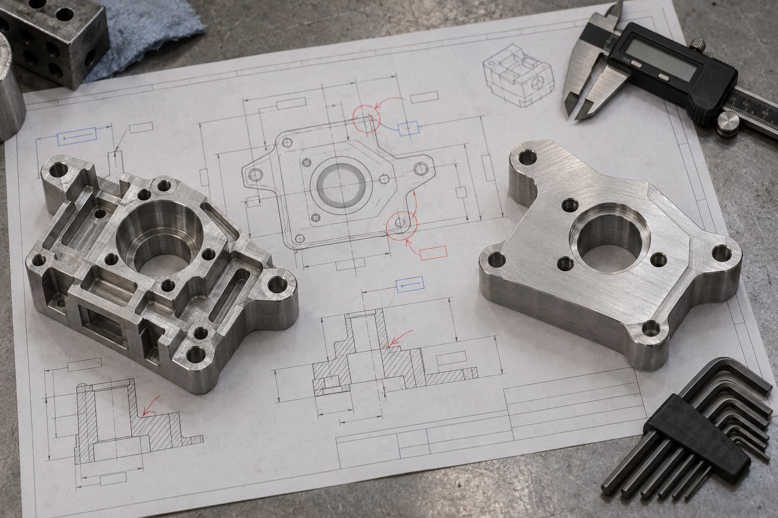
For a sensor bracket on some type of automation equipment, the original design was a special-shaped structure with a deep cavity milled from a single block of aluminum, requiring machining on the bottom and both sides, with an internal cavity depth-to-width ratio close to 4:1, requiring special long-length-to-diameter tooling and EDM to clear corners. Functionally, it only holds a sensor and ensures one mounting hole position. It was changed to a standard aluminum plate bent into an L shape, then milling the mounting face and external locating holes. The number of machined faces went from three to one, the deep cavity was eliminated, and the process was compressed from "milling—EDM—finishing" to "milling—bending." The part is slightly less rigid, but sufficient for that working condition. This is the typical benefit of DFM: not making a single operation faster, but reducing the number of operations themselves.
Approaches in the same direction are common in non-standard part machining: changing a structure that requires two pieces to be welded and then machined into one formed by a single milling operation; replacing a quenched and tempered part that requires heat treatment with a pre-hardened material that can be machined directly; changing high-precision mating holes from "drill—ream—grind" to "drill—ream," provided the tolerance band allows it. Which one to change depends on the part's true functional boundaries. If the design side is willing to clearly mark "which dimensions are functional dimensions and which are reference dimensions," cost and lead-time judgments for non-standard part machining will be more accurate. If you need to look at the direction based on a specific drawing, you can start with AI chat quoting or CNC machining capabilities, and explain the drawing together with the actual working conditions.
Common Application Areas and Typical Parts for Non-Standard Part Machining
Demand for non-standard part machining is highly concentrated: the more that interface dimensions are back-derived from the complete machine and the more that batch size cannot justify a dedicated mold, the more likely non-standard parts are involved. Conversely, scenarios that standard parts can cover are usually those where mating dimensions and load ratings have already been unified by the industry, so you can simply select them. Understanding this dividing line is more useful than memorizing a list of parts.
Automotive and Tooling: Parts Customized to Company Requirements, Such as Piston Retaining Rings and Hydraulic Fixtures
In automotive components, piston retaining rings, hydraulic fixtures, and dedicated gauges are typical non-standard parts. The reason is not complicated: they must match existing piston assemblies, hydraulic circuits, and production line stations, and hole spacing, step height, and mating tolerances are all determined by the complete machine or the fixture body itself. No national standard can specify them in advance. These parts often have small batch sizes and uncomplicated structures, but they have high requirements for dimensional consistency and assembly interchangeability.
Tooling and fixtures illustrate the point even better: when the same equipment switches to a different product, the fixture may need to be remade, and opening a dedicated mold is simply not cost-effective. Therefore, this type of non-standard part machining usually uses CNC milling and turning, supplemented by wire cutting or EDM when necessary, with materials ranging from 45 steel and aluminum alloy to stainless steel.
Automation Equipment and Electronics: Guide Rail Seats, Connection Plates, Sensor Brackets, Insulating Parts
Guide rail seats, connection plates, and sensor brackets in automation equipment are another major source of non-standard part machining. Their function is very clear: to fix standardized guide rails, cylinders, and sensors to the equipment frame, while the frame's hole positions, stroke, and mounting angle differ for every machine, so these transition parts must be customized. In terms of precision, the flatness of the mounting surface and hole position tolerances are often key, while the outer shape can be relaxed.
Non-standard parts in the electronics direction tend to be non-metallic: insulating plates, flow guide covers, heat dissipation structural parts, and test fixtures. They focus more on the material's electrical insulation, thermal conductivity, flame retardant rating, and warping after machining, rather than strength like metals. CNC milling from engineering plastics, or vacuum casting for small batches, are both common choices.
Medical, Laboratory Equipment, and New Energy: Small Batches, Many Interfaces, Fast Model Changes
Stainless steel fixtures, instrument housings, and sample racks in medical and laboratory equipment are almost all non-standard parts: the equipment itself has low production volume, and matching parts are even less likely to have standard models; at the same time, they must meet usage conditions such as cleanliness, corrosion resistance, and no dead corners, with materials mostly selected from 304 and 316 stainless steel or engineering plastics such as PEEK and POM.
The new energy direction mainly involves battery module structural parts, such as end plates, brackets, and connector positioning parts. Their interfaces are determined by cell dimensions and module layout, while cell specifications are still iterating rapidly, making injection molding risky, so CNC or sheet metal is generally used first in the early stages.
To summarize why these scenarios tend toward non-standard: interface dimensions are determined by the complete machine, so standard parts don't match; batch size is insufficient to amortize dedicated mold costs; and they must also fit existing assemblies and existing equipment. To judge whether a part should be made non-standard, just see whether it hits all three of these conditions at the same time. If you need to evaluate which process a specific part should use, you can first look at the manufacturing capabilities overview, then confirm against the drawing.
Frequently Asked Questions About Non-Standard Part Machining (FAQ)
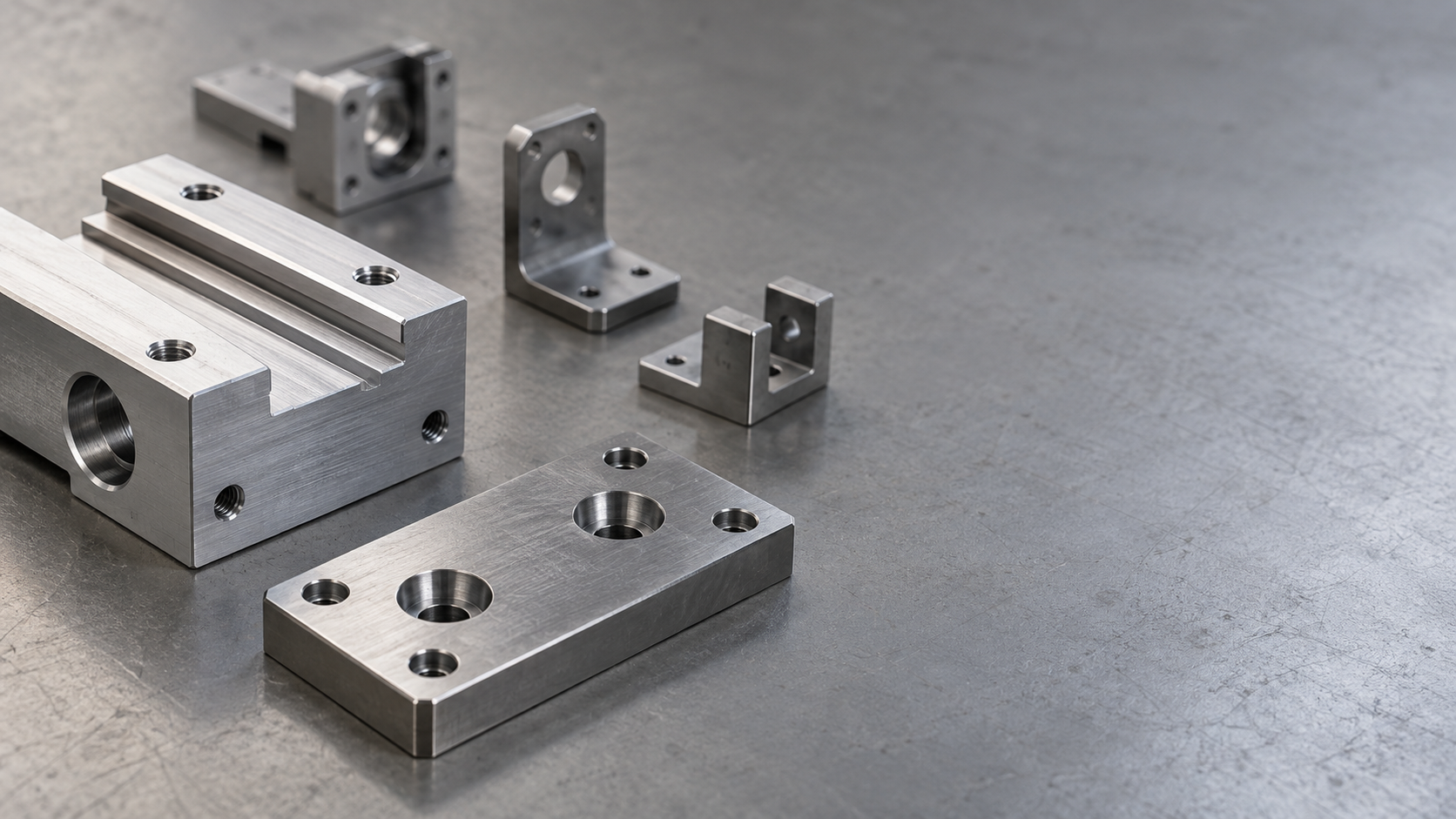
The questions below are basically the points where procurement and engineers most often get stuck when going through the non-standard part machining process. The answers only address the definitions, classifications, equipment, processes, and DFM discussed in this article, and do not involve specific quotations or lead times.
How Do You Decide Whether a Part Should Be Made as a Non-Standard Part or Directly Selected as a Standard Part?
First check whether the interface and function can be covered by an existing standard part. If the mounting dimensions, stroke, load, material, or connection method do not match standard part specifications, or if the standard part still requires secondary modification after installation, then go with non-standard part machining. Conversely, as long as you can select a standard part with matching specifications and sufficient service life and precision, give priority to the standard part—its interchangeability, procurement cycle, and unit price are usually more controllable. The boundary for judgment is: non-standard parts solve "the part of the need that standard parts cannot cover," not "customize whenever you want."
How High a Precision Can Non-Standard Part Machining Achieve? If the Drawing Specifies 0.005mm, Can It Definitely Be Achieved?
You can't generalize. The positioning accuracy of common CNC equipment in the industry is on the order of 0.0025mm, and some precision parts can actually reach around 0.002mm in measurement, but this is a typical industry value, not a guarantee that any part, any material, or any batch size can achieve it. Whether it can be achieved depends on the material, structural rigidity, clamping method, tooling, measurement means, and batch size. If the drawing specifies high-precision requirements, first have the supplier conduct a DFM review to confirm the datum, tolerance band, and inspection plan before discussing whether it can be accepted. Tolerances marked that cannot be achieved will only turn into disputes in the end.
Why Is the Cost of Non-Standard Part Machining Usually Higher Than That of Standard Parts?
Three reasons stack up. First, there are no ready-made molds and fixtures, so programming, clamping plans, and first-article trial cuts all require separate investment. Second, the process chain for metal non-standard parts from blank to finishing is long, and heat treatment deformation, cutting stress, and surface treatment all need to be controlled separately, with many variables. Third, batch sizes are small, so setup time accounts for a high proportion per piece. Standard parts reduce unit cost through batch size and standardization, while non-standard parts do not have this condition, so being expensive is structural, not a matter of suppliers quoting arbitrarily.
What Should Be Clearly Marked on a Drawing So That Non-Standard Part Machining Quotations Go Smoothly?
At minimum, mark all of the following: material grade and condition, key dimensions and tolerance bands, datums, geometric tolerances, surface roughness, heat treatment and surface treatment requirements, and quantity. For parts with mating relationships, mark the mating dimensions and clearances. The more items are missing, the more the supplier can only quote based on the most conservative process, and the price will actually be higher. In addition, tolerances on non-functional surfaces can be appropriately relaxed, concentrating the precision budget on dimensions that truly affect assembly and function, which will make the quotation more realistic.
For small-batch non-standard parts, should you choose CNC machining or 3D printing?
It depends on the application and material. If you need load-bearing capability, threads, fit precision, or metal, prioritize CNC machining; if the structure is complex, there are many internal channels, the batch is only a few pieces, and high strength is not required, 3D printing is more cost-effective. For small batches of plastic parts, you can also consider vacuum casting for duplication; the surface and feel are closer to injection-molded parts than printed parts. If the same batch of parts includes both metal load-bearing parts and plastic housing parts, separating them and using different processes is often more economical than forcing them into one.
Key takeaways
- The core difference between standard parts and non-standard parts is whether there are unified national specifications and parameter regulations. Non-standard parts are customized based on drawings or requirements, with tolerances and surface finish specified by the customer.
- Non-standard parts are divided by material into two major categories: metal and non-metal. Metal parts have longer process chains and more quality control points, and their costs are usually higher than standard parts.
- Custom machining equipment for non-standard parts can be divided into several major categories such as welding, cutting, and machining machinery. Machining methods include manual, semi-automatic, and automatic, and selection must match batch size and precision.
- The process chain for non-standard precision parts begins with requirements analysis and design confirmation, then goes through material pretreatment, grinding, EDM, CNC machining, and finally quality inspection and packaging. Every step must leave traceable records.
- The value of DFM is to identify the root causes of cost before the first cut, reducing expensive later modifications by simplifying shapes, selecting materials reasonably, and standardizing components.



