
What Is Heat Treatment for Parts? Why It Is Not Just About Making Parts Harder
Heat treatment of parts is the controlled heating, soaking, and cooling of metal to change its internal microstructure and properties. It is generally not intended to change the macroscopic shape of a part, but rather to adjust its hardness, strength, toughness, wear resistance, cutting machinability, and dimensional stability. Although the part may look the same externally, its internal microstructural condition may have changed.
These changes result from the cooling path and temperature cycle, not simply from raising the temperature. Under specific materials and conditions, rapid cooling may form martensite, increasing hardness and strength; slower cooling may produce microstructures better suited to cutting or impact loads, such as pearlite, or may form bainite within a specific process window. Changes in microstructure bring performance benefits but also create new risks: increased hardness is often accompanied by reduced toughness, while excessively rapid cooling may increase residual stress, distortion, and the tendency to crack.
Therefore, the objective of heat treatment for parts cannot be stated simply as “increase hardness.” Gears may require a wear-resistant surface and stable tooth geometry; shafts require strength, fatigue performance, and dimensional stability; and subsequent grinding or finish machining must also be considered. For parts subjected to impact, excessively high hardness may not necessarily be an advantage. For thin-walled parts or parts with uneven wall thickness, the performance target must also be established together with the allowable distortion range.
The same set of heat treatment parameters cannot be directly applied to the same material grade in every case. Effective thickness, cross-section changes, sharp corners, holes and slots, loading method, and areas exposed to loads and wear all affect the internal temperature gradient and cooling response of a part. When selecting a process, first define the target microstructure and properties, then consider the material, geometry, subsequent machining, and dimensional requirements as part of a single process decision. Heat treatment should not seek to maximize one individual metric, but to achieve a verifiable balance between performance benefits and the risks of distortion and cracking.
The Three Control Points in a Part Heat Treatment Cycle: Heating, Soaking, and Cooling
Heat treatment of parts is not simply a matter of placing a part in a furnace and then cooling it rapidly; it is a control chain consisting of heating, soaking, and cooling. These three stages determine whether temperature gradients are controllable, whether microstructural transformations are sufficient, and whether the final properties and distortion risks can meet requirements. Heating temperature is only one parameter; heating rate, temperature differences within the furnace, and loading method are equally important.
Heating: First Control Temperature Differences and Thermal Stress
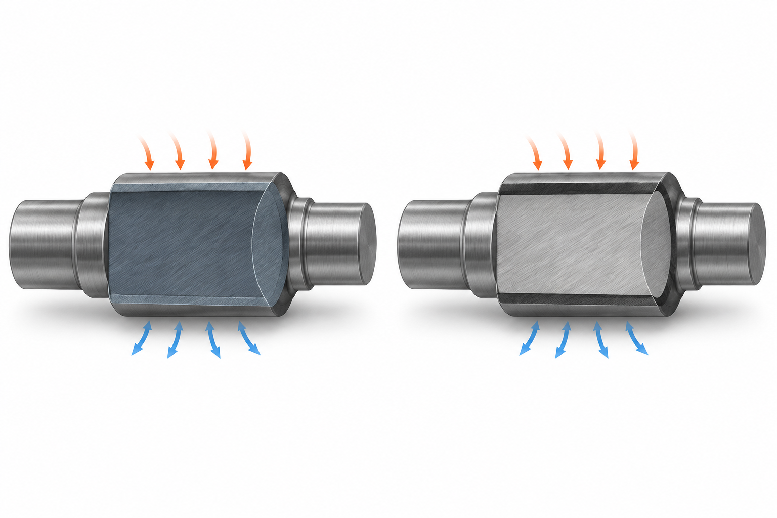
When the part surface heats before the core, areas with variations in thickness, sharp corners, and holes or slots are prone to developing temperature gradients. Excessively rapid heating may concentrate thermal stress, causing warping, localized cracking, or subsequent dimensional drift. Shafts, thin-walled parts, and parts with uneven wall thickness generally cannot use the same heating strategy; the loading quantity, spacing between parts, and furnace atmosphere also affect the actual heating conditions.
Soaking: Determined by Effective Thickness and Loading Conditions
The purpose of holding is not simply to wait, but to make the temperature across the part’s cross-section more uniform and allow sufficient time for the expected microstructural transformation to complete. Holding time is generally affected by the material composition, effective thickness, loading method, furnace type, and heating medium, so a single fixed value cannot be specified for all parts. Insufficient holding may result in inconsistent microstructures between the surface and interior; excessive holding may increase the risks of grain growth, oxidation and decarburization, or dimensional changes.
Cooling: The Rate Determines the Microstructure and the Risks
Cooling rate changes the phase-transformation path: for a given material and temperature condition, rapid cooling may form martensite, while slower cooling may form pearlite or bainite. The former is generally beneficial for increasing hardness and strength, but it also increases the risks of residual stress, distortion, and cracking; the latter may improve toughness or dimensional stability, but may not meet wear-resistance requirements. Water, oil, polymer, and salt baths have different cooling intensities, so the medium should be selected according to the material, cross-section, and geometry.
For example, a process example for certain 42CrMo shaft components uses quenching heating at approximately 850°C, with stepped heating or a lower heating rate to reduce thermal stress. The temperature, holding time, and calculation coefficients in this example apply only to specific materials, structures, and equipment and cannot be generalized as universal standards for all shaft components.
Annealing, Normalizing, Quenching, and Tempering: How to Distinguish Heat Treatment Processes for Parts
There is no absolutely “best” heat treatment process for parts. The key is to match the material, cross-sectional dimensions, loading conditions, and performance objectives. When evaluating the options, start by asking three questions: How is it done, what microstructure or properties does it primarily change, and what manufacturing problem does it solve?
| Process | How it is done | Primary function | Typical applications and limitations |
|---|---|---|---|
| Annealing | Slow cooling after heating, commonly furnace cooling | Reduce hardness, relieve residual stress, and improve ductility and machinability | Suitable for improving the machining condition or preparing for subsequent heat treatment; because cooling is slow, the objective is generally not to obtain high hardness |
| Normalizing | Air cooling after removal from the furnace | Refine and homogenize the microstructure and achieve higher strength and hardness than annealing | The cooling rate is generally between furnace-cooled annealing and rapid quenching; the result depends on the material and part dimensions |
| Quenching | Rapid cooling after heating to an appropriate temperature | Promote the formation of a microstructure with high hardness and strength, often involving martensitic transformation | Suitable for wear-resistant and load-bearing applications; excessively rapid cooling increases the risk of residual stress, distortion, and cracking |
| Tempering | Typically reheated after quenching, followed by controlled cooling | Reduces quench brittleness, restores some toughness, and adjusts the balance between hardness and strength | It cannot simply be omitted; a common industry range is approximately 150–650℃, but the specific temperature must comply with the material, target microstructure, and process sheet |
Annealing and normalizing: first address machinability and microstructural uniformity
Annealing uses slower cooling to bring the microstructure closer to an equilibrium state. It is commonly used to reduce hardness, relieve some machining or casting stresses, and improve subsequent machinability. Normalizing uses air cooling, which is faster and generally helps refine grains, improve microstructural nonuniformity, and enhance the balance of strength and toughness. Neither process can be evaluated independently of the material grade and effective thickness; for parts with significant thickness differences, the actual cooling rate and resulting microstructure may not be uniform.
Quenching and tempering: performance trade-offs in part heat treatment
Quenching increases hardness and strength through rapid cooling, but the increase in hardness is often accompanied by reduced toughness, increased thermal stress, and dimensional changes. Water quenching is generally more severe than oil quenching, and the risks of distortion and cracking are often higher; the choice of medium should not be based solely on the idea that “higher hardness is always better.” Tempering is typically scheduled immediately after quenching to reduce brittleness, relieve some residual stress, and restore toughness. Final acceptance should not be based on a single hardness point; the part’s application should also be considered when checking hardness distribution, critical dimensions, and the required microstructural condition.
How quenching media change the hardness and distortion of heat-treated parts
Quenching media are not used simply to pursue faster cooling. They determine the cooling intensity, temperature gradient, and rate of microstructural transformation as a part transitions from high to low temperature, thereby affecting hardness, toughness, residual stress, distortion, and the risk of cracking. Part heat treatment should first define the target hardness and loading conditions, then select the medium based on the material, cross-sectional dimensions, and geometry.
Differences among water quenching, oil quenching, and polymer quenching
Water quenching is generally more severe than oil quenching and makes it easier to achieve higher hardness, but thermal and transformation stresses are often greater as well. Shaft parts with significant changes in cross-section may develop bending, ovality, or local cracking; parts with sharp corners, keyways, and hole edges are more likely to develop defects first at stress concentrations. Oil quenching provides relatively gentler cooling and is often used where the risk of distortion needs to be reduced, but the actual result still depends on the material’s hardenability, oil temperature, agitation, and loading condition.
The cooling capacity of polymer quenching can be adjusted through concentration, temperature, and flow conditions, so its effectiveness cannot be judged solely from the name “polymer.” Changes in concentration, fluid aging, or inadequate circulation can all alter the cooling conditions at the part surface. During process validation, attention should be paid to hardness and dimensional changes in different regions rather than simply recording the quench-tank fluid type.
How salt baths control temperature differences and transformation risks
Salt baths can be used to reduce the temperature difference between a part’s surface and core and, in specific processes, to control cooling and microstructural transformation. This does not mean that all parts will achieve lower distortion; the material composition, effective thickness, salt-bath temperature, transfer time, and part loading method still require verification. Thin-walled parts may distort due to rapid heat loss, while parts with uneven thickness may develop residual stress because different regions respond differently during cooling.
Therefore, the selection of a quenching medium should be based on three outcomes: whether the hardness reaches the target, whether distortion remains within the allowable range, and whether the microstructure is uniform. Water, oil, polymer, and salt baths do not have an absolutely superior order of preference. For critical shafts, thin-walled parts, and parts with sharp corners, the heat-treatment plan should also specify the fixturing or loading method, cooling conditions, remeasurement of critical dimensions, and any necessary crack inspection, to avoid mistaking the highest hardness for the most suitable process.
Surface hardening and through-hardening: part geometry determines process suitability
Part heat treatment does not necessarily require the entire cross-section to reach high hardness. If a part requires both a wear-resistant surface and a tough, impact-resistant core, surface hardening is often more suitable than through-hardening; if consistent strength and microstructure are required throughout the part, an overall heat-treatment route should be considered. The basis for selection is not the process name, but the load-bearing areas, wear locations, effective thickness, geometry, and allowable distortion range.
Induction heat treatment: balancing localized hardening and overall thermal effects
Induction heat treatment rapidly heats the surface or specified areas using an inductor, followed by quenching to form a localized hardened layer. It is suitable for wear-prone areas such as tooth flanks, journal surfaces, and cam working surfaces, as well as for parts where minimizing the overall thermal cycle is desirable. The actual result depends on the inductor profile, frequency, heating time, scanning speed, part curvature, and quench-fluid delivery method. Holes, sharp corners, steps, and abrupt changes in thickness alter electromagnetic coupling and heat-dissipation conditions; hardening depth or distortion cannot be inferred from the material grade alone.
Carburizing and nitriding: define the case depth first, then assess the core and dimensional stability
Carburizing is typically used to obtain a relatively deep, high-carbon surface layer, followed by quenching and tempering to form a hard surface and a tough core; nitriding forms a nitrided layer at a lower temperature and is commonly used for surfaces requiring wear resistance, fatigue resistance, or stringent dimensional stability. Industry references commonly cite process temperatures of approximately 850–950°C for carburizing and 480–580°C for nitriding. These values can only serve as general references and cannot replace material standards or process validation. The actual方案 must also verify case depth, core strength, sharp corners and thin-wall areas, as well as requirements for dimensional remeasurement after heat treatment. Surface hardening is not a matter of “the higher the hardness, the better”: excessive case depth, an unsuitable gradient, or uneven local cooling may cause spalling, cracking, or changes in mating dimensions.
Inspection of Parts After Heat Treatment: What Else Should Be Checked Besides Hardness?
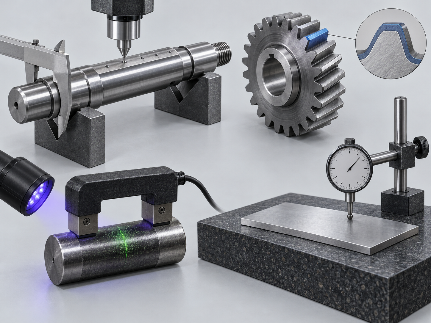
Acceptance of heat-treated parts cannot be based on a single hardness value. Hardness measurement points should be determined in conjunction with the drawing, material grade, and service location, with the measurement positions, surface condition, and hardness distribution recorded. On the same part, edges, centers, tooth surfaces, or journals may respond differently to cooling; too few measurement points can easily conceal local soft spots, overheating, or abnormal hardness gradients.
When necessary, hardness inspection should be combined with metallographic examination, crack detection, and remeasurement of critical dimensions. Metallography is used to confirm whether the microstructure meets the target, while surface or internal crack inspection identifies risks arising from quenching stress, sharp-corner effects, and material defects. Dimensional inspection after heat treatment should focus on drawing features such as diameter, length, flatness, circular runout, and concentricity; it should not be limited to remeasuring a single overall dimension.
- Shaft Parts: Focus on journal dimensions, circular runout, concentricity, bending, and the distribution of hardness along the length.
- Gear Parts: In addition to tooth-surface hardness, confirm the tooth profile, lead, effective hardened-layer or case depth, and deformation after heat treatment.
- Thin-Walled and Sharp-Corner Parts: Give priority to checking warpage, localized excessive hardness, cracks, and clamping contact areas; sharp corners, hole edges, and transitions between thick and thin sections are generally more sensitive.
- Parts with Uneven Wall Thickness: Compare the microstructure, hardness, and dimensional changes at different cross-sections and in critical areas, adding representative measurement points when necessary.
Acceptance criteria should be specified in advance in the drawing or process documentation: target hardness or hardness range, measurement-point locations, microstructure requirements, permissible deformation, and whether crack, metallographic, or hardened-layer inspection is required. If finish machining will follow heat treatment, the machining allowance before heat treatment must be distinguished from the final dimensions to avoid mistaking insufficient machining allowance for heat-treatment deformation.
When discussing a heat-treatment方案 for a part, it is recommended to provide the material grade, part drawing, effective thickness, assembly and load-bearing areas, wear areas, target hardness or microstructure, and permissible deformation range at the same time. The more complete the information, the easier it is to establish a verifiable process loop linking performance targets, inspection items, and deformation risks.
FAQ: Common Heat-Treatment Issues for Parts
Heat treatment of parts cannot be assessed independently of the material grade, cross-sectional dimensions, loading arrangement, and target performance. The following questions address common process boundaries involving quenching, cooling media, and acceptance inspection.
Why are parts usually tempered after quenching?
Quenching can increase hardness and strength, but rapid cooling may also produce a relatively brittle microstructure and introduce residual stress, deformation, or even cracking risks. Tempering is generally scheduled after quenching to adjust hardness, toughness, and dimensional stability through controlled reheating. The tempering temperature should be determined according to the material, target microstructure, and service load; a single universal value should not be applied directly.
Can the same heat-treatment parameters for parts be applied directly to the same material?
They cannot be applied indiscriminately. Shafts, gears, thin-walled parts, and parts with uneven wall thickness made from the same material grade may have different effective thicknesses, sharp corners, clamping conditions, and heat-dissipation conditions, resulting in different heating, soaking, and cooling responses. Heat-treatment parameters should also be confirmed with consideration of the furnace type, loading quantity, target hardness or microstructure, and permissible deformation range.
Is water quenching necessarily better than oil quenching?
Not necessarily. Water quenching is generally more severe than oil quenching and may provide a higher cooling intensity, but it also typically carries greater risks of distortion, residual stress, and cracking. Oil, polymer, or other media should be selected based on the material's hardenability, part cross-section, and geometry; “higher hardness is always better” is not a complete basis for process evaluation.
Does heat treatment acceptance for parts only require hardness testing?
Normally, a single hardness point should not be the only consideration. The measurement locations and hardness distribution should be confirmed according to the drawing and intended application. Where necessary, the metallographic structure, cracks, critical dimensions, circular runout, flatness, concentricity, and distortion after heat treatment should also be inspected. For surface-hardened parts, requirements related to the hardened layer or case depth should also be clearly defined; the specific combination of inspections depends on the part's function and quality standards.
Key takeaways
- The primary changes produced by heat treatment are changes in the internal microstructure and properties, not simply making a part “harder after heating.”
- Heating rate, effective thickness, adequacy of soaking, loading method, and the cooling curve jointly determine the heat treatment result.
- Annealing is primarily used to improve machinability and relieve stress, normalizing to homogenize the microstructure, quenching to establish hardness, and tempering to reduce quench brittleness.
- Water, oil, polymer, and salt-bath quenching provide different cooling intensities. The hardness target must be evaluated together with distortion, residual stress, and cracking risks.
- Heat treatment acceptance cannot rely on a single hardness reading; it should also consider hardness distribution, microstructure, cracks, distortion, and remeasurement of critical dimensions.



