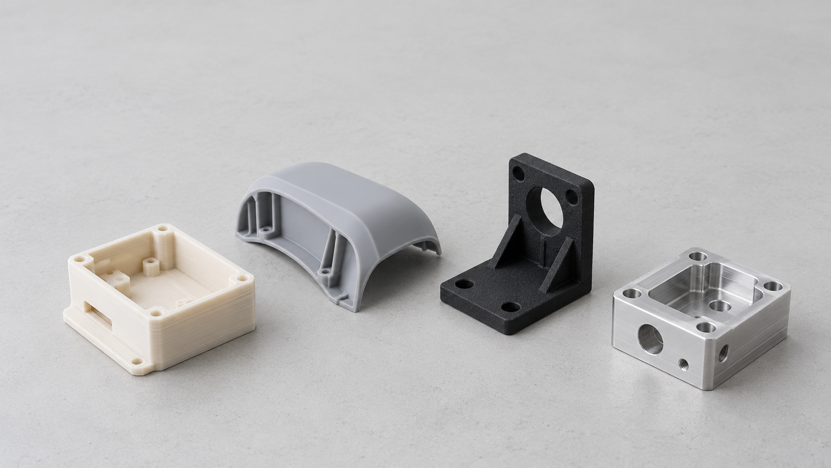
Rapid Prototyping Is Not a Single Process: First Define What the Prototype Must Validate
The same CAD file does not necessarily require the same prototype process for appearance review, snap-fit assembly, and load testing. The value of rapid prototyping technology lies not only in quickly producing a model, but also in using the appropriate prototype to answer a specific engineering question: Are the dimensions correct? Can the parts be assembled? Do the appearance and details meet expectations? Or can the structure withstand the specified loads and environment?
Match Rapid Prototyping to the Validation Objective First
If the only checks are enclosure proportions, hole locations, and hand feel, an early rapid prototype is usually sufficient to support a design review. If fine textures, transparency effects, or appearance coatings must be evaluated, surface details and post-processing become the primary requirements. Snap-fits, hinges, threads, and internal channels require attention to material, print orientation, wall thickness, powder removal, or support removal. When load-bearing capacity, heat resistance, fatigue, or long-term ultraviolet exposure is involved, the differences between the prototype material and the final production material must be evaluated separately.
- Dimensional and Assembly Validation: Focus on datums, hole locations, tolerance chains, and assembly interference.
- Appearance and Detail Validation: Focus on surfaces, textures, transparency, support marks, and post-processing condition.
- Functional and Durability Validation: Record the material, build orientation, load, temperature, number of cycles, and failure criteria.
- Production Similarity Validation: Check whether the prototype represents the material and process characteristics of subsequent CNC-machined, vacuum-cast, or injection-molded parts.
Therefore, when selecting a rapid prototyping process, the first input is the validation objective, the second is the material, environment, and load, and only the third is cost and delivery schedule. A prototype can support only conclusions that match its process conditions; the results of an appearance prototype cannot be directly extrapolated to the performance of a production part. Subsequent reviews should also retain the CAD version, process material, post-processing details, and inspection methods so that prototype issues can be converted into production design inputs.
How to Select a Rapid Prototyping Process: Comparing FDM, SLA, SLS/MJF, and Machining Methods Based on Validation Objectives
The choice of rapid prototyping process depends first on what question the prototype needs to answer: checking dimensions and assembly, or evaluating appearance details, load-bearing performance, or the look and feel of production materials. The same CAD file may require prototypes made using multiple processes. The layer thicknesses in the table below are only typical ranges; actual results are also affected by the equipment, material, build orientation, process parameters, and post-processing.
| Dimensions, assembly, and larger conceptual models | FDM; common thermoplastics; layer thickness of approximately 100–300 μm | Lower cost and material requirements make it suitable for rapid iteration | Layer lines, support marks, warping, and anisotropy between layers may affect hole positions, snap-fits, and datum surfaces | Can represent the overall form and provide an initial assembly check, but generally cannot directly represent injection-molded surface quality or strength |
| Appearance, fine features, transparent or highly detailed models | SLA; photopolymer resin; layer thickness of approximately 25–100 μm | Details and surface quality are generally better than with FDM, making it suitable for appearance reviews | Requires washing, support removal, sanding, or post-curing; the resin may be relatively brittle | Can support evaluation of proportions, textures, and human–machine tactile experience, but should not be directly extrapolated to the durability of thermoplastic parts |
| Complex structures, functional nylon parts, and small-batch prototypes | SLS/MJF; powdered nylon; layer thickness of approximately 80–150 μm | Unfused powder provides support, making it suitable for internal cavities, lattices, and complex snap-fits | Powder removal is required; particle surface texture, porosity or density, dimensional consistency, and powder batch must be checked | Relatively suitable for validating functional trends, but not equivalent to injection-molded nylon parts |
| Critical dimensions, actual engineering materials, or higher surface quality | CNC; metals or engineering plastics | The material and local dimensions are closer to those of machined parts | Clamping, tool accessibility, thin walls, and complex internal cavities can constrain the design | Highly useful as a reference for machined production parts, but must be considered together with datums and inspection methods |
| Small quantities of appearance models, assembly-feel prototypes, or samples made from materials similar to those used in production | Vacuum casting; elastomeric or polyurethane casting materials | Suitable for producing small quantities of replicas, with appearance and tactile feel that can be brought closer to the target part | The master pattern, parting lines, draft angles, and material differences can affect the results | Can be used for appearance and assembly verification at specific stages, but cannot replace a stable injection molding process |
Therefore, the value of rapid-prototyped parts lies not in “which process is best,” but in whether the process supports the intended conclusions. When real-load, temperature, or long-term durability data are required, the material system, orientation, post-processing, and test conditions should be recorded, and options such as CNC machining, vacuum casting, or injection molding that more closely resemble the target process should be considered.
FDM rapid prototyping is suitable for early dimensional and assembly verification, but do not overlook print orientation
FDM rapid prototyping forms parts by heating and melting thermoplastic filament, then stacking material layer by layer along the sliced toolpaths. Its equipment and material requirements are generally relatively low, making it suitable for rapidly iterating larger conceptual housings, brackets, and mounting prototypes. If the current need is only to confirm overall proportions, hole relationships, assembly clearances, or hand-held dimensions, FDM is often sufficient, without the need to adopt a more complex process from the outset.
However, the results of FDM prototypes depend heavily on print orientation and process parameters. Interlayer bonding gives the parts pronounced anisotropy, so strength along the Z axis, snap-fit opening and closing life, and thin-wall bending resistance may differ from those in the XY plane. Removing supports may also leave burrs or local notches; holes, threads, and datum surfaces often require cleaning, drilling, reworking, or light sanding before assembly. Warpage of the bottom surface can affect housing fit, sealing surfaces, and measurement datums.
Print orientation and assembly datums in rapid prototyping
Therefore, FDM rapid prototyping is better suited to answering whether “the dimensions and assembly are basically viable.” Unqualified appearance or load results should not be directly extrapolated to injection-molded part performance. At a minimum, verification records should specify the material, print orientation, layer height, infill method, support strategy, and post-processing condition. For snap-fits, threads, or load-bearing connections, the load direction and number of cycles should also be recorded, and drawings should distinguish between dimensions adjusted after printing and dimensions in the as-formed condition.
- Conceptual housings and larger parts: first check proportions, hole locations, assembly clearances, and interference.
- Functional connectors: confirm the print orientation first, then determine whether the wall thickness, fillets, or test plan need to be changed.
- Appearance reviews: layer lines, support marks, and sanding condition should be stated clearly to avoid treating the FDM surface directly as a production appearance.
SLA rapid prototyping is suitable for appearance and fine-detail verification: what can resin prototypes demonstrate?
SLA rapid prototyping uses liquid photopolymer resin and forms parts by curing it layer by layer through exposure. Compared with FDM, which typically has more visible layer lines, SLA is generally better suited for verifying small text, chamfers, textures, thin walls, and curved transitions. Product managers can use it to review housing proportions, visual details, and human-machine feel, while structural engineers can first check fine snap-fits, button openings, and assembly clearances.
What questions are SLA rapid-prototyped parts suitable for answering?
If the questions are “Is the appearance harmonious?”, “Are the details clear?”, or “Can the part fit into the housing?”, SLA prototypes can usually provide valuable guidance. Transparent or translucent resin can also assist in evaluating the appearance concept and internal layout, but its transparency, color, and finish may not match those of the final material. The delivery condition of the prototype must be clearly specified, because support removal, cleaning, sanding, dyeing, and post-curing can all change surface roughness, edge condition, and local dimensions.
Resin prototypes cannot be directly equated with injection-molded parts
Standard photopolymer resin may be relatively brittle, and the degree of post-curing can also affect hardness and dimensional stability. Therefore, SLA appearance prototypes can support conclusions about proportions, details, and preliminary assembly, but they cannot automatically demonstrate the impact resistance, fatigue performance, heat resistance, long-term UV resistance, or cyclic life of injection-molded thermoplastic parts. If load testing is required, record the resin grade, print orientation, post-curing conditions, load direction, and failure criteria. If the test results will be used for production decisions, CNC-machined, vacuum-cast, or injection-molded samples made from materials closer to the target material should also be used for confirmation.
Which functional prototypes and low-volume parts are suitable for SLS and MJF rapid forming
SLS and MJF rapid forming are commonly used for complex nylon functional parts that require a certain level of mechanical performance. Unfused powder provides support during the forming process, so complex internal cavities, lattices, curved channels, living hinges, and functional snap-fits do not require supports to be designed for every overhanging area as they would with FDM or SLA. This design freedom is suitable for verifying assembly, motion interference, and preliminary load performance, and is also commonly used for low- to medium-volume trial production.
How SLS and MJF rapid forming affect prototype results
A typical process includes building the model, arranging part placement, powder spreading or jetting, overall cooling, powder removal, and post-processing. Insufficient cooling may increase the risk of deformation; incomplete powder removal can affect internal channels, snap-fit clearances, and assembly; and the granular texture of the powder surface may also change the actual friction of sealing and sliding surfaces. Both SLS and MJF can be used for functional nylon parts, but specific density, strength, dimensional consistency, and surface condition depend on the equipment, material, part placement, powder management, and post-processing. They cannot be judged solely by the process name.
Powder removal, wall thickness, and inspection limits for rapidly formed functional parts
During design, check powder-removal paths, outlets for blind cavities, minimum wall thickness, hole diameters, and local reinforcement structures. An internal cavity from which powder cannot be removed may be formable but still unsuitable as a deliverable functional structure. Assembly verification should also clearly define hole locations, tolerance zones, and datums to avoid misidentifying rough surfaces or residual powder as design issues. Test records should include the material batch, part placement orientation, post-processing, critical dimensions, and load direction. SLS or MJF prototypes can support complex-structure and assembly verification, but they cannot be directly equated with injection-molded nylon parts. If the conclusions involve long-term fatigue, heat resistance, or production consistency, they must still be reconfirmed using the target production material and process.

From rapid prototyping to production transfer: What should be checked in a DFM/DFA review
Passing assembly tests with a rapid-formed prototype does not mean it can enter production directly. The materials, load conditions, and forming limitations of 3D printing, CNC machining, vacuum casting, and injection molding differ. Production transfer should begin with a DFM/DFA review rather than sending the print file directly to the manufacturing plant.
Check structural changes first when transferring rapid-formed parts to production
First verify the wall thickness, fillets, thin-wall areas, and local reinforcing ribs. CNC machining is suitable for verifying actual engineering materials, critical dimensions, and surface quality, but tool diameter, fixture accessibility, deep cavities, and thin walls will constrain the design; complex internal cavities may require splitting the part or using another process. When switching to injection molding, also add draft angles, parting lines, ejector locations, shrinkage, and warpage assessments. Vacuum casting is suitable for validating small quantities of models and appearances or material tactility close to production, but parting and demolding must also be considered.
Rapid-formed prototypes cannot replace production-tolerance and assembly reviews
- Check whether snap-fits, hinges, threads, inserts, and fastening methods are suitable for the target process, and avoid judging them solely by the local elasticity of the printed part.
- Re-establish datums, tolerance stacks, and fit clearances, and confirm that shrinkage, deformation, and surface-treatment thickness will not cause assembly interference.
- Clearly define the measurement methods, inspection fixtures, or CMM datums for critical dimensions; prototype files cannot replace production drawings that specify materials, processes, and inspection requirements.
After the review is complete, create a design-change list and then produce first articles or low-volume samples for validation. Record the CAD version, target material, process, critical tolerances, assembly condition, and inspection results to determine which conclusions from the rapid-formed prototype can be retained and which must be reconfirmed under the production process.
How to turn prototype validation results into production decision records
The value of rapid-prototyping samples lies not only in confirming whether a part “can be made,” but also in converting dimensional, assembly, and functional test results into inputs for mass production. At the start of a project, the CAD revision, 2D drawings, tolerances, material, and validation objectives should be locked down before selecting a rapid-prototyping process. Appearance reviews, snap-fit assembly, and load testing may require different samples; one print file cannot replace all conclusions.
When communicating with suppliers, it is recommended to submit the CAD and drawing revisions, target quantity, material and environmental conditions, test loads or temperatures, measurement methods, and acceptance criteria together. Each design change should be linked to the corresponding failure mode and test results. Only records created this way can show what conclusions a rapid-prototyping sample supports, what risks remain, and provide a basis for production drawings, tolerances, and inspection plans. Defining the problem first, selecting the process next, and completing the transfer to mass production last is the only truly traceable project workflow.
Common Questions About Rapid-Prototyping Process Selection
What conclusions a rapid-prototyping sample can support depends on the validation objective, material, build orientation, and post-processing condition. The following questions focus on common limitations involving appearance, load-bearing performance, true production materials, and supplier communication.
Can an appearance prototype be used for load testing?
Generally, it cannot be used directly to determine the load-bearing capacity of a production part. An SLA appearance prototype may produce affected results due to resin brittleness, post-curing, and support marks; FDM parts are also affected by print orientation, interlayer bonding, and infill pattern. If testing is necessary, first confirm the material, orientation, post-processing, and load conditions, and limit the results to validation of the sample in that specific condition.
When should 3D printing be replaced with CNC machining?
CNC machining may be considered when critical dimensions, tolerances, surface quality, or actual engineering materials directly affect the conclusion. It is suitable for validating solid metal or plastic materials, datum surfaces, hole locations, and assembly fits, but complex internal cavities, thin walls, tool accessibility, and fixturing may limit the approach. Process selection must still be based on the part geometry and inspection requirements.
Can SLS or MJF parts directly replace injection-molded parts?
They should not be assumed to be equivalent. SLS and MJF are generally suitable for complex structures, functional nylon prototypes, and low- to medium-volume parts, but the surface texture, density, depowdering condition, and dimensional consistency of powder-bed-formed parts differ from the material condition, shrinkage, and parting conditions of injection-molded parts. They can support assembly and some functional validation, but durability, thermal-environment performance, and production-volume consistency should still be confirmed through the target injection-molding process.
What information is needed before requesting a quotation and DFM feedback from a supplier?
It is recommended to provide CAD files, 2D drawings and key tolerances, target material, quantity, operating environment, validation items, and test conditions, as well as specify appearance grade, mating components, and any thread or insert requirements. If samples already exist, also record the process, material, build orientation, post-processing, critical dimensions, and failure symptoms. The more complete the information, the easier it is for the supplier to provide effective recommendations regarding wall thickness, draft, parting, tolerance stack-up, and inspection datums.
Key takeaways
- The first input for rapid prototyping technology is the validation objective, not simply a comparison of equipment or printing speed.
- FDM is suitable for early-stage dimensional, assembly, and large-scale concept validation; the print orientation and interlayer strength must be documented.
- SLA is suitable for appearance and fine details, while SLS/MJF is suitable for complex structures and functional nylon prototypes, but neither can automatically represent the performance of injection-molded parts.
- CNC machining, vacuum casting, and injection-molded prototypes can more closely approximate subsequent products in terms of material, surface, or assembly feel, but the design must undergo simultaneous DFM/DFA review.
- Before production transfer, recheck wall thickness, draft angles, parting lines, shrinkage, inserts, tolerance chains, datums, and inspection methods.



