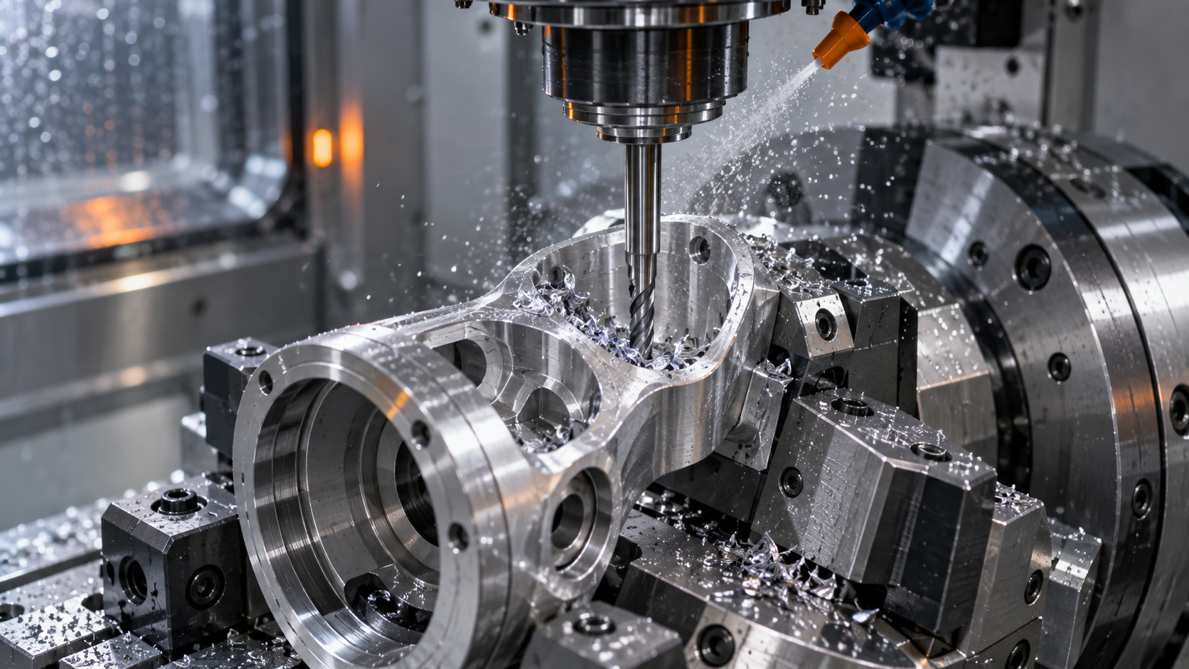
The root causes of precision problems in nylon injection molding: moisture absorption, crystallization, and shrinkage
The high precision and high quality of nylon injection molding are essentially a struggle with three things: moisture absorption, crystallization, and shrinkage. These three are not independent variables—moisture content changes melt viscosity and crystallization behavior, mold temperature determines crystallinity, and crystallinity in turn determines shrinkage rate and dimensional stability. If any link gets out of control, dimensional tolerances and appearance will drift.
The key variables affecting nylon injection molding precision can be listed as a short checklist: raw material moisture content, barrel temperature, mold temperature, injection speed, packing switchover point and packing curve, cooling time and cooling uniformity. Each variable has an operable window, and outside the window lie defects.
- Moisture absorption: PA6 and PA66 continuously absorb moisture from the air. If injection molding is done before adequate drying, the water in the melt vaporizes in the screw compression zone, directly producing silver streaks, bubbles, and dimensional variation.
- Crystallization: Nylon is a semi-crystalline polymer. High mold temperature gives high crystallinity and greater but stable shrinkage; low mold temperature gives low crystallinity and less shrinkage, but the risk of post-shrinkage and warpage rises.
- Shrinkage: Nylon shrinkage itself is relatively large and varies with wall thickness, glass fiber orientation, and gate position. Precision cannot be solved only by compensation with a single shrinkage rate.
Quality cannot rely only on machine adjustment to "cover" it; it must also be proven by inspection: first article dimensions, warpage, and process capability of critical dimensions are all bases for judging whether the process is stable. The high precision of nylon injection molding ultimately comes down to a reproducible parameter window plus a traceable inspection system, not some single "best parameter."
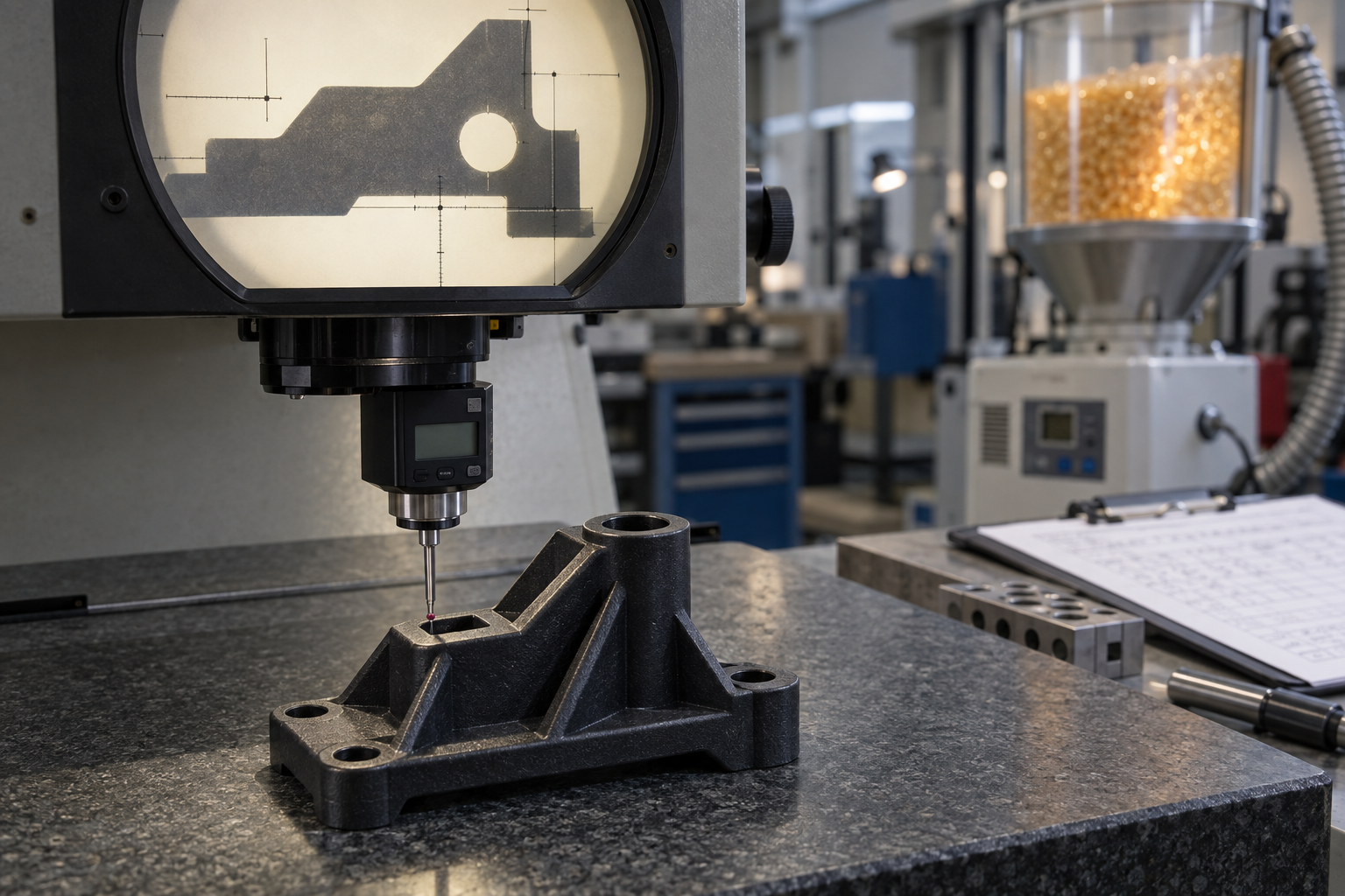
Material Drying and Moisture Content Control: The First Gate of Nylon Injection Molding
Nylon (PA6, PA66, PA46, PA12) has amide groups on its molecular chain, and these polar groups have an affinity for water molecules. Pellets absorbing moisture from the air is the starting point of all the trouble in this step. Feeding the barrel without thorough drying is equivalent to injecting water directly into the cavity.
The judgment is straightforward: to ensure high precision and high quality in nylon injection molding, moisture content must first be reduced. When drying is insufficient, the melt undergoes hydrolytic degradation in the screw, molecular weight drops, viscosity drops, and dimensions drift accordingly. The surface symptoms are silver streaks and bubbles, and the dimensional symptom is mismatch between batches.
Why dimensions become unstable when nylon is not dried adequately
Water vaporizes at the high temperature of the barrel. Part of it enters the cavity with the melt, forming bubbles and silver streaks; another part promotes hydrolysis, cutting the long chains. Once the molecular weight distribution changes, the shrinkage rate differs even with the same packing and the same cooling time.
Therefore, dimensional variation is often not a mold problem, nor an injection molding machine problem, but a dryer condition problem. Among the four variables—drying temperature, drying time, dew point, and material layer thickness—if any one is loosened, dimensional repeatability will drop.
How to set drying parameters: temperature, time, dew point
Common drying ranges in the industry: PA6/PA66 drying temperature about 80–100 °C, time 4–6 h; PA46 has a higher melting point, so the drying temperature can reach 100–120 °C, with the time extended accordingly. This is an in-process reference; the specifics must be confirmed according to the pellet supplier's drying curve and the workshop ambient humidity.
Desiccant dryers are more reliable than hot air dryers, and the dew point is usually required to be below −20 °C. If the material layer is thick, the hot air cannot pass evenly, and the inner layer is still wet. Dried material should be sealed and kept warm; exposed to air, it begins to regain moisture within tens of minutes.
| PA6 | 80–100 ℃ | 4–6 h | ≤0.10% |
| PA66 | 80–100 ℃ | 4–6 h | ≤0.10% |
| PA46 | 100–120 ℃ | 4–8 h | ≤0.05% |
| PA12 | 70–80 ℃ | 3–4 h | ≤0.10% |
| Glass fiber reinforced PA66 | 90–110 ℃ | 4–8 h | ≤0.08% |
The moisture content in the table is the target before the material enters the barrel. Glass fiber reinforced pellets have a rougher surface and absorb moisture faster, so sufficient drying time must be allowed. Moisture content can be spot-checked with a moisture analyzer; sampling at the dryer outlet is the most direct.

Treating drying as a fixed procedure rather than a state check is the most common mistake in nylon injection molding. High precision and high quality are not something you can adjust the machine to make up for; they are already largely determined at the drying step.
Mold temperature and crystallinity: the control knob for shrinkage in nylon injection molding
Nylon is a semi-crystalline plastic. After the melt enters the cavity, the molecular chains rearrange into crystalline regions. The degree to which this process is completed is determined by the cooling rate, and the cooling rate is directly controlled by the mold temperature. With a high mold temperature, crystalline regions grow fully, shrinkage is greater but consistent from batch to batch; with a low mold temperature, crystalline regions are incomplete, shrinkage is smaller but varies greatly from location to location, and warpage and dimensional drift follow. So when discussing precision in nylon injection molding, mold temperature cannot be avoided.
This is also the watershed in process thinking between nylon and non-crystalline plastics such as ABS and PC. For non-crystalline plastics, mold temperature mainly affects surface and flow, with a relatively mild effect on shrinkage; for nylon, mold temperature directly rewrites crystallinity, and thereby changes shrinkage, stiffness, and post-shrinkage behavior. With the same mold, changing the mold temperature from 60℃ to 90℃ can change molded dimensions by a few thousandths—for high-precision parts, that is already an order-of-magnitude difference.
Common mold temperature ranges for PA6 and PA66
Common industry mold temperature references: PA6 about 80–100℃, PA66 about 90–110℃; glass fiber reinforced materials usually take the upper end of the range, because glass fiber reduces flowability and increases melt viscosity, and a high mold temperature helps filling and reduces anisotropic shrinkage caused by glass fiber orientation. Thin-walled parts and long-flow-path parts also tend toward high mold temperatures. These are general process judgments, not guaranteed values; the recommended mold temperature for a specific grade should be based on the material supplier's property data sheet, then confirmed with mold trial results.
| Mold temperature strategy | Crystallinity | Shrinkage | Dimensional stability | Typical trade-offs |
|---|---|---|---|---|
| High mold temperature (upper end of range) | High, sufficient | Larger | Stable batches, low post-shrinkage | Longer cycle, good surface gloss, high energy consumption |
| Low mold temperature (lower end of range) | Low, incomplete | Smaller | Large positional differences, prone to warpage | Short cycle, but high risk of dimensional drift |
Effect of mold temperature on surface quality and post-shrinkage
When the mold temperature is low, the melt contacts the cold mold wall and freezes rapidly, forming a low-crystallinity "skin" on the surface layer. This skin is not entirely bad: it makes the surface glossier and more scratch-resistant, but when the interior continues to cool and shrink, the shrinkage difference between skin and core locks stress into the part. After demolding, the stress is released and the part slowly deforms—what is commonly called post-shrinkage. If a high-precision nylon part is measured only after sitting for a few days before assembly, what is measured may well no longer be the value it had right off the machine.
To suppress post-shrinkage, there are two approaches: first, increase the mold temperature so crystallization is completed as much as possible in the mold; second, perform annealing to release post-shrinkage in advance. Annealing temperature and time are determined by the material grade and part wall thickness, and are usually below the material's heat deflection temperature. For parts with tight dimensional tolerances, first confirm the measurement datum and measurement timing with the customer, then decide whether annealing is needed—otherwise the process and inspection sides will not match up.
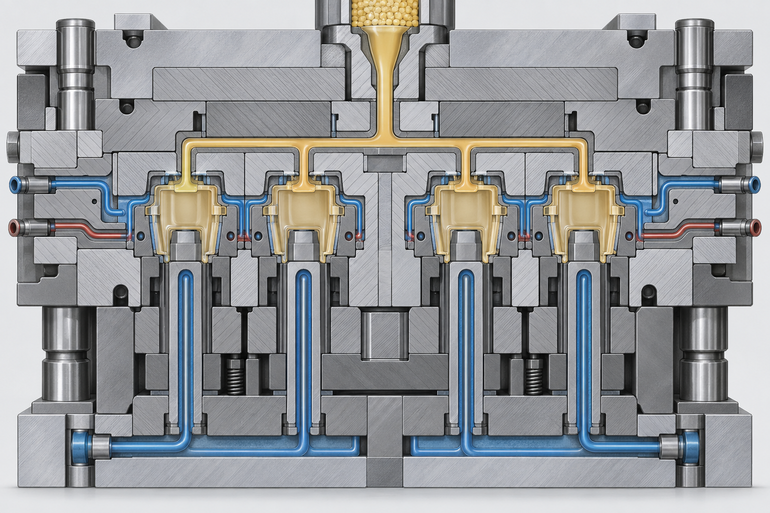
Mold temperature control circuit and uniformity
Mold temperature is not just "what temperature to set," but also "whether every point on the cavity surface is at the same temperature." If the temperature difference between the moving and fixed halves is too large, the two sides of the part shrink inconsistently, directly manifesting as warpage. Mold temperature controller selection depends on flow rate and temperature control accuracy, and water line layout must ensure sufficient flow velocity near the cavity and balanced circuits. Multi-point temperature measurement or in-mold temperature sensors can help determine the actual mold temperature distribution, rather than trusting only the displayed value of the mold temperature controller.
To judge on-site whether the mold temperature is adequate, first look at the appearance and dimensional trend of the first part: if dimensions at different positions within the same shot differ noticeably, or if dimensions drift in one direction over several consecutive shots, it is most likely uneven mold temperature or unstable temperature control. Stabilize the mold temperature first, then adjust holding pressure and speed—the order cannot be reversed.
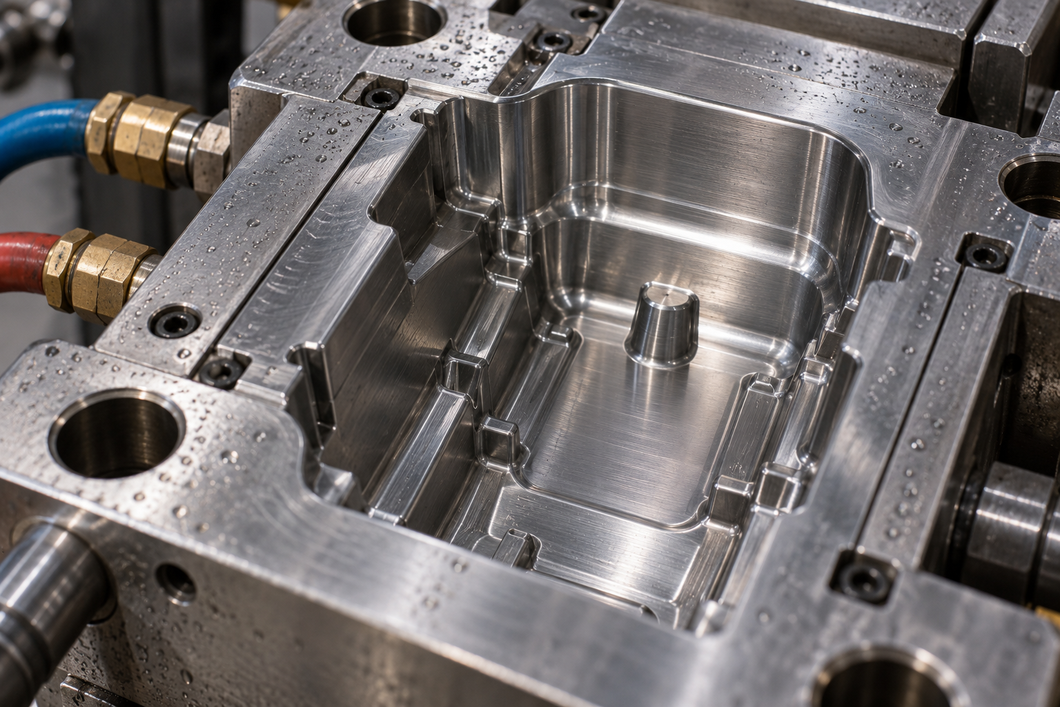
Injection Speed and Holding Pressure Curve: The Key to Dimensional Repeatability in Nylon Injection Molding
Whether the dimensions of nylon injection molding can be repeatable often does not depend on how well the mold is made, but on whether the curve in this section is stable. The four variables—speed, switch point, holding pressure, and holding time—constrain each other; adjusting one moves three.
Injection Speed: The Trade-off Between Shear and Orientation
Nylon melt has low viscosity and good flowability—this is an advantage and also a problem. If the speed is too slow, the front cools and filling is insufficient; if the speed is too fast, the shear rate at the gate spikes, molecular orientation becomes pronounced, and the directionality of shrinkage is amplified.
A common industry practice is multi-stage injection: low speed through the gate to avoid jetting marks and local overheating; medium-to-high speed in the middle section to ensure filling; and reduced speed in the final section to minimize flash. There is no universal answer for the specific speed values—it depends on wall thickness, flow-length-to-thickness ratio, and gate size—confirm according to the drawing and mold trials.
How to Determine the Holding Pressure Switch Point
The ideal switch point is the moment when "the cavity has just been filled and holding pressure has not yet begun," but in practice it is very difficult to pinpoint. There are three commonly used methods: position switch, pressure switch, and time switch. Position switch has the best repeatability, while pressure switch is more sensitive to viscosity fluctuations.
- Position switch: triggered by screw position; stable but requires first finding a suitable position through trials.
- Pressure switch: switches when cavity pressure reaches the set value; suitable for thin-wall, high-precision parts, but sensitive to melt temperature.
- Time switch: simple, but greatly affected by melt flow fluctuations; not recommended for parts with high dimensional repeatability requirements.
Holding Pressure and Holding Time: The Adjustment Knobs for Sink Marks and Dimensions
Holding pressure compensates for the volume lost to cooling shrinkage. If pressure is insufficient, sink marks appear and dimensions run small; if pressure is too high, internal stress is large, dimensions rebound after ejection, and the risk of flash rises. Typically start at 50%–70% of the filling pressure and gradually increase until sink marks just disappear.
Holding time must be long enough for the gate to freeze. If pressure is released before the gate freezes, the material in the cavity will flow back and dimensions will go out of control directly. How to judge: the weighing method—extend holding time until the part weight no longer increases, indicating the gate has frozen. Nylon crystallizes quickly, so gate freeze time is shorter than for amorphous plastics, but the specific value still needs to be measured.
An actionable adjustment sequence: first get the speed profile running smoothly, then set the switch point, then adjust holding pressure until sink marks disappear, and finally extend holding time until weight stabilizes. After each adjustment, wait 5–10 shots before sampling; do not judge immediately after making a change.

Cooling and Warpage: Where Deformation in Nylon Injection Molded Parts Comes From
Warpage is a result that only becomes exposed at the end of the cooling stage, yet is often already written in during the filling stage. Nylon undergoes significant post-crystallization and continues to shrink after ejection, so judging warpage cannot rely only on the moment of ejection—you must observe dimensional drift 24 hours after demolding or even longer. Uneven cooling, wall thickness differences, gate location, and fiber orientation are the four main sources. The core of control is not to stretch cooling to the longest possible time, but to make the cooling rate at each part of the part as close to uniform as possible.
How to Determine Cooling Time: By the Thickest Wall, Not the Average Wall Thickness
Cooling time depends on the heat dissipation path at the thickest point of the part. A common industry rule of thumb is that for every 1 mm increase in wall thickness, the required cooling time increases roughly according to a squared relationship, so a 3 mm wall thickness and a 1.5 mm wall thickness are not a two-to-one relationship but close to four-to-one. Judging by feel—"eject it if it doesn't feel hot"—is a common starting point for warpage and out-of-tolerance dimensions. A reasonable approach is to first estimate cooling time based on the thickest wall, then adjust according to the actual rigidity at ejection—if ejected too early, the thin-wall areas have already shrunk and set while the thick-wall areas are still soft, and the part will inevitably bend after demolding.
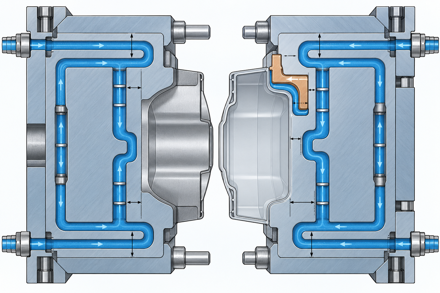
Mold Waterline Design: Make Mold Temperature on Both Sides Traceable
The temperature difference between the moving mold and the fixed mold directly causes greater shrinkage on one side and less shrinkage on the other, bending the part toward the side that cools more slowly. In waterline design, give priority to making the waterlines on the cavity and core sides as symmetrical as possible and at a consistent distance from the mold surface, and avoid overheating near the gate and overcooling far from the gate. Bubblers, baffles, and beryllium copper inserts can all improve local heat dissipation, but the premise is that the mold temperature control circuit itself can run stably. Nylon injection molded parts are more sensitive to mold temperature fluctuations than amorphous plastics; a mold temperature fluctuation of 5–10°C may already show a change in shrinkage rate.
Wall Thickness Differences and Gate Location: Structural Causes of Warpage
Where wall thickness changes abruptly, the thick region cools slowly and has more room to shrink, while the thin region sets first, creating internal stress at the junction. Controlling wall thickness differences within 25% during the DFM stage and using gradual transitions instead of steps is much easier than adjusting the machine later. Gate location is equally critical: pressure is high and orientation is strong near the gate, while shrinkage is greater at the far end away from the gate, making the part prone to a "banana shape." This is especially pronounced in glass fiber reinforced nylon, where the shrinkage rate difference between the flow direction and the perpendicular direction can reach several times; the gate should balance the flow as much as possible and avoid a long flow path on one side.
- Estimate cooling time based on the thickest wall first, and confirm that the thick region has sufficient rigidity before ejection.
- Keep the moving and fixed mold waterlines as symmetrical as possible, and control mold temperature fluctuations within a range that allows stable running.
- Control wall thickness differences within 25%, using gradual transitions rather than steps.
- For glass fiber reinforced materials, pay attention to flow orientation, and pursue flow balance in gate layout.
- Judge warpage by re-measuring 24 hours after demolding, not immediately upon ejection.
If the part has already set and dimensions can only be stabilized through post-processing or annealing, that means the criteria for the cooling stage were not established earlier. Only by treating cooling as a verifiable process variable rather than a passive step of "waiting for it to cool" can there be a foundation for dimensional consistency in nylon injection molding.
Mold Design and Venting: The Underlying Conditions for High-Precision Quality in Nylon Injection Molding
Gate Location and Runner Balance
The Relationship Between Venting and Burn Marks, Bubbles
Design points for mold temperature control circuits
Inspection and process control: how nylon injection quality is proven
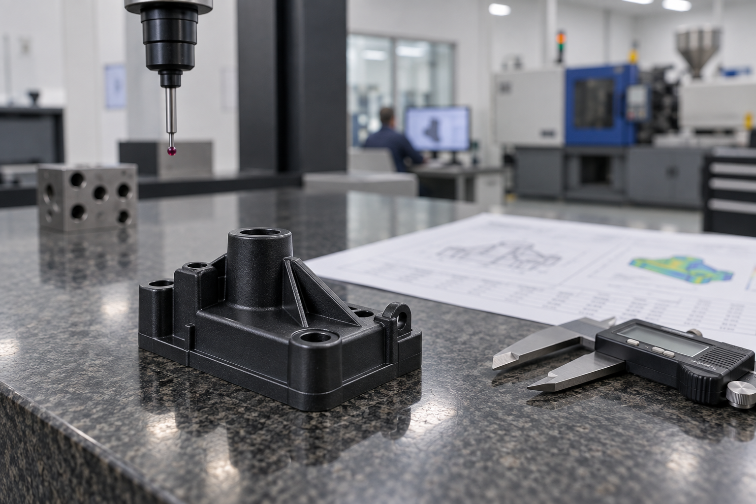
First article inspection: correlating process parameters with dimensions
- Key dimensions: prioritize mating dimensions marked on the drawing; full dimensional reports as needed.
- Warpage: flatness or datum plane deformation, measured with a CMM or a surface plate plus feeler gauge.
- Appearance: sink marks, flash, silver streaks, weld lines, judged against limit samples.
Process capability index: assessing the stability of nylon injection molding
Traceability: inspection results must be traceable back to parameters
Common defect quick reference: nylon injection defects—causes—countermeasures
The previous sections broke down the variables separately; what is truly useful on the shop floor is working backward from the phenomenon to the variables. The table below is arranged as "what you see—what to check first—how to adjust," suitable for reference during machine adjustment. The parameters in the table are common industry reference ranges; the specific values are subject to the drawing, material, and mold trial results.
| Defect phenomenon | Common causes | Priority countermeasures |
|---|---|---|
| Silver streaks, dull surface | Material not dried sufficiently, moisture content too high; melt temperature too high causing decomposition | Recheck drying temperature and time, seal the hopper; lower melt temperature, shorten residence time |
| Bubbles, internal voids | Moisture or gas not expelled; insufficient holding pressure; wall thickness too thick | Strengthen drying and venting; increase holding pressure and time; confirm wall thickness reduction with the designer |
| Sink marks, depressions | Holding pressure switchover too early; gate freezes too early; local wall thickness too large | Delay switchover point, increase holding pressure; enlarge gate or change gate position; optimize wall thickness transition |
| Flash, overflow | Injection speed too fast, pressure too high; insufficient clamping force; parting surface worn | Reduce speed and pressure and measure; verify clamping force; check parting surface and vent groove depth |
| Warpage, deformation | Uneven cooling; large temperature difference between the two sides; gate position causing uneven orientation | Balance the cooling channels to reduce mold temperature differences; adjust gate positions and quantity; extend cooling time |
| Dimensional out-of-tolerance, batch-to-batch variation | Mold temperature fluctuation; unstable packing pressure; changes in material moisture content | Lock down the mold temperature and packing pressure curves; retest moisture content for each batch; use first-article and in-process sampling to catch drift |
The row most easily overlooked in the table is "dimensional out-of-tolerance." It is often not a single cause, but the result of slight batch-to-batch drift in the two curves of mold temperature and packing pressure stacking on top of each other. So the recommended troubleshooting sequence on the floor should be fixed: first confirm the material's condition (dryness, moisture content), then confirm whether the mold temperature is stable, and only then touch the injection and packing parameters. If the order is reversed, it is easy to mess up a window that has already been tuned.
The value of a defect quick-reference is to shorten the time to locate the problem, not to replace systematic control. The same phenomenon may correspond to multiple causes. Move the variable with the lowest cost and smallest scope of impact first, change only one item at a time and record it, so that experience can be accumulated into a reusable process window.
Common Questions
The following questions all revolve around the criteria discussed earlier—high precision and high quality in nylon injection molding ultimately come down to drying, mold temperature, packing pressure, cooling, and inspection, not to saying "we do it very precisely."
The dimensions of nylon injection molded parts are always unstable. Which variables should be checked first?
Check in the order discussed earlier: moisture content, mold temperature, packing switchover point, and cooling uniformity. After nylon absorbs water, both melt viscosity and actual shrinkage change. If drying is insufficient, dimensions from the same set of parameters will drift. Mold temperature fluctuation causes inconsistent crystallinity, and shrinkage changes accordingly. If packing switchover is too early or too late, the density near the gate and at the far end differs, and dimensional repeatability cannot improve. It is recommended to first confirm the drying records and actual measured mold temperature, then adjust the packing curve. Do not change injection speed right away.
Is a higher or lower mold temperature more favorable for nylon injection molding precision?
There is no absolute answer; it depends on part wall thickness, flow length, and whether you want dimensional stability or appearance. With a higher mold temperature, crystallization is more complete, shrinkage is greater but more consistent from batch to batch, and surface gloss is better; with a lower mold temperature, cooling is faster and the cycle is shorter, but insufficient crystallization increases the risk of post-shrinkage and warpage. The common mold temperature range for PA6 and PA66 is around 80–100 °C, and glass fiber reinforced materials often need to go higher. The specific value should be based on the material supplier's recommendation and mold trial results. The key is that the mold temperature must be stable, not whether it is high or low in itself.
How should the packing curve for nylon injection molding be set to be considered reasonable?
First determine the packing switchover point, usually by injection pressure or position switchover, with switchover at about 95% cavity fill being common. After switchover, the packing pressure is generally 50%–70% of the injection pressure, then adjusted according to sink marks and dimensions. Packing time must cover gate freeze-off; packing after the gate freezes is meaningless and only lengthens the cycle. The judgment method is very direct: weigh the part. If the weight is stable, it means compensation is sufficient; if the weight is still increasing, it means packing time is insufficient. This logic is especially important for nylon because its shrinkage is greater than that of ordinary plastics.
For warpage in nylon injection molded parts, is it a cooling problem or a mold problem?
Most of the time it is both. Uneven cooling causes different shrinkage on the two sides of the part, and this is more obvious where wall thickness differs greatly; poor gate position and runner balance lead to inconsistent fill orientation, and warpage follows. The water channel design, mold temperature control circuits, and gate positions mentioned earlier all need to be looked at together. On the floor, you can first measure the mold temperature at different cavity positions to see how large the temperature difference is, then decide whether to modify the water channels or adjust the process. Warpage itself also needs a clear measurement datum; otherwise, whether it is warped or not cannot be stated clearly.
Can inspection catch high precision and high quality in nylon injection molding?
Inspection is proof, not remediation. First-article inspection, dimensional measurement, warpage, and process capability index monitoring can tell you whether the process is stable, but stability is determined by process parameters. The drying, mold temperature, packing pressure, and cooling emphasized earlier are what give the process capability; inspection confirms that this capability is still there. If Cpk is low, first go back to the process parameters to find the cause, rather than relying on 100% inspection to sort out parts. Traceability must also keep up: batches, drying records, mold temperature curves, and inspection data must match up so that problems can be located.
Key takeaways
- The number one source of nylon dimensional variation is moisture absorption: if the material is not dried, silver streaks, bubbles, and dimensional drift appear together.
- Mold temperature determines crystallinity and shrinkage rate—high mold temperature gives greater but stable shrinkage, low mold temperature tends to warp, and the two need a compromise.
- The packing switchover point, packing pressure, and packing time together determine sink marks and dimensional repeatability; looking at pressure alone is not enough.
- Uneven cooling causes shrinkage differences; cooling channel design is more effective than extending cooling time.
- First article inspection plus process capability monitoring is the only way to judge whether a batch is truly stable, rather than just looking at whether a single part passes.



