Why Breakthrough Burr Requirements Must Be Defined Separately for Cross-Hole Machining of Steel Parts
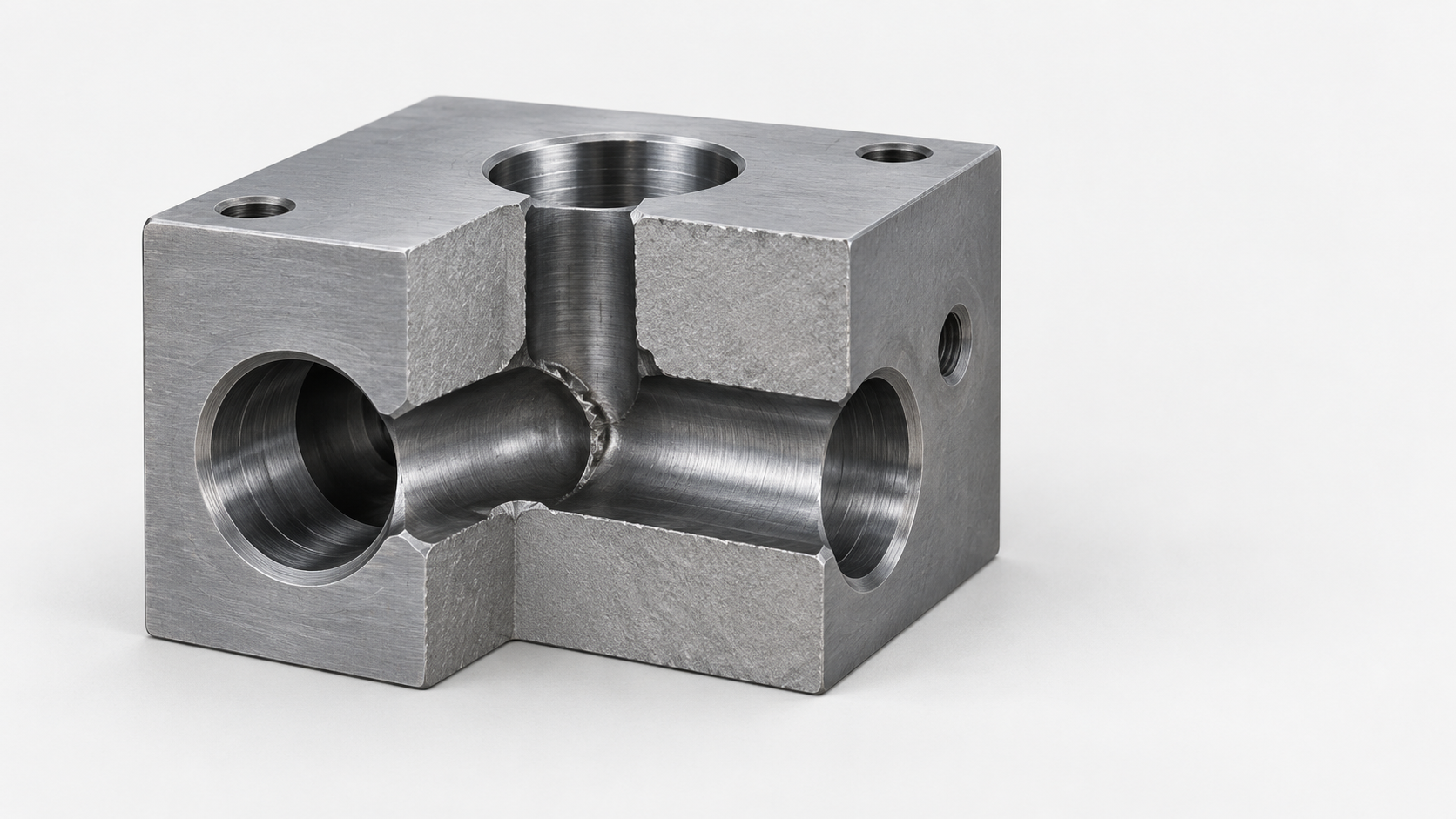
Consider a steel hydraulic valve body as an example: after a branch hole breaks into the main flow passage, a thin flared edge may remain at the intersection. During assembly, the seal passes over this edge and may be scratched; even when no abnormality is visible from the external hole opening, loose metal may still remain at the internal breakthrough. Cross-hole machining is not an ordinary hole-opening issue that can be solved by simply "adding another chamfer."
The risk depends on the part's function. Hydraulic valve bodies typically require attention to whether seals may be damaged and whether burrs narrow the flow passage; fuel passages are more sensitive to particle release, sharp edges, and the effects of rough surfaces on flow; pneumatic manifolds may involve leakage, cleanliness, and assembly insertion simultaneously. Different requirements correspond to different edge conditions and cannot all be summarized by the words "burr-free."
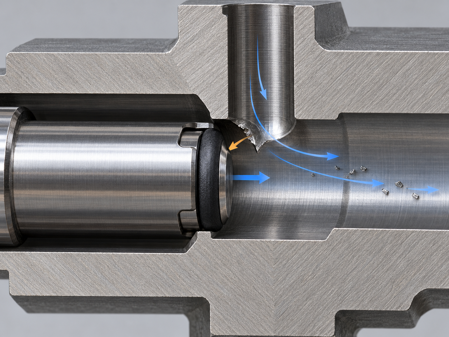
Therefore, drawings or purchasing requirements should separately specify the conditions that must not exist at the cross-hole intersection: sharp lips, loose particles, or attached burrs. They should also clearly state the permitted edge-breaking or radiusing condition and identify the hole diameter, sealing surfaces, threads, and flow-path areas that must not be damaged. If no numerical edge dimensions are specified, engineering and the supplier should define them jointly before machining, based on the cross-section, function, and inspection method, rather than relying on visual judgment afterward.
Before Cross-Hole Machining of Steel Parts, Identify Every Breakthrough Intersection
On the cross-section of a hydraulic valve body or steel cylinder body, where a main hole and a branch hole intersect, the intersection may retain a thin flared edge, torn edge, or loose metal. Even if the external hole opening has already been chamfered, the internal breakthrough intersection may still scratch seals, interfere with assembly, or carry particles into the flow passage. Therefore, cross-hole machining of steel parts should not focus only on whether the holes have been connected; it should first establish a process identification record for every intersection.
What Geometric Information Should Be Recorded for Cross-Hole Machining?
First distinguish the main hole from the branch hole, mark their diameters, orientations, depths, and intersection locations, and then check whether the wall thickness near the intersection is uniform. When the hole diameters differ substantially, the support conditions and flared-edge direction at the breakthrough may be different; locally thin walls are more prone to deformation or to forming a connecting lip that is difficult to break off. Also confirm whether the intersection is behind a thread, near a sealing surface, at the bottom of a blind hole, or in another structurally obstructed area, and determine whether the tool, deburring tool, borescope, or inspection gauge can reach it.
First, clearly document the functional risks of intersecting holes
For hydraulic valve bodies, the key concerns are seal scratches, leakage, and flow-passage cross-sectional area; pneumatic manifolds also require attention to flow resistance and residual particles; cylinder bodies with built-in seals must avoid scraping the seals against sharp edges during assembly insertion. Engineering reviews and procurement documents should list the critical hole diameters and depths, intersection locations, prohibited damage zones, acceptable edge deburring conditions, and cleanliness and functional inspection requirements. Only after these risks have been clearly defined can the subsequent hole machining sequence, breakthrough direction, and deburring method be arranged appropriately; a vague “burr-free” requirement cannot replace internal quality requirements for intersecting holes.
How to control intersecting-hole burrs through machining sequence and breakthrough location
Intersecting-hole machining should not focus only on “how to deburr at the end”; it is also necessary to first decide where the burr will be positioned. For the same group of holes, approaching from different directions can result in different locations and accessibility of the raised edge formed at the breakthrough. If the cross-section permits, the burr can be directed into a passage that is easier to access and clean later, rather than being hidden behind threads, near a sealing surface, or at the intersection of deep holes that cannot be inspected.
First compare the hole machining sequence and tool approach direction
Whether the main hole or branch hole should be machined first has no fixed answer that applies to all steel parts. Hole diameter, wall thickness, tool rigidity, and intersection function all affect the result. When the hole diameters, wall thickness, and tool conditions permit, machining the small hole first and the large hole afterward can sometimes push the intersection burr toward the side that is easier to process; however, if the small hole is a precision flow passage or a finished mating hole, subsequent machining may damage its wall, so this sequence cannot be applied mechanically.
During process reviews, mark every breakthrough intersection on the cross-sectional drawing and compare which drilling direction can reduce thin connecting lips, avoid sealing surfaces and threads, and preserve access for long-shank tools, borescopes, or cleaning media. The machining sequence should also be coordinated with finishing operations: rough machining that is prone to producing long chips should generally be completed first, while sealing surfaces, threads, and critical hole diameters should be machined at a stage when they will not be damaged again. The final solution must be verified by a trial cut to inspect the intersection geometry, rather than judged solely from the appearance of the hole openings.
Why feed should be adjusted in advance when the drill breaks through into an intersecting hole
When machining intersecting holes in steel parts, the drill tip approaches another passage and local support suddenly decreases. The cutting force originally supported by solid material may instead act on the thin wall or thin connecting lip around the intersection, causing flaring, tearing, or irregular chip breakage. If feed continues at the rate used during stable drilling, burr formation at the breakthrough is often more difficult to control. The purpose of adjusting the feed in advance is not to apply a fixed parameter, but to allow the tool to pass through the changing support area in a gentler and more controllable manner.
The feed strategy before intersecting-hole breakthrough must be confirmed by trial cutting
Within the limits permitted by tool diameter, intersecting-hole diameter, wall thickness, steel hardness, machine rigidity, and workholding conditions, the feed may be reduced before the anticipated breakthrough while monitoring cutting sound, load, chip formation, and exit condition. Gun drilling and deep-hole drilling likewise require attention to cutting forces and chip evacuation in the breakthrough area; the same cutting conditions should not be used throughout the entire hole depth simply because the passage is deep. The actual adjustment distance, feed value, and hold time must be determined through cross-sectional evaluation and trial cutting; experience from one steel grade or hole diameter cannot be copied directly to other parts.
Chip breaking, cooling, and exit condition also affect intersecting-hole quality
Feed adjustment can only reduce the risk at the moment of breakthrough; it cannot replace chip evacuation and cleaning control. If chips are too long, they may hang at the intersection, while cutting fluid may carry loose metal into the main hole, behind the threads, or into the sealing passage. After machining, check whether the exit has sharp lips, attached burrs, or loose particles, and confirm that subsequent deburring tools can reach the location. Compressed air can remove some loose chips, but it cannot prove that no attached burrs remain inside the intersecting hole; inspection must ultimately be arranged based on accessibility and functional requirements.
How to select a deburring method for steel intersecting holes: from manual methods to automation
For deburring steel intersecting holes, first determine whether the intersection is accessible, then consider production volume and consistency requirements. Shallow holes, exposed intersections, or simple low-volume parts can use controlled methods such as manual scrapers or rotary deburring tools. However, the operating direction, contact area, and applied force should be specified in the work instructions to prevent the scraper from enlarging the main or branch hole or damaging sealing edges, threads, or flow-passage cross-sections. After removal, perform magnified inspection to confirm that no sharp raised edges or loose metal remain.
Deep holes and concealed intersections: address accessibility first
When an intersecting hole is located at the bottom of a deep hole, behind threads, or inside a multi-passage structure, a manual tool may only be able to “touch” the intersection without reliably controlling the amount removed. In such cases, consider long-shank or flexible abrasives, dedicated intersecting-hole cutters, or mechanized processing using a CNC path. When selecting a method, confirm that the tool can enter the target area, and verify the edge condition using a cross-sectional test piece or first-article inspection; merely inserting a tool into the hole is not sufficient evidence that the internal burr has been removed.
High-volume machining of steel intersecting holes: focus on repeatability and residual material
For production batches, greater attention must be paid to the repeatability of every intersection. CNC-driven dedicated tools, robotic paths, or other automated methods generally make it easier to standardize the operation than complete reliance on manual work, but they must still be checked for excessive edge rounding, changes in hole diameter, or local enlargement of the flow passage. For micropores, multi-passage parts, or components sensitive to contamination risks, specialized methods such as abrasive flow machining, thermal deburring, and electrochemical deburring can be compared cautiously; none is universally optimal, and the steel grade, intersection dimensions, edge function, and abrasive or reaction residues must also be evaluated. Regardless of the method used, compressed air and cleaning are only subsequent steps and cannot replace internal edge inspection and cleanliness verification.
Quality inspection after intersecting-hole machining: internal edges, dimensions, cleanliness, and function
After machining intersecting holes in steel parts, acceptance cannot be concluded with the simple statement “deburring completed.” The intersections may be hidden inside deep holes, behind threads, or within internal flow passages. A neat-looking external hole entrance does not mean that there are no sharp raised edges, attached burrs, or loose metal inside. Inspection should include at least four separate aspects: internal edges, dimensional geometry, cleanliness, and function.
First confirm that the internal edges of the intersecting holes are safe
Visible intersections can be examined under magnification. For deeper or obstructed intersections, consider using a borescope, dedicated inspection gauge, or first-article sectioning. The focus is not to demand the complete absence of any slight rounding marks, but to confirm that there are no particles that could detach, sharp lips, or raised edges that could potentially scratch seals. For production batches, the sampling locations, magnification conditions, and recording method should also be specified; one apparently acceptable part does not automatically prove that the process is stable.
<p>The dimensions, cleanliness, and function must be verified separately</p>
Next, recheck the diameters and depths of the main and branch holes, as well as their intersection locations, and confirm that the threads, sealing surfaces, and flow-passage cross-sections have not been excessively scraped or rounded. Cleanliness is a separate requirement: compressed air can remove some loose chips, but it cannot prove that no attached burrs remain inside the intersecting holes. Verification should combine post-cleaning particle inspection or another agreed method. For hydraulic, pneumatic, and fuel passages, flow, leakage, or assembly checks may also be arranged according to risk, but the specific method should be determined by the functional requirements.
Therefore, drawings or purchasing documents should clearly specify the locations of the intersecting holes, critical hole diameters and depths, areas where damage is prohibited, the permitted edge-blunting condition, cleanliness requirements, inspection methods, and recording requirements, rather than merely stating “burr-free.” If the dimensional or edge condition has not yet been defined, engineering, purchasing, and the machining supplier should confirm it jointly before trial cutting.
FAQ: Common Questions About Machining and Acceptance of Intersecting Holes in Steel Parts
Acceptance of intersecting holes in steel parts should not be based solely on whether the external hole entrance appears neat. It should also consider the accessibility of the intersection, sealing or flow-passage function, internal edge condition, critical dimensions, and cleanliness, with inspection methods and record contents agreed in advance.
Can an external chamfer replace internal deburring of intersecting holes in steel parts?
Usually not. An external chamfer primarily treats the entrance edge and cannot ensure that thin raised edges, attached burrs, or loose particles are absent at the intersection of a deep or obstructed hole. For parts such as hydraulic valve bodies and cylinder bodies, the edge condition at the intersection should be specified separately, with internal deburring and inspection arranged according to accessibility.
Can compressed air prove that the inside of an intersecting hole is clean?
No. Compressed air helps remove some loose chips, but it may not remove burrs attached at the intersection and cannot replace cleanliness verification. Depending on the part risk, methods such as flushing, residual-particle inspection, borescope observation, or functional testing should be used in combination.
Does every steel part with intersecting holes require borescope or sectioning inspection?
Not necessarily. Visible, shallow, and lower-risk intersections can be inspected under magnification or with a dedicated inspection gauge. Deep holes, non-visible intersections, or critical areas involving sealing and flow may require a borescope, first-article sectioning, or other targeted verification. The method should be determined by the drawing requirements and failure risk.
Can machining the small hole first and the large hole afterward necessarily reduce burrs at the intersection?
Not necessarily. Under some combinations of hole diameter, wall thickness, and tooling conditions, this sequence may change the direction in which the burr falls, but it is not a universal rule. The machinist should also consider the hole's function, tool accessibility, threads, and sealing surfaces, and confirm the result through section evaluation or trial cutting.
If the drawing only states “burr-free” without numerical criteria, how should the purchaser conduct acceptance?
Before machining, the parties should jointly define an actionable edge condition—for example, no loose metal or sharp raised edges; which areas may be blunted or rounded; and which hole diameters, sealing surfaces, and flow passages must not be altered. The observation, dimensional, cleanliness, and functional inspection methods should also be specified. Do not treat “zero burrs” as a vague conclusion without an inspection basis.
Key takeaways
- The key risks in cross-holes are flared edges, chip breakage, and loose particles at hidden intersections; external chamfers cannot replace internal deburring.
- Hole diameter, orientation, depth, machining sequence, and tool accessibility should be coordinated during process design.
- Just before the drill breaks into another hole, the feed rate can be adjusted when permitted by the tool, wall thickness, and steel conditions; actual parameters must be confirmed through trial cutting.
- Deburring must remove sharp lips and loose metal while avoiding changes to the hole diameter, sealing surfaces, threads, and flow-path cross-section.
- Internal edges, dimensional geometry, cleanliness, and functional testing should be defined separately; compressed air or a single visual inspection cannot replace complete acceptance inspection.



