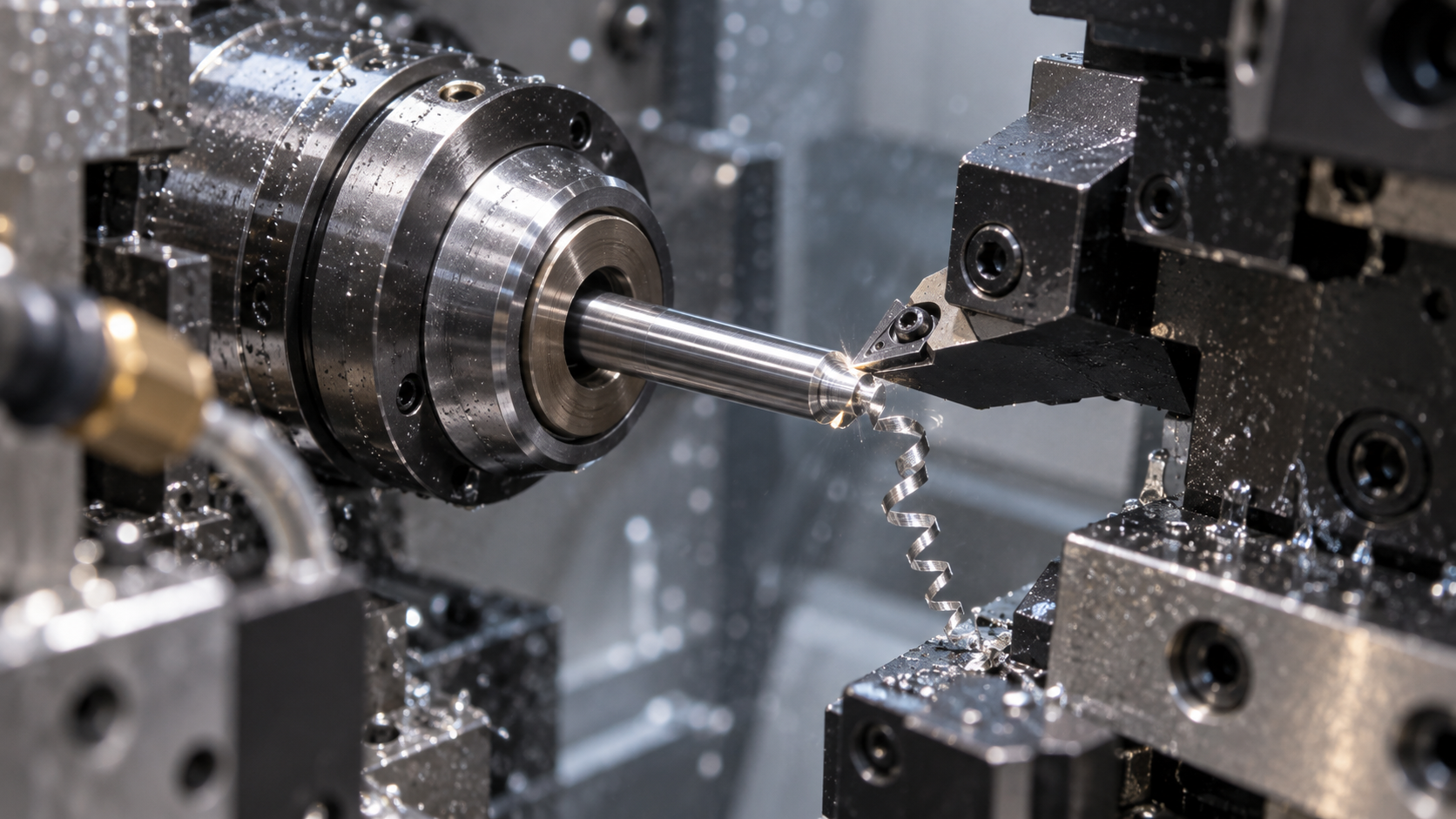
What Is Swiss-Type Machining: Explaining the Difference Between "Swiss" and "Sliding-Headstock" in One Sentence
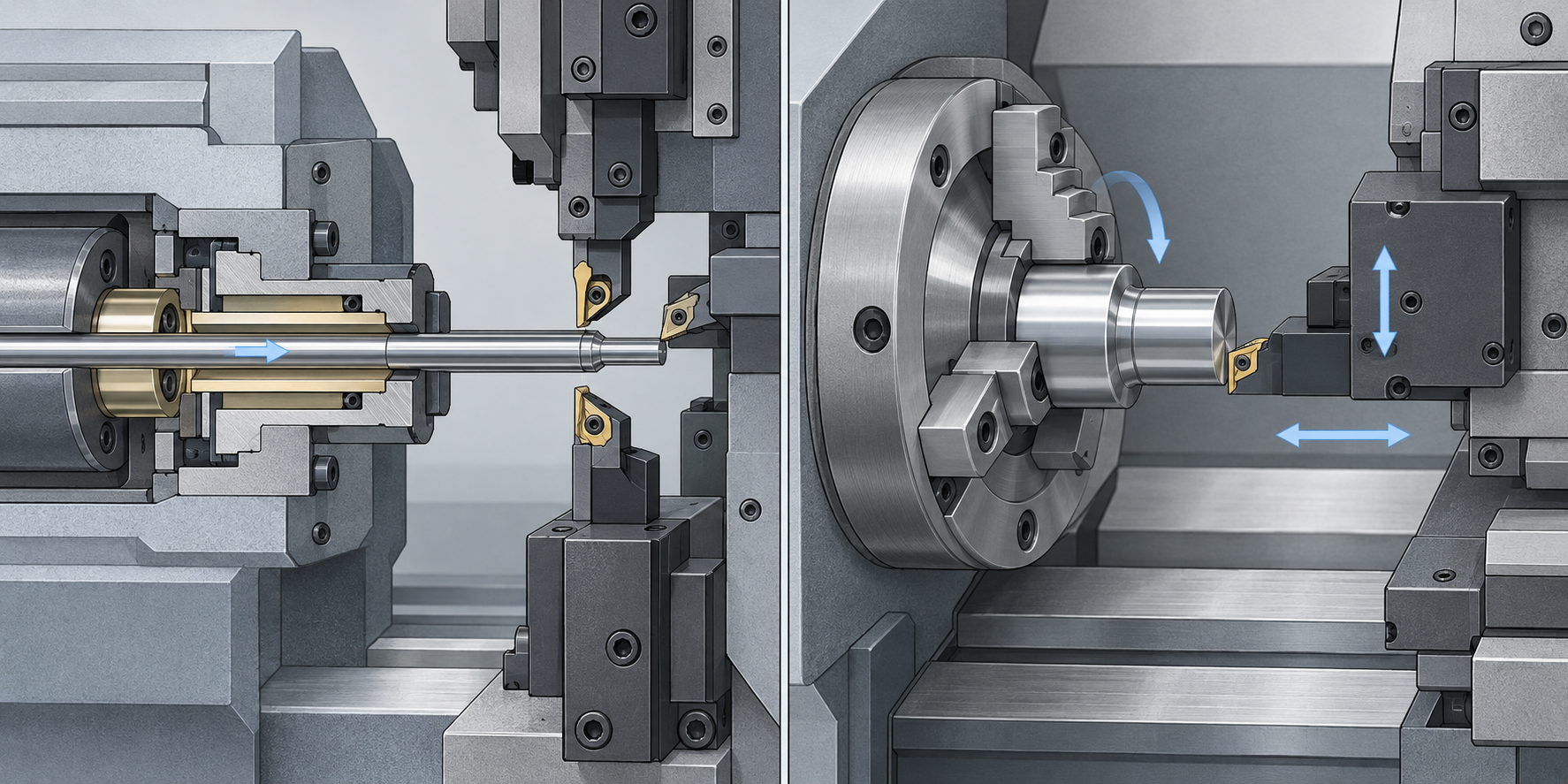
To understand what Swiss-type machining is, you don't actually need to memorize its history first. One sentence is enough: A Swiss-type machine has the material moving while the tool stays essentially still; an ordinary lathe (sliding-headstock machine) has the material rotating in place while the tool moves. This difference determines all the advantages, shortcomings, and scope of application that follow.
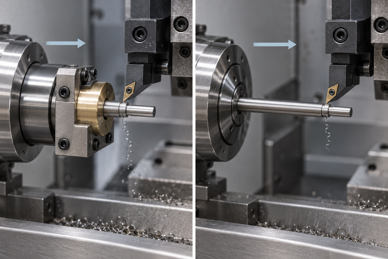
The full name of a Swiss-type machine is Swiss-type CNC lathe, often called a Swiss-type automatic lathe or CNC Swiss machine in English. Its main spindle grips a long bar stock and feeds it axially along the Z axis—this is the origin of the words "Swiss-type": the bar stock is pushed forward all the way into the cutting zone. The tools are mounted on the X and Y tool rows and the live tool turret, and are responsible for cutting. A sliding-headstock machine (what we usually call an ordinary CNC lathe) is exactly the opposite: the workpiece is gripped by the chuck and rotates in place, while the tool moves along X and Z to cut it.
| Comparison Item | Swiss-Type Machine (Swiss Type) | Sliding-Headstock Machine (Ordinary CNC Lathe) |
|---|---|---|
| Material State | Gripped bar stock feeds axially along the Z axis | Chuck grips and rotates in place |
| Tool status | Cutting in the X/Y directions, with essentially no axial travel | Cutting while moving along X/Z |
| Support method | The guide bushing supports the bar stock closely against the cutting point | The overhanging portion has no close-fitting support |
| Parts it excels at | Micro-miniature, slender shaft-type, small-batch small parts | Discs and sleeves, short and stubby parts, large-diameter parts |
| Typical diameter | Common industry upper limit on the order of about 20–38 mm | Larger diameters achievable depending on the machine model |
Why did this "material moves" structure evolve? Because it was inherently designed for micro-miniature, slender shaft-type parts. The machining diameter upper limit of a Swiss-type lathe is commonly on the order of 20–38 mm in the industry, varying greatly by machine model; for micromachining, the diameter can be as small as on the order of 1 mm. In other words, the main battlefield of the Swiss-type lathe is not "large parts," but those small things that on an ordinary lathe are easily bent by cutting forces, chatter, and turn out non-round—connector pins, camera decorative rings, watch movement shafts, and medical probes are all regulars for it.
So when someone asks "what is Swiss-type machining," the most practical answer is not to recite a definition, but to remember this picture: a slender metal bar stock, pushed by the spindle through a close-fitting small sleeve, with the tool cutting right at the sleeve's exit—the material is moving, and the tool is almost standing still. Once you understand this picture, concepts like the guide bushing, remnant material, and dual spindles all have somewhere to land. In the following sections, we will break things down along this picture.
The working principle of Swiss-type machining: why the guide bushing is the soul
Where the guide bushing is located, and what exactly it is supporting
The main spindle feeds along the axial direction, and the tool is only responsible for cutting—this division of labor is crucial
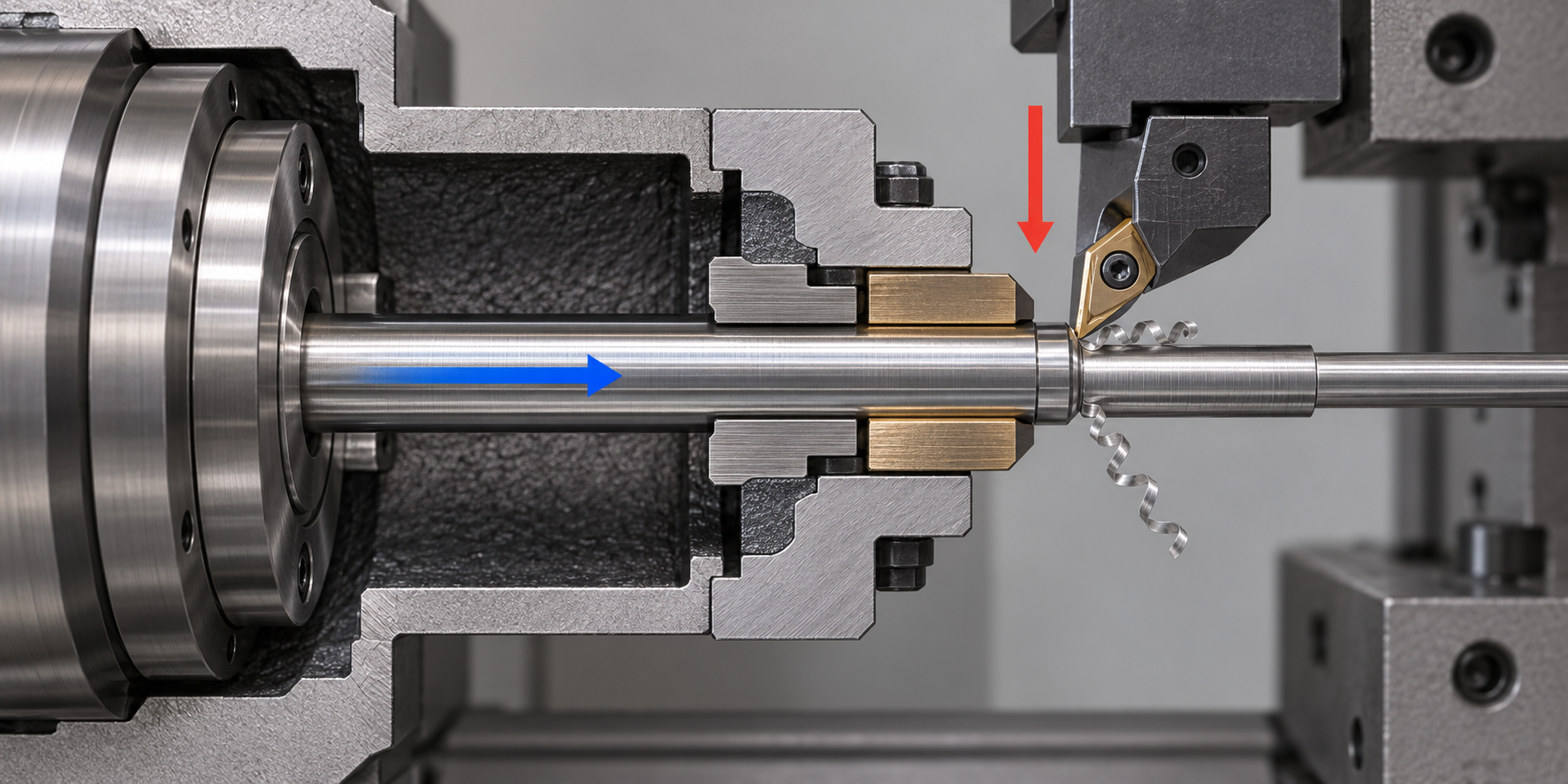
If the stock itself is not straight, the guide bushing cannot save it
How Swiss-type machining is done: from feeding and the guide bushing to completing both ends in one setup
Earlier we discussed "the material moves while the tool basically does not" and guide bushing support. When these two things are applied to actual machining, they form a very smooth process: the bar feeder pushes the long bar stock into the main spindle, the stock passes through the guide bushing, the main spindle grips the stock and performs axial feed, and the tool cuts near the guide bushing; when milling, drilling, tapping, or slotting is needed, powered tools come into play; after one end of the part is completed, the sub-spindle takes over to machine the other end, all without releasing the clamp. So the answer to the question "How is Swiss-type machining done?" is essentially this process plus the result of "completing both ends in one setup."
Step 1: Feeding and passing through the guide bushing, turning long bar stock into a machinable stock end
The bar stock is first pushed in along the main spindle axis by the bar feeder, with its front end passing through the guide bushing and exposing a short section—this section is what will be cut off next. The inner diameter of the guide bushing and the outer diameter of the bar stock are in a fit relationship with very small clearance. In the industry, guide bushings are commonly matched by stock diameter grades, so changing the stock diameter on the same Swiss-type machine often requires changing the guide bushing. This step also explains why Swiss-type machines have high requirements for the bar stock itself: if the stock's straightness and ovality are not up to standard, it will bind when passing through the guide bushing, and the guide bushing will not be able to support it during cutting—if the stock itself is not straight, the guide bushing cannot save it. The end of the bar stock generally also needs chamfering or necking to facilitate passage through the guide bushing, which is also part of the preparation process.
Step 2: Main spindle feed, turning the outer diameter, grooving, and thread turning
The main spindle grips the bar stock and performs axial feed forward along the Z axis, while the tool cuts in along the X/Y directions. Because the cutting point is always tight against the guide bushing, this section can be turned very thin and very long without deflection or vibration. Conventional turning operations such as outer diameter turning, grooving, thread turning, and chamfering are completed here. A common industry practice is to mount multiple tools on a tool row or turret and feed them in program sequence; the cycle time for simple small parts can reach the order of about 10 seconds—of course, this depends on part complexity and material, and not all parts are this fast. This is also the stage where the precision of Swiss-type machining is most easily demonstrated: dimensional consistency relies on guide bushing support plus stable feed, not on the operator's feel.
Step 3: Powered tools perform flat milling, drilling, tapping, and slotting
If the side of the part needs flat milling, the end face needs drilling, the hole needs tapping, or the outer diameter needs slotting, the main spindle can stop or perform indexing positioning, and the powered tool (with its own rotational power) cuts in from the side or end face. This step is the key to a Swiss-type machine changing from a "lathe" into a "turn-mill compound." A common industry configuration is multiple powered tool positions, capable of chaining turning, milling, drilling, tapping, and boring together on one machine; the effect of process convergence is here—features that originally required secondary clamping on a milling machine are now completed on the same machine in the same setup.
Step 4: The sub-spindle takes over the part and completes both ends in one setup
The main spindle finishes one end of the part, then the sub-spindle (also called the counter-spindle in the industry) comes over to grip the part, the main spindle releases its grip and retracts, and the sub-spindle takes the part away to machine the end that was originally clamped. The value of this step lies in: the related features on both ends are produced under the same clamping datum. The coaxiality of the two ends, and the perpendicularity of the end face to the axis, will not introduce new positioning errors due to "turning the part around for a second clamping"—during a second clamping the part is re-aligned, and once the datum changes, coaxiality easily goes out of tolerance. Swiss-type machining bypasses this problem in principle, and this is its most solid advantage when making slender shaft-type parts and small parts with features on both ends.
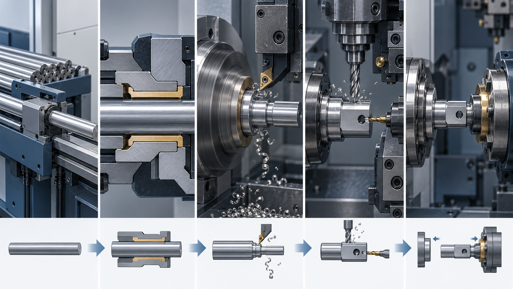
Looking at the four steps together, the answer to "how" Swiss-type machining is done is not the technique of any single operation, but the process design itself: feeding—passing through the guide bushing—main spindle turning—live tooling combined machining—sub-spindle receiving the part to machine the other end, all without releasing the grip throughout. Converged operations, fewer transfers, and small cumulative error are the natural results of this process, not something recovered through extra inspection. Whether a specific part can be arranged this way still needs to be evaluated together with the drawing, batch size, material, and equipment—Swiss-type machining is not cost-effective for all parts.
Guide bushing or no guide bushing: a real trade-off in Swiss-type machining
When talking about Swiss-type machining, one question is unavoidable: does this machine have a guide bushing or not? Many people treat it as the difference between "high configuration and low configuration," but it is not. It is more like choosing shoes—wear running shoes for a marathon, wear flip-flops at the beach; neither is more advanced, only more suitable. Whether there is a guide bushing (guide sleeve) determines what this Swiss-type machine is good at and not good at, and directly determines your material costs and whether your part can be machined.
Let's put the conclusion up front: with a guide bushing, rigidity is good and precision is stable, but the remnant is long; without a guide bushing, material is saved and the remnant is short, but it is picky about bar stock and part shape. Let's break it down below.
With guide bushing: good rigidity, at the cost of remnant
In a Swiss-type machine with a guide bushing, the bar stock passes through the guide bushing and is then clamped by the main spindle, with the guide bushing supporting the material right at the cutting point. As soon as the cutting force is applied to the stock, the guide bushing "holds it up," so slender stock is not easy to bend or vibrate. Therefore, slender shafts, hard materials, and parts with high precision requirements basically all take the guide bushing route.
But the guide bushing itself occupies a length. When the spindle stroke is finished, there is always a section of stock inside the guide bushing that cannot be pushed out, and this section is the remnant. In the industry, the remnant of Swiss-type machines with a guide bushing is commonly on the order of 120–180 mm, with considerable variation between models. If a bar is 3 meters and the remnant is 150 mm, it does not look like much; but if the material is expensive—such as titanium alloy or certain medical stainless steels—throwing away a section from every bar adds up to real money at large batch sizes. Moreover, the remnant cannot be completely eliminated, only shortened or recycled as much as possible, and this must be factored into cost in advance.
Without guide bushing: saves material, but is picky about stock and jobs
In a Swiss-type machine without a guide bushing, the guide bushing is eliminated, and the bar stock is fed directly while clamped by the spindle. The most direct benefit is a short remnant—on some models the remnant can be reduced to a few dozen millimeters or even shorter, and material utilization rises noticeably. For materials that are relatively easy to cut and cheap, such as copper and aluminum, or when the batch size is large enough that material cost dominates, this advantage is very real.
The cost is that rigidity is not as good as with a guide bushing. Without a guide bushing supporting right at the cutting point, the overhanging portion of the bar stock relies entirely on the spindle and its own rigidity. Therefore, without a guide bushing, the requirements for the bar stock's straightness and ovality are higher—if the stock itself is not straight, the cut will be off; there are also limits on the part's length-to-diameter ratio, and if it is too slender and too long it easily causes chatter; hard materials and high-precision parts also tend to suffer. In addition, on machines without a guide bushing, the spindle and bearings bear the cutting force more directly, which affects service life when doing heavy work over the long term, and this is also a point to ask about clearly when selecting a machine.
How to choose: after asking four questions, you have the answer
No need to memorize parameters; ask yourself four questions and you can set the direction:
- Is the material expensive? For titanium alloys, superalloys, and precious metals, every remnant hurts, so prioritize considering no guide bushing or find ways to shorten the remnant; for ordinary carbon steel and brass, the remnant has little impact, and a guide bushing is more stable.
- Is the batch size large? For small batches, the remnant and setup are spread over each piece at a high proportion, so calculate clearly; for large batches, the remnant is diluted, but the rigidity advantage of a guide bushing is also easier to realize.
- How large is the part's length-to-diameter ratio? For shafts with a large length-to-diameter ratio that are slender and long, a guide bushing is almost essential; for short, thick parts and disc-sleeve types with a small length-to-diameter ratio, no guide bushing is entirely sufficient.
- How tight is the precision requirement? If it needs to hold steady at the micron level with strict surface roughness requirements, the rigid support of a guide bushing makes it easier to maintain; for general precision and simple shapes, no guide bushing is more economical.
There is no standard answer here. The same drawing, with a different shop, a different batch of material, or a different batch size, may lead to a different choice. So don't just ask "do you use a guide bushing or not," a more effective question is: "For this part of mine, this material, this batch size, which is more suitable, and how do you evaluate the remnant and precision?" — putting the trade-offs on the table is far more reliable than hearing "we can do both."
One final reminder: with a guide bushing and without a guide bushing are not an upgrade relationship, they are two different capability paths. The core value of Swiss-type machining lies in making micro-sized, slender shaft-type parts accurately and stably; which guide bushing configuration to choose is an engineering judgment made around this goal, not a contest of who is more "advanced." For your specific part, the final decision still needs to be evaluated together with the drawing, batch size, material, and equipment.
What parts are suitable for Swiss-type machining, and what parts are not
When it comes to Swiss-type machining, many people instinctively feel that "precision parts should go on a Swiss-type machine." This judgment is only half right. A Swiss-type machine is not a more advanced lathe; it is a tool grown specifically for a certain class of parts. Only by understanding its strengths and weaknesses will you not go astray in selection.
Parts suitable for Swiss-type machining: small, slender, long, with features on both ends
The comfort zone of Swiss-type machining can be framed by four characteristics: small diameter, large length-to-diameter ratio, features on both ends, and scale batch size. The support of the guide bushing greatly increases the rigidity of slender shaft-type parts, and the sub-spindle means the holes, slots, and threads on the other end do not need a second setup. These two capabilities combined determine that the following part types are especially well matched.
- Connector pins and terminals: diameters are often at the millimeter level, with large length-to-diameter ratios, and the two ends may have chamfers, steps, and crimp zones, with batches often in the tens of thousands. Swiss-type machines feed, turn, and cut off in one smooth sequence, and the cycle time can be kept very short.
- Camera decorative rings, micro shafts, small hinge parts: small in shape but requiring coaxiality and end-face precision, and metal appearance parts also need good surface roughness. Powered tools can directly mill flats and drill holes, reducing process transfers.
- Watch movement shafts, medical probe-type parts: slender, long, and requiring high precision, the material may be stainless steel or titanium alloy. Swiss-type machines with a guide bushing have a clear advantage when machining such parts.
- Batch small parts that need turning, milling, drilling, and tapping completed in one go: for parts with features on both ends where multiple setups would accumulate errors, the sub-spindle is most valuable.
Parts not suitable for Swiss-type machining: short and stubby, large diameter, too small a batch
Conversely, forcing the following types of parts onto a Swiss-type machine often yields poor results or is even uneconomical.
- Short, stubby single pieces: the part length is very short and the length-to-diameter ratio is very small, so the guide bushing advantage of a Swiss-type machine cannot be brought into play, while you still bear the remnant loss and setup time. In this case, an ordinary CNC lathe is more direct.
- Large-diameter parts: the common maximum machining diameter in the Swiss-type machine industry is on the order of about 20–38 mm, with large differences between models. Parts exceeding the machine's upper limit simply cannot fit, and this needs to be confirmed according to the specific equipment.
- Disc-and-sleeve parts and flange parts with very small length-to-diameter ratios: for such parts, a sliding-headstock machine (material rotates, tool moves) often has better rigidity and chip evacuation conditions, while a Swiss-type machine is instead awkward.
- Parts with too small a batch size: the efficiency advantage of a Swiss-type machine is built on batch size. If the batch is too small, the setup time and the longer remnant of guide-bushing models (commonly on the order of about 120–180 mm in the industry) cannot be amortized, and the per-piece cost may be higher than an ordinary lathe.
One point must be emphasized here: not suitable does not mean "cannot be done," but rather "not cost-effective." Swiss-type machines can turn a very wide range of part types, but their original design intent is efficient batch machining of micro-sized slender parts; deviate from this scenario, and the advantages are offset.
One actionable judgment: with a drawing in hand, look at four numbers first
If you have a drawing in hand and are not sure whether it should go on a Swiss-type machine, go through it in this order:
Once you've gone through the four steps, you'll basically have a direction on whether Swiss-type machining is a good fit. Of course, the final judgment also depends on the material's machinability, tolerance requirements, and surface quality—these are covered in the next section.
Common Materials and Typical Application Scenarios for Swiss-Type Machining
The parts list for Swiss-type machining is essentially a list filtered by size. Not too large in diameter, slender, produced in batches, with features on both ends—parts that meet these criteria can mostly be completed in one setup on a Swiss-type machine. The material determines another thing: whether the bar stock can stably pass through the guide bushing and be cut while being held tightly.
Which materials commonly go on Swiss-type machines: first look at machinability, then whether they can pass through the guide bushing
On a Swiss-type machine, the bar stock is clamped and fed axially through the guide bushing, so the material's own "regularity" and "machinability" directly determine how smoothly machining goes. Common choices in the industry fall roughly into several categories:
- Free-cutting steel (such as 12L14 type): the most common entry-level material, with good chip breaking and easy surface quality, suitable for high-volume pins and shaft-type parts.
- Stainless steel (303, 304, 316 types): 303 is a regular on Swiss-type machines, with relatively friendly machinability; 304/316 are stickier and prone to work hardening, placing higher demands on tooling, spindle speed, and cooling, and on slender parts you especially need to watch for tool deflection and vibration.
- Brass, copper alloys: good machinability, often used for connectors, terminals, and small shafts, with cycle times that can be kept very short.
- Aluminum alloys: light and easy to cut, suitable for camera rings and small structural parts, but the material is soft and slender parts are easily clamped and deformed.
- Small titanium alloy parts: poor machinability, low thermal conductivity, and fast tool wear; here the rigidity and single-setup capability of a Swiss-type machine are actually advantages, but both material cost and tooling cost must be factored in beforehand.
One often overlooked point: material machinability affects whether a guide bushing can be used. Materials with high cutting forces and a tendency to work harden are actually more stable on machines with a guide bushing; while materials that are too soft and sticky are prone to galling or chip clogging inside the guide bushing. So material selection is not isolated—it must be considered together with the guide bushing, tooling, and cooling.
Typical application scenarios for Swiss-type machining: from medical probes to camera rings
The main battlefield for Swiss-type machining is those parts that are "small, slender, batch-produced, with work on both ends." Common application scenarios are concentrated in several industries:
- Medical devices: probe rods, small shafts related to endoscopes, and slender parts on surgical instruments, with high requirements for surface quality and coaxiality; completing both ends in one setup is a must.
- Electronic connectors and pins: diameters often in the 1–5 mm range, high volume, short cycle times; brass and free-cutting stainless steel are common materials.
- Consumer electronics: phone camera decorative rings, small hinge and pivot parts, slender shafts on wearable devices—small in size, but end faces, steps, and chamfers cannot be sloppy.
- Watches and precision instruments: mandrels and gear shaft-type parts with large length-to-diameter ratios, which are exactly the strength of Swiss-type machines.
- Small aerospace parts: some small fasteners and sensor parts, with materials that are harder to cut, but batch sizes are not necessarily large; whether to use a Swiss-type machine depends on whether the batch size can amortize the setup cost.
These scenarios share one thing in common: if the part were moved to an ordinary lathe, it would either be impossible to clamp, or it would bend when clamped, or both ends would require two separate setups and coaxiality could not be maintained. Swiss-type machining solves exactly these kinds of problems.
Tolerances and cycle times: common magnitudes in the industry, but they must be evaluated based on actual conditions
When it comes to the capabilities of Swiss-type machining, two numbers are often mentioned: tolerances can reach the micron (μm) level, and cycle times for simple small parts can be seen at around 10 seconds. These two numbers are indeed common in the industry, but they are order-of-magnitude indicators, not promises.
Whether tolerances can reach the micron level depends on part geometry, material, tool condition, and the machine's own precision and thermal stability; on the same machine, cutting a brass pin versus cutting a thin titanium alloy shaft will produce very different results. The same goes for cycle time: a pin with only an outer diameter and a chamfer might take a few seconds per piece; once you add milling flats, drilling, tapping, and sub-spindle backworking, the cycle time can multiply. If a drawing says "precision" and you assume a Swiss-type machine will definitely meet it, that is a common misjudgment. Whether a specific part can meet the tolerance and cycle time needs to be evaluated together with the drawing, material, batch size, and equipment.
Beyond materials and applications, don't forget surfaces and post-processing
Parts coming off a Swiss-type machine usually have fairly controllable surface roughness, because cutting is stable and vibration is low under guide bushing support. But the material itself sets an upper limit: for stainless steel 304 to achieve a mirror-level surface, subsequent polishing or grinding is often still needed; aluminum alloy tends to show tool marks and burrs, so deburring operations need to be scheduled in advance.
In addition, Swiss-type machining is often combined with other processes: in the small-batch trial stage, CNC machining or 3D printing can be used to validate the structure first, and after confirmation, Swiss-type machining can be used for volume production; when plastic parts are needed in volume, consider injection molding. The specific material grades, machinability, and available bar stock specifications can be checked against the materials library, which is far more reliable than choosing materials by feel.
How to judge whether a part needs Swiss-type machining: a practical path for buyers and engineers
Common questions about Swiss-type machining
The following questions are basically the ones most likely to come up after reading the previous content: where exactly does the precision come from, how to choose between guide bushing and no guide bushing, whether remnant material can be saved, what the diameter limit is, and whether small batches are worth running on a Swiss-type machine. The answers are given according to engineering reality, without promises.
Is Swiss-type machining always more precise than a sliding-head machine (ordinary CNC lathe)?
It cannot be generalized, but in direction, Swiss-type machines are more likely to maintain precision on slender shaft parts. The reason is that the guide bushing supports the bar stock close to the cutting point, and the point where the cutting force acts is very close to the support, so slender stock is less likely to deflect and vibrate. Conversely, if the part is a short, thick disc or sleeve with a very small length-to-diameter ratio, the sliding-head machine's clamping rigidity is already sufficient, and the Swiss-type machine may not have an advantage, while also bearing extra remnant material and setup costs. So the basis for judgment is the part shape and length-to-diameter ratio, not the word "Swiss-type" itself. In the industry, Swiss-type machines commonly achieve dimensional tolerances at the micron (μm) level stably, but for a specific part and a specific material, it still must be confirmed by drawing and actual equipment measurement.
How exactly should you choose between guide bushing and no guide bushing?
Treat it as a trade-off problem: with a guide bushing, rigidity is good, suitable for slender shafts, hard materials, and parts with higher precision requirements, at the cost of longer remnant material, commonly around 120–180 mm in the industry; without a guide bushing, remnant material is shorter and material is saved, suitable for bar stock with a not-too-large length-to-diameter ratio, not-too-high hardness, and shorter length, but the burden on the spindle and bearings is heavier. In actual selection, first look at whether the material is expensive, whether the batch is large, and how large the part's length-to-diameter ratio is, then look at precision requirements. Neither is more advanced; only one is more suitable. The final decision should be based on the equipment manufacturer's model parameters and actual trial cutting.
Can remnant material in Swiss-type machining be completely avoided?
It is very difficult to avoid completely. Guide bushing models naturally have longer remnant material because the guide bushing itself occupies a certain length; no-guide-bushing models have shorter remnant material, but it is not zero either. Remnant material is essentially the safety margin left by the clamping and feeding mechanism; it can be reduced, but not eliminated. For precious metals or large batches, the proportion of remnant material directly affects cost, so quotations and process evaluations usually need to include remnant material in the calculation. How much it can be reduced depends on the machine model, bar diameter, and feeding method, and needs to be confirmed according to the actual equipment and part.
What is the maximum diameter of parts that Swiss-type machining can handle?
The main battlefield of sliding headstock machines is micro and small parts. The industry-common maximum machining diameter is on the order of about 20–38 mm, with large differences between machine models; in the micromachining direction, it can reach the 1 mm order of magnitude. For parts exceeding a machine model's upper limit, you generally need to switch to a turret lathe or a turn-mill center. So the first step when receiving a drawing is to check whether the maximum outer diameter falls within the target machine model's range, and only then discuss the length-to-diameter ratio and batch size. The specific upper limit is subject to the equipment specification sheet; do not assume that just because "sliding headstock machines are very precise," they can make any size.
The batch is very small—is it worth using a sliding headstock machine?
It depends on how small. The advantage of sliding headstock machines lies in batch, continuous production: bar feeding, completing both ends in one clamping, and fast cycle times; for simple small parts, cycle times on the order of about 10 seconds are seen in the industry. However, fixed costs such as setup, programming, and remnant material spread over very few pieces will make the per-piece cost noticeably high. If it is just a few pieces, or a dozen or so short-bar single pieces, an ordinary CNC lathe or turn-mill is often more cost-effective. The way to judge is simple: estimate the batch size, material unit price, remnant length, and setup time together, then decide whether to use a sliding headstock machine. In the end, an actual evaluation still needs to be made based on the drawing and batch size.
Key takeaways
- In Swiss-type machining, "Swiss" means the main spindle holds the bar stock and feeds it along the axial direction, while the tool stays essentially still; in a sliding-headstock machine, by contrast, the material rotates and the tool moves to cut it.
- The guide bushing (guide sleeve) supports the bar stock right at the cutting point, which is the direct reason slender shafts resist bending and vibration and can maintain relatively high precision.
- Dual spindles plus live tooling allow a part to be turned, milled, drilled, tapped, and slotted on a single machine; after the sub-spindle takes over, secondary clamping errors are reduced.
- Having a guide bushing gives good rigidity but leaves a longer remnant; not having one saves material but is limited by the length-to-diameter ratio and material hardness—this is a trade-off, not a relationship of upgrade.
- Swiss-type machines excel at micro, small, slender, and batch-produced small shaft parts; short single pieces, large diameters, and parts with a low length-to-diameter ratio are usually not their strong suit.



