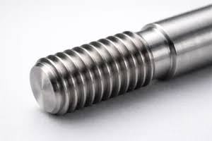
What Thread Machining Methods Are Available? First Distinguish Cutting from Forming
There is no “best answer” for thread machining methods independent of the application conditions. Before selecting a process, first confirm whether the thread is an internal or external thread, then verify the thread profile, pitch, hand, number of starts, and thread tolerance. Next, determine whether the part rotates about its center, whether the material produces short chips, whether the structure is thin-walled or has a long overhang, and whether the clamping, chip evacuation, and machine-tool capabilities are compatible.
From the standpoint of machining principles, common methods can be divided into two groups. Turning, milling, tapping, die threading, grinding, and whirling milling are classified as cutting processes, which form the thread profile by removing material with a cutting tool or abrasive tool; thread rolling and extrusion are classified as plastic forming, which deform the blank using rollers or dies. Tapping is generally used for internal threaded holes, while die threading is generally used for external threads. However, external threads can also be produced by turning, milling, and other processes.
| Method | Typical Applications | Key Advantages | Key Limitations |
|---|---|---|---|
| Thread Turning | Rotating shafts and sleeve-type parts | Broad applicability across thread profiles | Requires stable rotation and synchronized feed |
| Thread milling | Non-rotating parts, thin-walled parts, and large-diameter threads | Lower cutting forces, making chip breaking easier | Relies on milling equipment and programming |
| Tapping / die threading | Internal threaded holes / external threads | A straightforward process, commonly used for standard sizes | Requires control of torque, chip evacuation, and chip jamming |
| Rolling / extrusion | Batch-produced parts suitable for plastic forming | The thread profile is formed without removing material | Limited by the material, blank, and equipment |
| Grinding / thread whirling | Finishing parts / slender screws | Suitable for special finishing or slender-part applications | Requires dedicated equipment and process conditions |
Therefore, answering “What thread machining methods are available?” is only the starting point. A sound process decision must compare the thread characteristics, part geometry, material, production volume, and inspection requirements together: turning can be evaluated first for rotational shaft-type parts, milling can be considered for non-rotating or thin-walled structures, tapping can be considered for common internal threaded holes, while rolling and extrusion require confirmation that the material’s plasticity and the forming equipment are suitable.
Thread turning: a common thread machining method for rotational workpieces
Thread turning is a thread machining method based on workpiece rotation. After shafts, sleeves, flanges, and other rotational parts are clamped on a lathe, the workpiece rotates around the spindle center while the tool remains synchronized with the spindle speed according to the pitch and gradually feeds in the axial direction to cut the specified thread profile. By changing the tool and adjusting the feed and cutting path, operators can typically machine both external and internal threads, as well as threads with different profiles.
Applicable Scenarios for Thread Turning
When a part can be positioned stably around the rotational center and the thread axis is aligned with the spindle direction, thread turning is generally relatively easy to plan. It is suitable for single-piece or small-batch rotational parts and makes it convenient to adjust the pitch, hand, number of starts, and thread profile according to the drawing. When machining internal threads, the internal hole diameter, hole depth, and the space available for tool entry and exit must also be confirmed; for external threads, check that the end has a sufficient relief groove or a safe tool-retraction position.
Workholding and Limitations of Thread Turning
The results of thread turning depend not only on the tool but also on workholding rigidity, spindle synchronization, the material's chip-breaking characteristics, tool-tip condition, and cutting parameters. Parts with long overhangs or thin walls are prone to vibration and deformation under cutting forces; deep-hole internal threads may present difficulties with chip evacuation and cooling. For such structures, the clamping method, tool overhang, relief groove, and machining sequence should be reassessed. The final process must still be confirmed based on thread tolerances, surface requirements, and the use of thread gauges or other inspection methods; fixed accuracy cannot be inferred solely from the method name "turning."
Thread Milling: The Choice for Thin-Walled, Long-Overhang, and Non-Rotating Parts
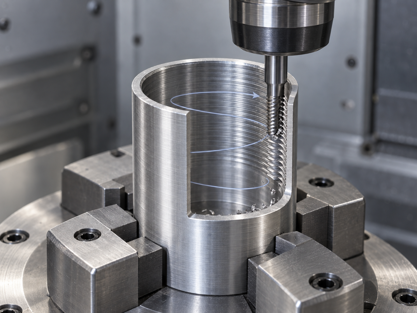
Thread milling gradually forms the thread profile through the helical interpolation motion of a milling cutter. The tool moves circumferentially while feeding axially at the thread pitch, allowing it to machine both internal and external threads. The workpiece does not need to rotate around its own center, making this process suitable for non-rotating parts; on rotational parts, threads can also be machined at a position offset from the rotational center.
Which Parts Are Suitable for Thread Milling?
Thread milling is generally worth considering when a part has thin walls, a long overhang, a large-diameter thread, or is difficult to clamp securely on a lathe. The intermittent nature of the milling process can result in lower cutting forces, and chip evacuation and deformation control are often easier to manage than with continuous cutting. This is especially important for long-overhang structures, although the actual results still depend on the material, tool, parameters, and workholding rigidity.
Equipment and Programming Limitations of Thread Milling
Thread milling requires milling equipment with the appropriate interpolation capabilities, as well as a tool diameter and effective cutting length that match the thread dimensions. The helical path, lead-in and lead-out paths, and tool compensation in the program must be reliable, and the workholding must prevent the workpiece from moving under cutting forces. Fixed accuracy or efficiency cannot be promised based solely on the word "milling"; the final process should be confirmed according to the drawing tolerances, tool configuration, and inspection requirements.
Tapping and Die Threading: Common Methods for Machining Internal and External Threads
Among thread machining methods, tapping is generally used to machine internal threads, while die threading is generally used to machine external threads. During tapping, the tap enters a pre-machined pilot hole, and its cutting edges progressively remove material to form the thread profile; die threading uses a die or a dedicated threading tool to cut threads along the outer cylindrical surface. Both are cutting processes, but their machining targets, chip evacuation paths, and failure risks differ.
Choosing Tapping Among Thread Machining Methods
Tapping is suitable for many small-size, common internal-threaded holes, and the parts may be either rotational or non-rotating. Process validation must not consider only the nominal thread size; the pilot-hole diameter, pitch, hole depth, and thread form must also be checked. Through-holes generally allow easier chip evacuation than blind holes; blind holes require attention to the tap's effective length, chip space, and chip-retraction path. The material's chip-breaking characteristics, lubrication conditions, tap type, and the machine's torque control all affect the risks of chip jamming, cross-threading, and tap breakage.
Limitations of Die Threading Among Thread Machining Methods
Die threading is commonly used for external threads on cylindrical surfaces and is suitable for parts with simple structures that allow easy tool entry and positioning. Before machining, the outer diameter, end chamfer, and workholding condition should be appropriate; otherwise, the die may be difficult to start, or cross-threading may occur at the starting position. Die threading is not the only method for producing external threads: shaft-like rotational parts can also be processed by thread turning, while non-rotating parts or special structures can be evaluated for processes such as thread milling. The final choice should still consider thread tolerances, material, production volume, machine capability, and inspection requirements.
Rolling and Extrusion: Thread-Forming Methods That Do Not Remove Material
Rolling and extrusion differ from thread turning, thread milling, and tapping. Rather than using cutting edges to remove excess material, they use rollers, dies, or forming tools to plastically deform the blank under pressure and gradually form the thread profile. Therefore, in this context, thread machining methods should be understood as "forming" rather than "cutting."
Applicable Conditions for Thread Rolling and Extrusion
These thread manufacturing methods first require the material to have suitable plasticity. The blank diameter or pilot-hole size, surface condition, thread profile, pitch, and forming allowance must match the rollers or dies; equipment rigidity, guidance, and workholding also affect whether the thread profile is formed completely. For continuous production and stable part specifications, thread rolling or extrusion can be evaluated as a high-volume forming approach, but the specific results must still be confirmed through sample parts and thread inspection.
Forming processes are not suitable for all materials and structures. Brittle materials, complex internal threads, special thread profiles, or parts with strict tolerances may require turning, milling, tapping, or a dedicated finishing process instead. Nor can one conclude solely from the fact that there are “no chips” that rolling or extrusion will necessarily be faster or less expensive, or will necessarily provide higher strength and longer service life; these assessments depend on the material, blank, dies, equipment, production volume, and inspection requirements.
What Applications Are Suitable for Thread Grinding and Thread Whirling?
Thread Grinding for Finishing and Special Tolerances
Thread grinding is generally used for thread finishing or applications requiring special accuracy. The grinding wheel removes a small amount of material along a helical path and can be used to control the thread profile, pitch, and surface quality. However, it is not a universal method that can replace turning or milling regardless of the conditions. Its actual suitability depends on the workpiece material, wheel type, dressing condition, machine-tool rigidity, workholding method, and drawing tolerances. The structures of internal and external threads, runout space, and inspection requirements also affect process planning. If the thread is a mating surface, it is not enough to assess only whether the surface is smooth; the result should also be verified with thread gages or the inspection method specified on the drawing.
Thread Whirling for Slender Screw-Type Parts
Thread whirling is commonly used for slender parts, such as screw-type workpieces. The tool performs a specialized cutting motion around the workpiece and, under suitable conditions, can remove a relatively large amount of stock in a single pass, reducing the risk of bending caused by repeated cutting. It is particularly suitable for structures that are prone to deflection, vibration, or poor chip evacuation during conventional turning.
Thread whirling requires a corresponding dedicated machine tool or tool arrangement. Workpiece support, workholding rigidity, tool position, and chip evacuation paths must all be confirmed in advance. It is not another name for ordinary thread milling, and a fixed machining efficiency or accuracy cannot be inferred solely from the phrase “single pass.” When selecting a thread manufacturing method, the deformation risk of slender parts should be evaluated together with the equipment conditions.
How Should You Choose a Thread Manufacturing Method? Evaluate These Six Conditions One by One
There is no “best answer” for thread manufacturing methods independent of the conditions. In practice, selection can proceed through six questions: first confirm whether the thread is internal or external, then determine whether the part rotates about its center. Next, verify the thread profile, pitch, hand, number of starts, dimensions, and thread tolerances, and finally screen the processes based on the material, production volume, workholding, and equipment capabilities. This avoids making decisions based solely on labels such as “turning, milling, or tapping.”
- Consider the threaded feature: Common internal-threaded holes can be evaluated for tapping; external threads can be compared among die threading, turning, milling, and other dedicated processes.
- Consider the part condition: Rotating shaft-type parts are generally first considered for thread turning; nonrotating parts, thin-walled parts, large-diameter parts, or structures with long overhangs can be evaluated for thread milling.
- Consider the material and structure: Material machinability and chip-breaking behavior, hole depth, wall thickness, and overhang length affect chip evacuation during cutting, tool load, and deformation risk.
- Consider production volume and equipment: For high-volume production, forming approaches such as rolling and extrusion can be compared; slender screws can be evaluated for thread whirling, provided that the required machine tool, tooling, and workholding conditions are available.
- Consider inspection requirements: Process selection should not focus only on the machining operation; drawing tolerances, thread gages, go/no-go gages, or other inspection methods must also be confirmed, with parameters adjusted based on first-piece results when necessary.
For example, evaluation can begin with turning for rotating shaft-type parts, tapping for common internal-threaded holes, milling for nonrotating thin-walled parts, and a review of thread-whirling conditions for slender screws. Ultimately, the thread manufacturing method should be determined jointly by the thread specifications, material, tooling, machine tool, and inspection requirements.
Common Questions About Thread Manufacturing Methods
The choice of a thread manufacturing method should not be based only on machining speed or equipment name; it must also account for internal versus external threads, whether the part rotates, the material’s chip-breaking behavior, pitch, tolerances, and production volume. The following answers address several questions that are easily confused.
What Is the Difference Between Tapping and Thread Turning?
Tapping generally uses a tap to machine internal-threaded holes and is suitable for many common small-size threads; thread turning forms the thread profile through synchronized tool feed and is primarily used for rotating workpieces, while also allowing both internal and external threads to be machined. The specific method still depends on the hole type, material, thread tolerances, and equipment conditions.
Can threads be machined on non-rotary parts?
Yes. Thread milling is suitable for non-rotary parts and can also be used for thin-walled parts, parts with long overhangs, large-diameter parts, or workpieces that are inconvenient to clamp on a lathe. It is necessary to confirm that the milling equipment, tool dimensions, programming, and workholding are compatible.
Is thread rolling always better than cutting?
Not necessarily. Thread rolling relies on plastic deformation of the material, and its suitability is affected by the material, blank dimensions, thread profile, production volume, and equipment. Brittle materials, complex internal threads, or special tolerances may be better suited to cutting. Strength, cost, and efficiency must all be evaluated based on the specific conditions.
What information must be clearly specified on the drawing before selecting a thread machining method?
At a minimum, the drawing should specify whether the thread is internal or external, the thread profile, pitch, hand, number of starts, dimensions, tolerances, effective length, and material. For blind holes, it should also indicate the pilot-hole depth, effective thread depth, and inspection requirements, and state whether thread gauges or other inspection tools are to be used.
Key takeaways
- Thread machining methods should first be divided into cutting and plastic forming; these processes should not be treated as simple alternatives without considering the specific conditions.
- Thread turning is primarily intended for rotating workpieces, while thread milling is better suited to nonrotating parts, thin-walled components, long overhangs, and large-diameter applications.
- Tapping is generally used for internal threads, while die threading is generally used for external threads. However, the specific method still depends on the hole geometry, material, thread profile, and tooling.
- Thread rolling and extrusion form threads through plastic deformation. Their suitability must be evaluated against the material’s ductility, blank dimensions, and equipment conditions.
- The final selection should sequentially consider internal or external threads, the part’s rotational state, dimensions and tolerances, the material’s chip-breaking characteristics, production volume, clamping, and machine-tool capabilities.



