
A drawing that "can't be printed": what problem does 3D printing actually solve?
Last week we reviewed a bracket drawing: 1.2 mm wall thickness, an enclosed internal channel, and two mating holes marked ±0.05. The customer wrote in the notes, "3D print it." Behind that sentence is actually an unthought-through question—not all shapes are suitable for layer-by-layer deposition, and not all tolerances can be guaranteed by printing.
The essence of 3D printing is layer-by-layer deposition: slicing a 3D model into 2D contours and stacking them layer by layer. This principle determines what it is good at and what it is not. What it is good at is things traditional subtractive manufacturing cannot make—enclosed internal cavities, conformal cooling channels, irregular structures after topology optimization, and rapid iteration from drawing to physical part. What it is not good at is mass replication, isotropic strength, and mirror-grade mating surfaces. The bond strength between layers is usually lower than the bulk material; Z-direction tensile strength may be only 60–70% of XY, and the specific ratio varies with process and material, so it must be judged from measured data.
So when is 3D printing the right choice? Here are three criteria: First, the part shape is so complex that CNC fixturing is difficult or the tool cannot reach inside; Second, the quantity is small and revisions are frequent, making tooling uneconomical; Third, internal channels or lattice structures are needed, features that traditional processes cannot form. Conversely, if the part is a simple body of revolution, requires mirror-grade mating, or the batch size is already in the hundreds, don't rush to print—CNC or injection molding may be cheaper and more reliable. The correct response to that line on the drawing, "3D print it," is: first look at shape and quantity, then decide the process.
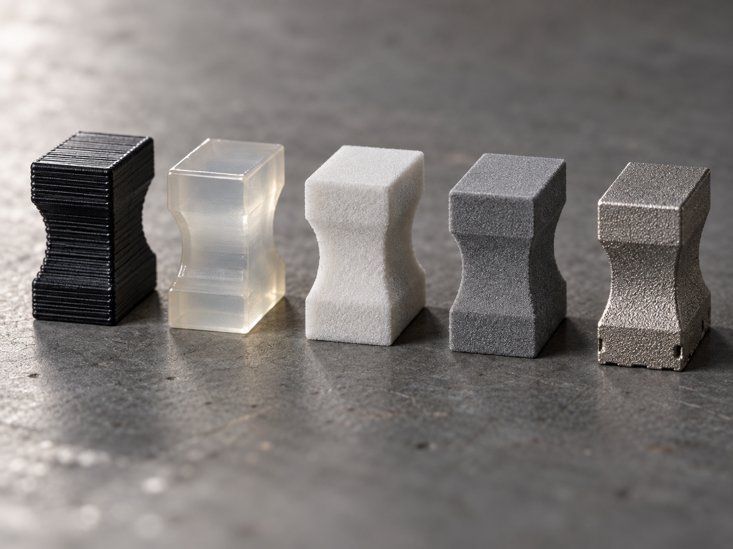
Comparison of mainstream 3D printing processes: how to choose among FDM, SLA, SLS, MJF, and DMLS
The selection order is often reversed. The correct order is: first determine the material, then the process, and finally discuss precision. If the drawing specifies PA12, don't agonize over layer thickness on FDM; if it specifies 316L, only DMLS will do. Conversely, if you pick the process first and then look for a material, you often end up reworking because of strength or heat resistance.
| FDM | PLA, ABS, PETG, PC, nylon | Layer thickness commonly 0.1–0.3 mm; relatively wide dimensional tolerance | Obvious layer lines; Z-direction strength significantly lower than XY | Form verification, jigs and fixtures, large rough prototypes | Volume, support amount, print time |
| SLA | Photopolymer resin (ABS-like, PP-like, heat-resistant resin) | Layer thickness commonly 0.05–0.1 mm; good detail | Fine surface; resin is brittle and has poor weather resistance | Appearance parts, fine structures, prototypes | Volume, supports, post-processing labor |
| SLS | PA12, PA11, glass fiber/carbon fiber reinforced nylon | Layer thickness commonly 0.08–0.12 mm | Anisotropy is smaller than FDM; surface has a powdery feel | Small-batch functional parts, assemblies, snap fits | Powder utilization, build height |
| MJF | PA12, PA12+glass beads, TPU | Layer thickness commonly 0.08 mm | Uniform surface; XY/Z difference slightly smaller than SLS | Small-to-medium batch functional parts, assemblies with moderate appearance requirements | Volume fill rate, batch size |
| DMLS | 316L, 17-4PH, AlSi10Mg, Ti64 | Common layer thickness 0.02–0.05mm; requires heat treatment and support removal | High density; surface requires sandblasting or machining | Metal load-bearing parts, conformal cooling, lightweight structures | Metal powder, supports, heat treatment, and post-machining |
Three quick criteria
- For form and assembly interference verification only: FDM or SLA. SLA has a better surface, but don't use resin parts for load-bearing or long-term outdoor use.
- For assembly strength, batches of tens to hundreds of parts: SLS or MJF. Both suit nylon-type functional parts; MJF batch consistency is usually more stable, while SLS has a more mature material system.
- For metal load-bearing, heat resistance, conformal cooling: DMLS. But accept the post-processing costs upfront: support removal, heat treatment, and machining of mating surfaces often account for more than half of the quote.
A common misconception: using SLA resin parts as structural parts—they crack after two assemblies. Another: using FDM for sealing surfaces—layer lines leak directly. There's only one criterion—material determines the process, not the process determines the material. When the drawing doesn't specify a material, first ask about the application: load-bearing, sealing, heat resistance, or appearance only, then work back to the process.
Six things that must be clearly stated on the drawing: wall thickness, tolerances, mating surfaces, threads, supports, post-processing
3D printing quotes are low and lead times are fast, but many projects fail because of incomplete drawing information. The model is a solid, but process information isn't in the model. Miss any of the six items below and you may have to rework.
Wall thickness and tolerances: give ranges by process, don't specify by machining habits
Minimum wall thickness varies by process. FDM is commonly 0.8–1.2 mm, SLA can be thinner, SLS/MJF commonly around 1.0 mm; these are common industry references, and actual values should be confirmed with the equipment, material, and drawing. Writing only "thin wall" on a drawing is as good as writing nothing. Tolerances must be directional: XY is usually better than Z, and layer thickness determines Z resolution. If a mating surface is specified as ±0.05 while the model is a curved surface, first ask whether the process can reliably achieve it, then decide whether to change the specification or the process.
Mating surfaces, threads, and supports: assembly datums determine success or failure
Place mating surfaces in the XY plane as much as possible; Z-direction layer lines make sliding fits gritty. Don't expect to print threads directly; the common approach is to leave a pilot hole and tap it, or design an insert hole; directly printed threads have low strength and incomplete thread profiles. Support contact surfaces leave rough marks, so the drawing must state whether that surface is acceptable; if not, change the orientation or add allowance for machining. Post-processing (support removal, sanding, sandblasting, dyeing) changes dimensions and appearance and also affects lead time, so it must be stated on the drawing or RFQ.
Orientation determines success or failure: interlayer strength, warping, and support failure modes
The same model, with a different orientation, can differ in tensile strength by more than 30%, and a mating hole can go from passing a go gauge to not fitting at all. FDM, SLA, SLS, and MJF all build layer by layer, and the bond between layers is always weaker than within a layer. Don't design printed parts as if they were isotropic materials.
Load-bearing parts: keep principal stress in the XY plane
If a part bears load—snap fits, fixture clamp plates, load-bearing brackets—first look at the principal stress direction. Lay the part "flat" so tensile stress runs along the XY plane, with the Z direction bearing only compressive stress or no stress. A vertical printed column splits between layers with one bend; the same beam printed flat can withstand significantly greater bending moment. This criterion is more effective than adjusting infill density.
Seals and mating surfaces: don't let layer lines cross the sealing line
If a part needs to seal or mate—O-ring grooves, face seals, sliding fits—the orientation should make the sealing or mating surface an in-layer plane rather than an interlayer step. Layer lines are themselves microscopic grooves, and crossing the sealing line means a leak point. For mating holes, keep the axis horizontal as much as possible (holes formed along the XY direction) to avoid ovality and interlayer steps when the hole axis runs along Z, which cause pin shafts to seize.
Warping and supports: the cost of large flat surfaces and overhangs
With a large flat surface facing down, uneven cooling shrinkage causes corners to lift, a common failure; adding a brim or changing orientation usually controls it. Overhang angles exceeding about 45° (a common industry reference, to be confirmed by specific process and material) generally require supports; support contact surfaces leave rough marks, so don't place assembly surfaces or appearance surfaces facing down. Supports aren't free: one more support means one more support-removal operation and one more dimensional uncertainty.
Order of judgment: first determine the assembly datum and load direction, then determine orientation; if orientation can't be settled, tolerances and post-processing are empty talk. When the drawing doesn't specify orientation requirements, confirm with engineering before quoting—don't wait until it's printed to find it won't fit.
A real case: from "printed but won't fit" to revising the drawing and printing again
Last year, a batch of inspection fixtures, small parts: an 80×60×12 mm locating block with two φ6H7 pin holes, with hole axes originally perpendicular to the large flat surface. The customer was in a hurry to verify assembly and sent the model straight to FDM printing. When the parts arrived, the pins wouldn't go in—the holes measured about 0.15 mm small, and after being forced in they couldn't be removed; the Z-direction layer lines on the hole walls were like fine threads and seized as soon as they were turned.
The review found three problems stacked together: orientation put the hole axis in the Z direction, with weak interlayer bonding and hole diameter shrinkage accumulating along the layer height; tolerance copied machining H7 without leaving allowance for printing; process chose FDM for mating parts. The fix was straightforward: rotate the hole axis to the XY plane, leave 0.1 mm per side on the hole diameter and then ream; change the mating surface to SLA to ensure the surface; change the pin holes to inserts rather than printing them directly. The second version fit in one go.
The lesson from this case isn't that "FDM doesn't work," but that the order was wrong: first determine the assembly datum, then determine the printing direction, and only then choose the process. Once the datum is set, there are criteria for how to orient holes, how much allowance to leave, and whether post-machining is needed. Choosing the process first leaves you passively patching things up afterward.
Inspection and acceptance: how to measure 3D printed parts, what to measure, and which dimensions not to fuss over
The most argument-prone item on a 3D printed part acceptance sheet is measuring a layer-line surface with calipers and then asking "why isn't it Ra1.6." Layer lines, support marks, and step marks are process characteristics of layer-by-layer buildup, not machining defects; holding them to machining surface roughness standards leaves the supplier able only to rework or refuse the order. What should really be held tight are mating dimensions and functional surfaces; appearance surfaces can be accepted as "no obvious visual defects."
Set acceptance criteria by dimension type, not one-size-fits-all
| Dimension type | Measuring tool selection | Acceptance criteria (common references within the job, to be confirmed against drawings) |
|---|---|---|
| Mating holes/shafts (H7, h6) | Plug gauges, inside micrometers, CMM | Must be held tight; FDM/SLA commonly leave 0.1–0.2mm per side allowance then ream or tap, directly printed holes are often undersized |
| Mounting hole center distance | Calipers, CMM | Per drawing tolerances; Z-direction hole spacing is affected by interlayer shrinkage, common deviation is greater than in XY directions |
| Appearance surfaces, non-mating surfaces | Visual inspection, templates | Do not hold to Ra values; layer lines and support marks are process characteristics, only judge for presence of missing material, delamination, warping |
| Thin walls, overhang roots | Visual inspection, calipers | Slight deformation allowed, but no through-cracks; if it affects assembly, judge as nonconforming |
Measuring tools are not better the more expensive they are. For mating holes, plug gauges go/no-go are fastest; save the CMM for first articles and disputed parts; calipers measuring a layer-line surface inherently have several hundredths of uncertainty, and the numbers measured cannot be used as arbitration evidence. If the part has sealing surfaces or sliding mating surfaces, the first article must go on the CMM, and batch parts are sampled with plug gauges plus visual inspection.
The most easily misaligned statement on the procurement side: "quote by model, inspect by machining"
When requesting a quote, only throwing over an STP file means the supplier estimates labor hours by volume and orientation; after arrival, QC takes the machining tolerance table and measures item by item, and as a result the layer-line surfaces and Z-direction hole spacing all "exceed tolerance." The way to avoid misalignment is to write three things clearly at the quoting stage: orientation requirements (which surfaces must face down or up), post-processing requirements (support removal, sanding, sandblasting, dyeing, tapping), acceptance standards (which dimensions are held tight, which only get functional checks). Write these three into the RFQ, and the quote and acceptance will match up. When you need to quickly verify pricing against drawings, you can go through the 3D printing quote entry and submit the requirements together.
One last criterion: dimensions that can assemble, rotate, and seal are held tight; dimensions that merely do not look glossy enough are loosened. Spending inspection resources on functional surfaces is far more worthwhile than spending them on layer lines.
When not to use 3D printing: boundary conditions and small-batch economics
3D printing is not a master key. Batch size is the first hard boundary: when demand for the same part exceeds dozens to hundreds of pieces (the specific threshold fluctuates with part size, material, and post-processing amount, and must be calculated per part), the unit cost of injection molding or hand-made duplicate molds will overtake it. Injection molding requires amortizing mold costs upfront, but once amortized, the unit cost may be only a fraction of printing; the lifespan of vacuum-cast silicone molds is usually dozens of times, suitable for low-to-medium batches.
The second boundary is performance requirements. Layer-by-layer deposition determines that Z-direction bonding is weaker than XY direction. If the part requires isotropic strength, mirror-fit surfaces, long-term weather resistance, or food-contact certification, 3D printing may not be applicable—such needs should turn to CNC, injection molding, or sheet metal. Large solid parts are also not cost-effective: printing time rises steeply with volume and height, and material and machine-time costs rise in tandem.
Simple algorithm: total cost = unit cost × quantity + one-time costs (mold/programming/fixtures). Calculate each of the four paths—3D printing, CNC, duplicate molding, injection molding—and take the one with the lowest total cost. If the quantity falls near the boundary, first print a small batch to verify assembly, then decide whether to open a mold. When requesting quotes, provide the quantity tiers, material, post-processing, and acceptance standards together to avoid the misalignment of "quote by model, inspect by machining." For related process capabilities, refer to the injection molding capabilities and rapid prototyping pages.
Common questions FAQ
The following questions are the ones most often asked during quoting and drawing review. The answers all carry boundary conditions; for your specific part, you still need to look at the drawing and actual working conditions.
Can 3D printing replace CNC machining?
It cannot be generalized. 3D printing is suitable for complex internal cavities, topology-optimized structures, and rapid iterative verification; CNC is suitable for load-bearing parts requiring isotropic strength, mirror-fit surfaces, and high dimensional accuracy. Many projects use a combination: 3D printing for hand samples to verify assembly, CNC for final functional parts. The criterion is—if the part bears load through interlayer bonding, or the mating surface requires a mirror finish, prioritize CNC.
What precision can 3D printing achieve?
Different processes differ greatly. Common FDM dimensional deviation is ±0.3mm or ±0.5%, whichever is greater; SLA/MJF is usually tighter, and DMLS metal parts are different again. Common industry reference ranges can only serve as a starting point for judgment; actual precision is affected by orientation, shrinkage compensation, and post-processing. On drawings, mark XY direction and Z direction separately; do not write only one overall tolerance.
Up to how many pieces is 3D printing cost-effective for small batches?
There is no fixed number. Common experience is that within dozens of pieces, 3D printing is more cost-effective; above hundreds of pieces, the unit cost of injection molding or duplicate molding drops noticeably. But it depends on part size, material, and post-processing amount. It is recommended to amortize mold costs into the batch to calculate total cost, then decide the process; do not look only at the unit quote.
What format should drawings be provided in?
Prefer solid formats such as STEP or IGES; STL is also acceptable but loses surface precision information. At the same time, attach a 2D drawing or annotation file, clearly stating mating dimensions, tolerance zones, post-processing requirements, and acceptance standards. If you provide only an STL with no tolerance description, the factory can only work to default processes, and if it does not assemble, changing it later wastes time.
Will post-processing affect dimensions?
Yes. Support removal, sanding, sandblasting, dyeing, and heat treatment can all change dimensions or surface condition. Support removal leaves marks on contact surfaces, sanding removes material, and heat treatment may cause deformation. If a mating surface is close to a support contact area, note the allowed sanding amount and acceptance datum on the drawing; otherwise disputes easily arise during inspection.
Key takeaways
- First decide "what this part needs to verify," then choose the process: for fit checks only, choose FDM/SLA; for load-bearing or heat resistance, consider SLS/MJF/DMLS. Don't use a prototyping process for a functional part.
- Key items not marked on the drawing—load direction, mating surfaces, threads, sealing surfaces—must be stated at the quotation stage; otherwise they will be interpreted as "appearance part" by default, and dimensions and orientation may both be wrong.
- 3D printing tolerances must be viewed by direction: XY is usually better than Z (between layers). Keep mating surfaces in the XY plane as much as possible, and let the Z direction carry only non-mating dimensions.
- Thin walls, deep grooves, enclosed internal cavities, and overhangs are the four major sources of failure: change the structure if you can; if you can't, write the risks clearly before quoting.
- For small batches (within a few dozen pieces), 3D printing is often more cost-effective than tooling; once you reach several hundred pieces with a fixed material, it's time to recalculate injection molding or vacuum casting.



