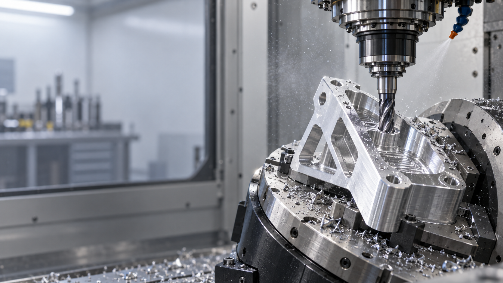
Five-axis does not equal more accurate: what it really sells is "fewer setups"
Many people think the value of 5-axis is "higher precision." The machine tool's own positioning accuracy is indeed one aspect, but for most parts, what truly creates the gap is not the machine tool, but the number of setups. On a 3-axis machine, making an angled-hole bracket requires one setup each for the front face, side face, and angled hole—three alignments, three clampings, with the datum passed back and forth between fixtures, and the accumulated error is often an order of magnitude larger than the machine tool accuracy. Five-axis combines these three faces into one or two setups, cutting the sources of error in half.
In other words, what 5-axis buys is datum unification and process consolidation, not "a more accurate machine tool." For a multi-face housing, if the critical holes are distributed on three mutually angled faces, 3-axis either requires a dedicated fixture or leaves allowance for match machining afterward; 5-axis locks the positional relationship of the three faces in the same coordinate system in one setup, making geometric tolerances easier to guarantee.
Cost leverage ranking: which design choices are quietly adding cost
On a quote for a 5-axis part, the machine hourly rate is only the tip of the iceberg. What truly drives the price apart are several design choices—they are not written in the material column, nor reflected in a single dimension, yet they multiply the workload of programming, setup, tooling, and inspection. Below they are ranked from greatest to least impact, with each item explaining "where the money goes, why, how to save, and when not to save."
- Setup count and datum transfer. Each additional setup means another round of alignment, clamping, and re-inspection, plus accumulated datum error. The value of 5-axis lies mainly here: completing multiple faces in one setup, eliminating repeated positioning. Consolidate processes as much as possible; but if the part has poor rigidity and large overhang, forcing a single setup will instead cause chatter, in which case it is better to split operations and add intermediate inspection.
- Cross-face geometric tolerances. When coaxiality, position tolerance, and perpendicularity are specified on features spanning multiple faces, a single 5-axis setup can maintain datum unification; if the drawing's datums themselves switch back and forth, programming requires additional coordinate systems and inspection requires multiple alignments, increasing cost and disputes. Use a unified datum system for drawing annotation as much as possible.
- Tool accessibility and deep cavities. Deep cavities, narrow slots, and excessively small internal fillets force the use of long-overhang, small-diameter tools, requiring reduced feed rates, more passes, and faster tool wear. Enlarging internal fillets to standard tool radii and controlling the cavity depth-to-tool-diameter ratio during design is the most direct cost-reduction action; but when functional faces require small fillets, do not sacrifice sealing or fit to save tool costs.
- Material and tool wear. Stainless steel, titanium alloys, and high-hardness pre-hardened steel have large cutting forces and poor thermal conductivity, resulting in short tool life and conservative cutting parameters, so labor hours naturally rise. For heat-treatable materials, schedule quenching and tempering after roughing and before finishing as much as possible to reduce hard-state cutting volume; but if dimensional stability requirements are high, hard-state finishing cannot be omitted.
- Surface roughness. Tightening Ra from the common 3.2 to 0.8 or even 0.4 often requires switching to fine milling, adding bench work, or grinding operations. Differentiate roughness by functional face: tighten mating faces and sealing faces, relax non-mating faces. Do not apply one high requirement uniformly across the entire drawing.
- Inspection method. There is a large difference in workload between CMM measurement of every part versus sampling, and 3D scanning full-dimensional comparison. Five-axis parts have many compound angles and spatial curved surfaces, and inspection programming and setup themselves are also time-consuming. For batch parts, agree on the sampling ratio and the scope of the first-article report to avoid defaulting to full inspection.
3-axis, 3+2, and simultaneous 5-axis: first distinguish which one you are buying
"Five-axis" on a quote may refer to two completely different things. 3+2 positioning machining (also called 5-sided or indexed 5-axis) locks the two rotary axes at one angle, and the tool path relative to the workpiece is still 3-axis; simultaneous 5-axis, on the other hand, continuously interpolates the A/C or B/C axes during cutting, with the tool axis vector changing in real time. The price difference, programming labor difference, and accessible surface difference all diverge from here.
Quoting 3+2 as simultaneous, or conversely pricing positioning work at simultaneous rates, is the most common waste in procurement. The table below breaks it down by the four columns "number of machining faces—surface continuity—programming volume—typical applicable parts"; match them before quoting.
| Type | Machinable faces in one setup | Surface continuity | Programming and simulation labor | Typical applicable parts |
|---|---|---|---|---|
| 3-axis | Mainly single face | Flat surfaces, simple steps | Low | Flat plates, single-face cavities, hole systems on a single face |
| 3+2 positioning | Multi-face (still follows 3-axis motion after each angle rotation) | Faces are connected by indexing; transition zones often require stock allowance or manual polishing | Medium; requires establishing a coordinate system face by face | Angled-hole brackets, multi-face housings, parts requiring 3–5 directions covered in a single setup |
| 5-axis simultaneous | Multi-face + continuous compound angles | Can transition continuously; tool axis can follow the surface normal | High; requires RTCP post-processing and collision simulation | Impellers, blisks, complex flow channels, large-curvature thin-wall parts |
How costs diverge: positioning saves setups, simultaneous saves secondary operations
The cost-saving logic of 3+2 is reducing the number of setups: where 3-axis previously required flipping three times and establishing three datums, now it is done in a single setup by rotating the angle. It does not change toolpath complexity, so the programming workload increases only modestly, and the quote is mainly higher in machine hourly rate.
The cost-saving logic of simultaneous is different: what it saves is subsequent operations—the surface is formed in one pass, with no need to leave stock allowance for manual polishing, and no need to make a separate electrode or secondary positioning for the transition zone. The price is a significant rise in programming and simulation man-hours, and greater sensitivity to tool overhang and machine dynamic accuracy. If the part's surface is simple and polishing is inherently inexpensive, the programming premium of simultaneous often cannot be recovered.
- Count the faces first: key features distributed on 1 face → 3-axis; 3–5 directions but each is a flat/angled hole → 3+2; requires continuous transition → simultaneous.
- Then look at transition zone requirements: if the drawing specifies roughness or profile requirements at the junction of two surfaces and manual rework is not allowed → evaluate as simultaneous.
- Finally, ask about inspection: if cross-face geometric tolerances would require establishing datums multiple times on 3-axis, 3+2 can unify the datum in a single setup; this benefit is often overlooked.
When 5-axis is actually more expensive: three scenarios where it should not be used
In a 5-axis quote, machine hours are only part of it. What really drives the price up are three hidden costs: programming, tooling, and setup rigidity. For the following three types of parts, forcing 5-axis is usually not cost-effective.
- Mainly single-face flat milling: all key features of the part are in the same direction, and 3-axis can complete it in a single setup. The value of 5-axis lies in "fewer flips," but here there is no flipping to begin with; what is added is only programming time and the positioning error chain of the rotary axes.
- Loose tolerances, two setups are enough: if the cross-face geometric tolerances themselves are loose (for example, position tolerance per general tolerances), using 3-axis with one flip and re-aligning the datum is lower cost. Forcing 5-axis instead means paying for expensive simultaneous toolpaths for a tolerance that is not sensitive.
- High volume, dedicated fixture already exists: once production volume ramps up, a dedicated fixture can push the cycle time of a 3-axis line very low. The advantage of 5-axis saving setups per piece is diluted by the fixture's fixed cost in the face of volume. At this point, the better question is "can the fixture be improved further," not "should we switch to 5-axis."
Forcing 5-axis often exacts its price in places you cannot see: programming changes from 2.5-axis toolpaths to simultaneous toolpaths, increasing trial cuts; ball-nose tools and long-overhang holders lose rigidity, making thin walls and deep cavities more prone to chatter; the workpiece swings with the rotary axes, so the fixture must be redesigned, and fewer clamping points in turn forces lower cutting parameters. All of these appear on the quote in the form of "process difficulty."
The rule is simple: if the setups saved cannot pay back the increase in programming and tooling, 5-axis should not be used. Only when a part requires multi-face machining and these faces have strict mutual positional requirements does 5-axis truly begin to pay off.
Four things to specify clearly on the drawing: datums, tolerance zones, roughness, inspection
5-axis saves setups, but it does not save you from "how to annotate." If the drawing annotations are unclear, the machining side can only work according to its own understanding, while the inspection side verifies according to another understanding, and in the end all disputes land on rework. For 5-axis parts, focus on four things.
Datum system: one primary datum, don't make the inspection side guess
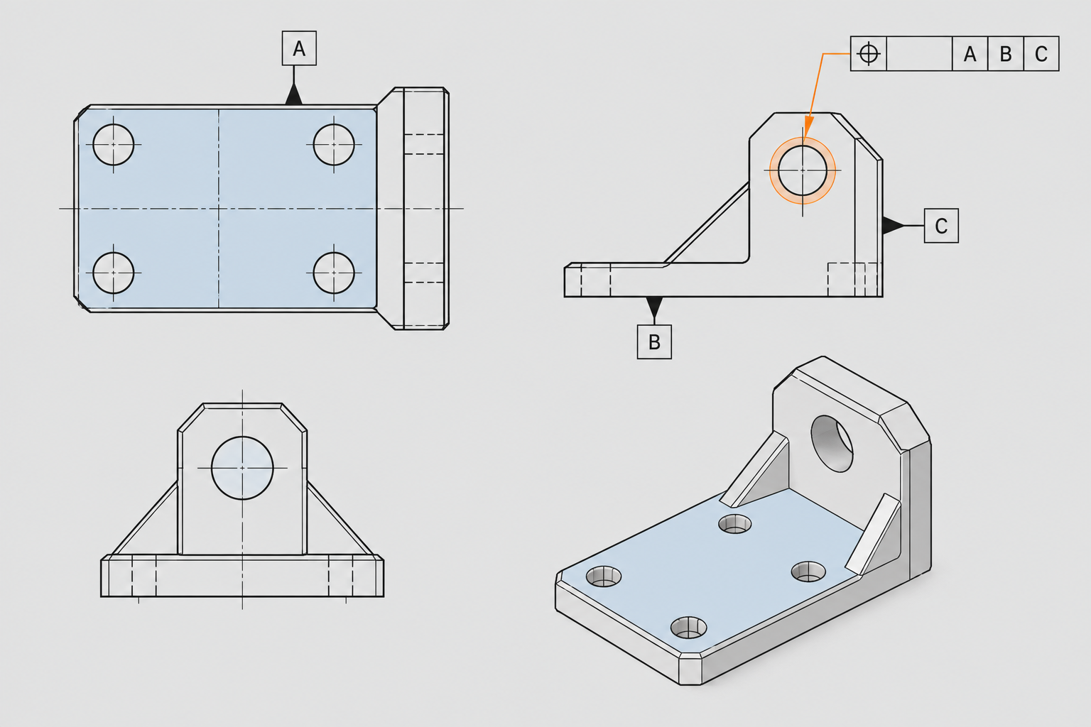
5-axis parts often produce multiple faces in a single setup, and the most error-prone issue is not machining but datum transfer. If the drawing sets face A as the datum but the critical hole positions are annotated on face B, then inspection requires datum transfer between A and B, amplifying error. A common practice is: choose the face most relevant to assembly function as the primary datum, and annotate other features to that datum as much as possible; if cross-face annotation is truly necessary, specify the datum system clearly (e.g., A|B|C), don't just drop a single symbol.
Geometric tolerances: annotate cross-face features, not just dimensions
The value of 5-axis lies in cross-face machining, so the drawing must indicate cross-face relationships. Geometric tolerances such as position, perpendicularity, and coaxiality constrain assembly better than single dimensions. If only hole diameters and coordinates are annotated without position tolerance, the machining side will work to machine accuracy while the inspection side verifies to assembly function, and no one can say clearly how much the difference is. A common industry practice is: use position tolerance with maximum material requirement for mating holes, use profile tolerance for contour surfaces, and don't pile up a bunch of linear dimensions.
Roughness and inspection: distinguish by function, agree in advance
Roughness is not better the lower it is. Sealing faces and sliding fit surfaces require lower Ra, while non-mating faces are fine at Ra 3.2 or even 6.3; marking Ra 0.8 across the entire drawing only makes the machining side run more finishing toolpaths and spend more time. The inspection method must also be specified in advance: CMM for geometric tolerances, 3D scanning for contour comparison—the two differ in cost and lead time, and if the drawing does not specify, both quoting and acceptance will lead to disputes. For uncertain roughness values, annotate separately by functional face; don't use a blanket "overall Ra 1.6."
if/then decision rules
- If key features span more than two faces → establish a unified datum system, annotate position or profile tolerance, and do not give only coordinate dimensions.
- If a face only serves as support and does not participate in mating → relax roughness to Ra 3.2–6.3 to reduce finishing toolpaths.
- If assembly is sensitive to coaxiality → annotate coaxiality rather than only diameter tolerance, and specify the inspection method (CMM).
- If the contour is a free-form surface → use 3D scanning comparison, provide the CAD model and profile tolerance zone on the drawing, and do not describe it with linear dimensions.
A rework case of a bracket: the setups saved were eaten up by out-of-tolerance
For an aluminum alloy bracket, four of its six faces have machined features, and there are two sets of φ8 locating holes on an inclined face. The original process used 3-axis machining, requiring three setups; after switching to 5-axis with a single setup, machining time did drop. But when the first article CMM report came out, the position of the inclined-face holes relative to datum A was out of tolerance, and the gauge judged it unacceptable. The dispute is not about the machine tool, but about the drawing: datum A is marked on the bottom face, yet the critical hole position tolerance is marked on face B of the inclined surface. Inspection establishes its coordinate system from face B, while machining locates from face A—the two datums are not aligned.
This is the account most easily overlooked on 5-axis parts: setup count is saved, but datum consistency has not kept up, and the time saved is eaten up by inspection disputes and rework.Setup cost is explicit, while datum conversion cost is implicit, and the latter is often more expensive.
if/then: when to save on setups, and when to change the drawing first
- if the critical geometric tolerance involves only a single datum face, and inspection can establish its coordinate system from the same datum → a single 5-axis setup is a net gain, so go with it directly.
- if the tolerance spans faces (datum on face A, feature on face B), but engineering is willing to unify the datum system → change the drawing first, then plan the process; do not let machining and inspection each work to their own datum.
- if the tolerance spans faces and the datum cannot be changed (assembly constraints are locked) → machine from face A and also establish the inspection coordinate system from face A, convert the face B tolerance to be dimensioned from face A, or note the inspection datum on the drawing.
- if the customer provides only a finished-part drawing and no datum explanation → confirm the inspection datum in writing before quoting; otherwise the probability of a first-article dispute is not low.
The lesson from this case is not “don’t use 5-axis,” but rather that 5-axis saves setups, not datum management. Producing multi-face features in a single setup actually exposes the problem of inconsistent datums earlier. If the drawing does not clearly specify the inspection datum, the more setups you save, the greater the dispute during rework.
How purchasing and inspection should coordinate: information to exchange before quoting
Quotation fluctuations for 5-axis parts are often not due to machining hours themselves, but because the inspection logic was not made clear before quoting. For the same drawing, the price difference between quoting “CMM sampling of critical holes” and “full-dimensional first-article report + 3D scan comparison” is usually larger than changing materials. The reason is simple: 5-axis parts usually complete multiple faces in one setup, and inspection must unify multiple coordinate systems into one datum, which increases both programming and measurement time.
Five inputs that must be exchanged before quoting
- Material and condition: grade, heat treatment condition, blank form (plate/forging/bar stock). Large forging allowance directly changes setup and toolpath strategy.
- Quantity and batch: one-off, small batch, or repeat batch. Quantity determines whether it is worth making dedicated soft jaws or locating fixtures.
- Critical tolerance list: which dimensions/geometric tolerances are functional and which are only reference. 5-axis quotes are calculated by critical features, not averaged across the entire drawing.
- Inspection requirements: whether a first-article report is required, whether CMM or 3D scanning is specified, and the sampling ratio. This determines inspection hours and is the most easily overlooked item in a quote.
- Datum and drawing version: datum system, whether there are cross-face geometric tolerances, and version number. Unclear datums are the main source of subsequent rework and disputes.
First article and production inspection are not the same thing
First articles usually require full-dimensional verification, including datum establishment, cross-face position, and profile tolerance, and inspection time may approach or even exceed machining time. In the production phase, this generally shifts to sampling critical dimensions, and cost falls. If purchasing writes first-article requirements into a production order, it is equivalent to paying for 100% inspection. A common practice is: release the first article based on a full-dimensional report, and inspect the production batch according to agreed sampling items; but when the drawing does not specify sampling rules, confirm with engineering—do not assume the supplier will perform 100% inspection.
The inspection cost of 5-axis parts is higher than that of 3-axis parts, mainly because of datum unification for multi-face features and curved-surface profile measurement. Most faces of 3-axis parts are orthogonal, and gauges and calipers can cover most of them; 5-axis parts often have inclined holes, compound-angle faces, and continuous curved surfaces, so CMM or scan comparison is required, and the measurement path itself must be programmed. To reduce this cost, the most direct method is to reduce cross-face tolerances—features that can be placed on a single datum should not be dimensioned to another face.
Another purchasing-side criterion: if the part has mating faces or assembly datums, inspection items should follow the assembly, not the machined face. A machined face being easy to measure does not mean assembly will pass. Aligning the two usually significantly reduces rework rates. For CNC machining capabilities and inspectable scope, refer to CNC machining capabilities; confirm the specific inspection plan according to the drawing.
Common questions about 5-axis machining
The following are the most frequently asked before quoting. The answers give judgment criteria, not guaranteed values—whether something can actually be achieved depends on drawing tolerances, material, and inspection method.
What precision can 5-axis machining achieve?
The positioning accuracy of the machine itself is usually not the bottleneck; setup rigidity and thermal deformation are. A common industry practice is: for general structural parts, position tolerances are controlled in the ±0.02–±0.05 mm range, with mating faces tightened according to the drawing; curved-surface profile is mostly in the 0.03–0.08 mm range. These are only reference bands, not guaranteed values. What really determines success is whether the datum is unified, how long the tool overhang is, and whether roughing and finishing are separated. If the drawing specifies ±0.01 mm cross-face position tolerance, first confirm whether the inspection method can measure it before discussing machining.
Is 5-axis always more expensive than 3-axis?
Not necessarily, but in most cases the unit price is higher. 5-axis is expensive because of longer programming time, limited tool overhang, and specially designed setup plans. If a part originally requires three setups and accumulated datum errors cause rework, a single 5-axis setup may instead save rework and inspection costs. Conversely, putting a single-face flat milling part on 5-axis just makes a simple job complex, with money spent on programming and machine adjustment—not worthwhile. Judgment criterion: when setup count ≥3 and geometric tolerances span faces, 5-axis is worth calculating.
How to choose between 3+2 positioning and 5-axis simultaneous machining?
It depends on whether the surface is continuous. 3+2 locks the two rotary axes and machines at a fixed angle, suitable for multi-face drilling, inclined-face milling, and parts mainly composed of flat faces, with better programming and rigidity. 5-axis simultaneous machining interpolates two axes at the same time during machining, suitable for continuous curved surfaces, compound angles, and impeller-type flow channels. A common mistake is comparing a 3+2 quote against simultaneous work: if the drawing requires continuous curved-surface profile tolerance, 3+2 will produce tool marks and surface steps, and rework will be more expensive. State the curved-surface requirements clearly before quoting.
Is 5-axis worthwhile for small batches?
Small batches are precisely where 5-axis has an advantage, because dedicated fixtures and multiple-setup locating tooling are eliminated. But the premise is that the part has cross-face tolerances or complex angles. If it is just a few dozen simple plate parts, 3-axis plus simple fixtures is more economical. Judgment rule: small batch + many setups + cross-face geometric tolerances → 5-axis; small batch + single-face machining + loose tolerances → 3-axis. Do not use 5-axis just for the sake of “using 5-axis.”
How are 5-axis parts inspected?
Prefer a coordinate measuring machine, establish the coordinate system according to the drawing datum, and focus on measuring cross-face position and profile. For complex curved surfaces, 3D scanning can be used for surface-deviation comparison, but the scan results must be aligned with the CMM datum; otherwise the data will not match. Inspection cost is usually higher than for 3-axis parts because there are more datum conversions and denser measurement points. It is recommended to agree on the inspection method at the time of quoting: full-dimensional report for the first article, and sampling of critical dimensions for production. Inconsistent inspection criteria are where 5-axis parts generate the most disputes.
Key takeaways
- First count the setups: only when a part requires more than 3 setups to complete its critical faces can 5-axis possibly be worthwhile; for 2 or fewer, prioritize 3-axis.
- Geometric tolerance is the first criterion for 5-axis: when position tolerance, coaxiality, and profile tolerance span multiple faces, the benefit of a single setup far exceeds tightening tolerance on a single face.
- Deep cavities, negative angles, and tool holder interference faces are places where 3-axis tools cannot reach, and are also the scenarios where 5-axis truly saves labor hours.
- Do not use 5-axis to rescue a drawing whose tolerances are inherently unreasonable: the money saved on setups will be eaten up by out-of-tolerance scrap.
- Before quoting, clearly specify the datum, tolerance zone, surface roughness, and inspection method; otherwise the price difference between 5-axis and 3-axis cannot be judged as worthwhile.



