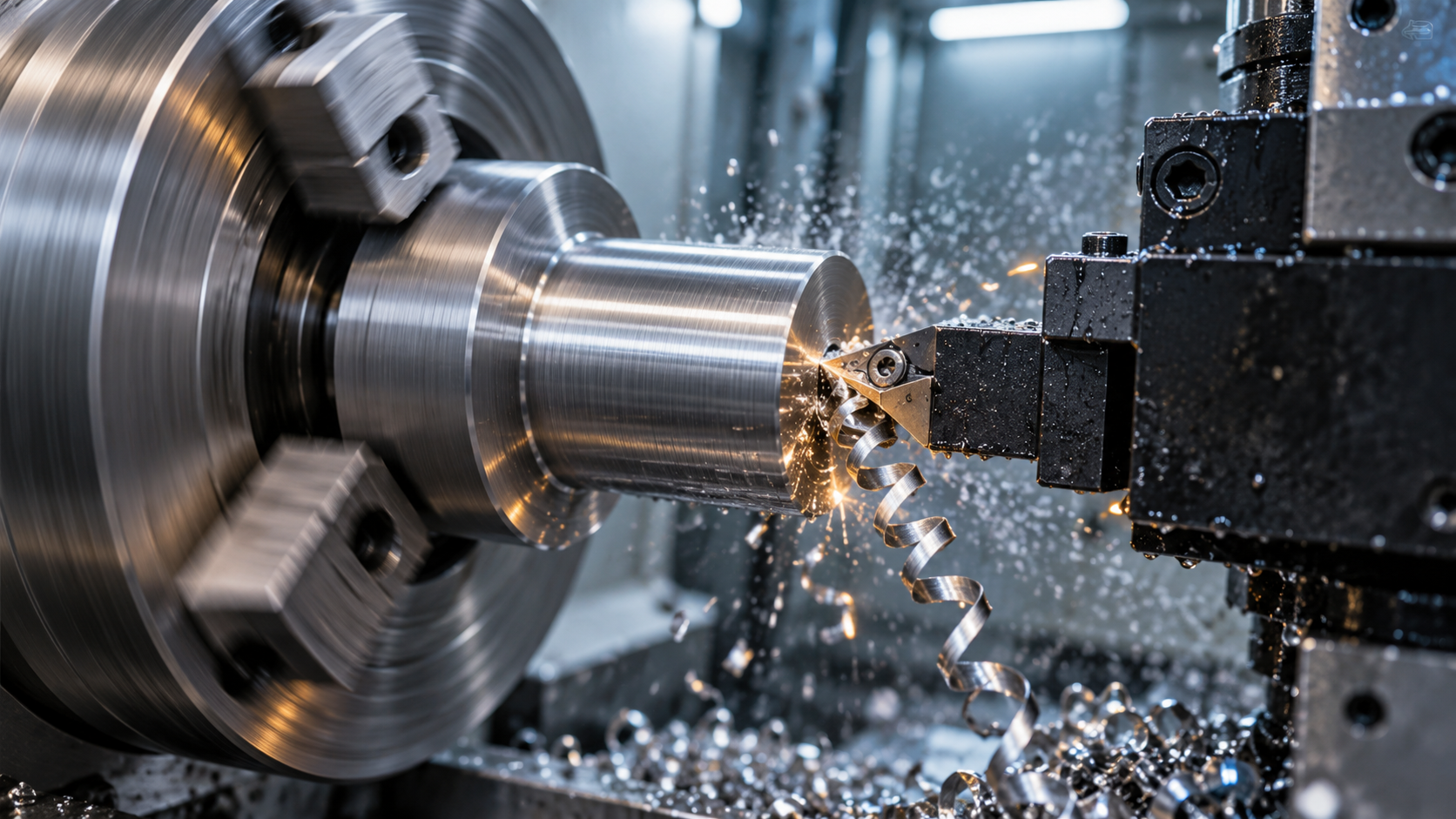
What Is Lathe Machining: The Workpiece Rotates, the Tool Moves
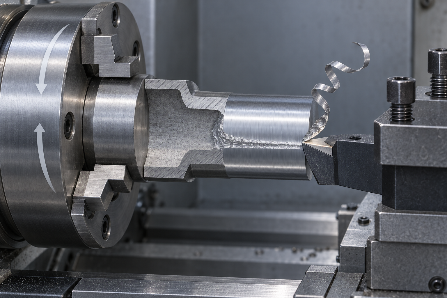
Lathe machining is a manufacturing process that makes the workpiece rotate while the tool moves. Specifically, a bar or blank is clamped by a fixture, and the spindle drives it to rotate at high speed; the lathe tool itself basically does not move, only feeding along the axial or radial direction, cutting away excess material layer by layer. It belongs to "subtractive manufacturing," the exact opposite of "additive manufacturing" like 3D printing, which builds material up little by little.
To quickly understand this motion, think of a potter's wheel throwing clay. The clay blank sits on the rotating wheel, your hands are stationary, and you shape the clay into round jars and bowls by the position and pressure of your hands. Lathe machining is the metal version of this logic: what rotates is the workpiece, and what controls the shape is the position and feed of the tool. Precisely because of this, a lathe is inherently good at making rotationally symmetric parts such as cylindrical and conical ones—shafts, sleeves, discs, bolts, and pipe fittings all depend on it.
The history of lathe machining is longer than most people imagine. Ancient Egypt already had the prototype of the bow lathe, using a rope pulled back and forth to make wood rotate while a person held a tool to cut it. From "pulling a rope by hand" to "a motor driving the spindle," and then to today's CNC systems, the core motion has actually not changed—what has changed is speed, precision, consistency, and who controls that tool.
Here is a judgment that will be used repeatedly later: to judge whether a part should be machined on a lathe, first see whether it is symmetric about some axis. If the main shape of the part can be described by "one axis + one rotational profile," lathe machining is usually the first choice; if not, then milling or another process should be considered. This criterion runs through the entire article, and the next section will use it to completely separate lathes from milling machines.
What Is the Difference Between Lathe Machining and Milling Machining?
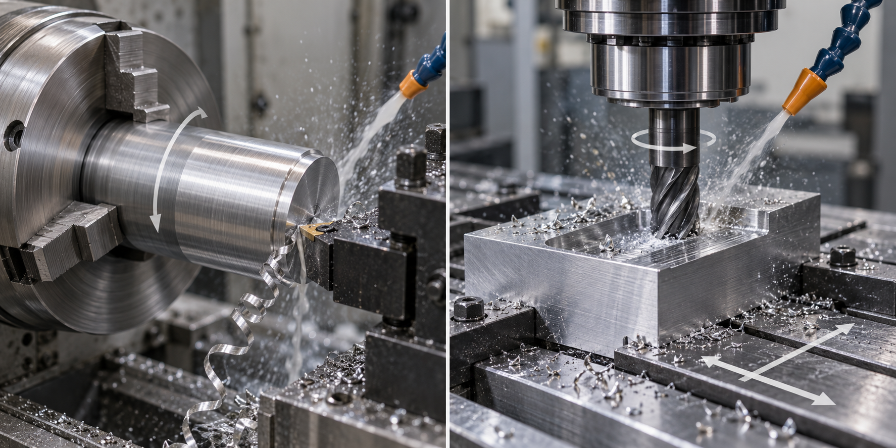
Put a lathe and a milling machine side by side, and the most intuitive difference is just one word: who rotates. In lathe machining, the workpiece rotates and the tool basically does not move—the chuck clamps the bar and the spindle drives it to rotate at high speed, while the lathe tool slowly feeds along the axial or radial direction, cutting the external cylinder pass by pass. A milling machine is exactly the opposite: the tool rotates at high speed and the workpiece is mounted on the worktable and moves, with the milling cutter's edges biting into the stationary workpiece.
This directional difference directly determines the different shapes the two machine tools are good at making, and also explains why two features on the same drawing often have to be made on two different machines.
A down-to-earth analogy is easy to remember: a lathe is like a potter's wheel, where the clay blank rotates on the wheel and the hands are stationary, shaping it by position and pressure, and what comes out is naturally round and symmetric; a milling machine is like carving, where the block stays still and the graver moves in your hand, able to cut straight lines, grooves, and arbitrary contours. Once you understand these two motions, what a lathe can do and what a milling machine can do can basically be derived on your own.
Lathes are good at rotational bodies, milling machines are good at non-rotational surfaces
Because the workpiece rotates, parts produced by lathe machining naturally have a rotational axis: shafts, sleeves, discs, flanges, and threaded fittings—parts whose main body is round—are made quickly and accurately on a lathe. Requirements such as coaxiality and roundness can be guaranteed in one or two setups on a lathe, because all surfaces are turned around the same axis.
Milling machines, on the other hand, are good at planes, keyways, polyhedra, irregular contours, and hole systems. These features do not have a unified rotational center and require the tool to engage at different positions and angles, relying on the worktable or spindle to follow a path. Therefore, for parts such as housings, plates, and brackets, the first choice is usually a milling machine rather than a lathe.
| Comparison dimension | Lathe machining | Milling machining |
|---|---|---|
| Main motion | Workpiece rotation | Tool rotation |
| Feed | Tool moves axially/radially | Workpiece or tool moves along multiple axes |
| Shapes it excels at | Rotational bodies such as shafts, sleeves, discs, and threads | Planes, slots, polyhedra, and irregular contours |
| Typical precision characteristics | Coaxiality and roundness are easy to control | Flatness, hole positions, and contour precision are easy to control |
| Analogy | Pottery wheel | Engraving |
Real parts often require a combination of turning and milling
In reality, parts are rarely completed by just one method. Take a drive shaft, for example: the main outer diameter, end faces, and center hole are turned on a lathe, while the keyway on the shaft, threaded holes on the end face, or flats must be machined on a milling machine. The process sequence is usually turning first, then milling—establish the rotational datum first, then use that axis as the reference to mill other features, which gives more stable positional accuracy.
If a part has many features and the batch size is not large, you can also consider a turn-mill combined machine, which completes the outer diameter, end faces, side slots, and holes in one setup, reducing datum errors caused by repeated clamping. However, whether to use a turn-mill combined machine depends on the part's structural complexity and batch size—for parts with simple features and large batches, using two separate machines is actually more economical. For specific plans, it is recommended to confirm with a process engineer before quoting. You can learn about our turning and milling scope on the CNC machining capabilities page.
What types of lathes are there: from manual to Swiss-type
Now that you understand the core motion of lathe machining—"the workpiece rotates, the tool moves"—the next question is: who controls this motion, and what structure is used to achieve it. A lathe is not a single machine model, but a family divided into several categories by control method and structural design. Understanding these categories is what allows you to judge which type of machine a drawing should be assigned to.
By control method: manual lathes and CNC lathes
The broadest division is based on who "turns the handwheel." Manual lathes rely on the operator turning handwheels to control the tool's longitudinal and cross feeds, with dimensions depending entirely on the human eye, feel, and repeated measurement with gauges. Its advantages are simple structure and intuitive operation, suitable for one-off repair fitting, teaching, and on-site emergency machining; its disadvantage is that when making a second piece to the same dimension, consistency depends on human stability.
CNC lathes hand the motion over to a program: the operator writes the tool path, spindle speed, and feed into G-code in advance, and the machine automatically moves the tool according to the instructions. Running the same program for a hundred pieces, every piece follows the same tool path, so dimensional consistency is clearly better than manual operation, and complex contours and arcs do not need to be finessed by feel. Today, when people mention "lathe machining," most of the time they already mean CNC lathes by default—manual lathes still exist, but once batch production and precision requirements come into play, they basically all shift to CNC machines.
By spindle and guide bushing design: Swiss-type and turret-type
Within CNC lathes there is a more engineering-oriented fork in the road, based on "how the material is fed and how the tool moves."
- Turret-type lathe: the bar stock or chuck-held workpiece rotates at the spindle, and the turret tool holder carries the tool as it moves in to cut. This is the most common and most intuitive lathe form, with good rigidity, suitable for workpieces of larger diameter and relatively short length.
- Swiss-type lathe: the material is fed forward through a guide bushing, and the tools cut radially around the guide bushing—the workpiece rotates while being "pushed" along, with the cutting point always close to the guide bushing. This structure gives slender parts support from the guide bushing during machining, making them less prone to tool deflection and bending, so it is especially suitable for small-diameter, high length-to-diameter ratio precision parts.
| Comparison dimension | Swiss-type | Turret-type |
|---|---|---|
| Machining principle | Material is fed through a guide bushing, and the tool cuts radially near the guide bushing, with the cutting point supported | The workpiece rotates at the spindle, and the turret tool holder drives the tool to move and cut |
| Applicable products | Small-diameter, high length-to-diameter ratio slender precision parts, such as shaft pins, connectors, and small medical and electronic parts | Workpieces of larger diameter and shorter length, such as discs, sleeves, flanges, and general shaft parts |
| Machining outer diameter | Commonly used in the industry for about 42mm and below, mostly small-diameter precision parts | Commonly used in the industry for about 42mm and above, with small-diameter models also available |
| Precision and surface finish | Due to guide bushing support, slender parts are less prone to tool deflection, and dimensional consistency and surface quality are usually better | Good rigidity, suitable for larger cutting volumes; precision can also reach the micron level, depending on the machine and process |
The number "42mm" is often used as a rough dividing line: for parts smaller than it and slender, Swiss-type is often more suitable; for parts larger than it and not long, turret-type is more common. But this line is not a hard rule—machine model, material, tolerance requirements, and batch size all affect the choice. Taking the drawing to go over it with a process engineer is more reliable than memorizing numbers.

What shapes and features can a lathe machine
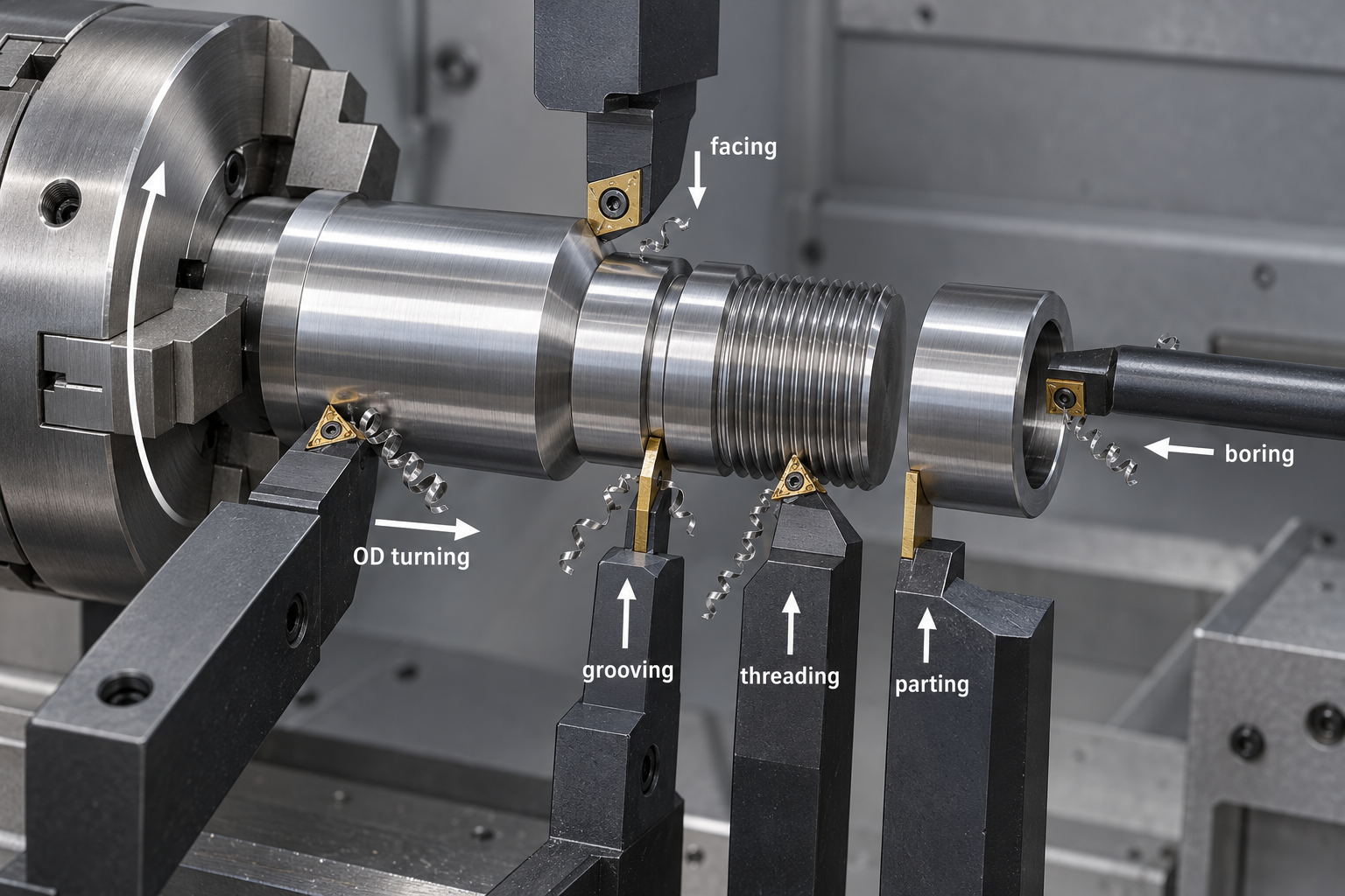
Outer diameter machining: turning the outer contour of a body of revolution
Inner diameter and boring: making holes larger, more accurate, and smoother
Facing, drilling, and parting off: turning bar stock into a single part
Threads, grooves, and tapers/arcs: the ability to stack features
How lathe machining is done: from drawing to finished part
What was discussed earlier is all about "what a lathe can do." This section takes a different angle: when a drawing is handed to the workshop and finally becomes a part whose dimensions can be measured, what actually happens in between. The process itself is not mysterious; what is difficult is that every step involves trade-offs, and every trade-off leaves a trace on the final dimensions.
Step one: the drawing and modeling establish the datum
How lathe machining is done does not start with the machine tool, but with the drawing. The design side first produces a 3D model, then converts it into an engineering drawing, marking diameters, lengths, tolerance zones, material grades, surface roughness requirements, and geometric tolerances—coaxiality, circular runout, end face perpendicularity, and so on, which are especially critical for rotational parts. The most easily overlooked point in lathe machining is the datum: which face or which section of outer diameter is datum A on the drawing directly determines where to clamp first and which end to turn first during setup. If the datum is not aligned, all subsequent dimensions will deviate accordingly.
If it is a simple rotational part, a 2D drawing plus a few key dimensions is enough; if it is a multi-step shaft or a sleeve-type part with an inner bore and threads, a complete engineering drawing is usually required, with the tolerances of each feature marked separately. Roughness cannot be written simply as "Ra 1.6" either; it must be clear which surfaces—the roughness achievable by turning differs from that by grinding, and the callouts must match the process.
Step two: programming, translating the drawing into toolpaths
CNC lathes cut according to a program. There are two paths for programming: use CAM software to generate toolpaths directly from the model and export G-code, or have a process engineer write it manually based on the drawing. CAM is efficient and less likely to miss features, but handling complex internal cavities and irregular contours requires manual intervention; manual programming is actually faster for simple shaft-type parts and more flexible to modify.
The program must define several things: the toolpath route, the tool change point for each tool, spindle speed and feed, and the depth-of-cut allocation for roughing and finishing. Roughing pursues removal efficiency, while finishing pursues dimensional and surface quality; the parameters of the two cannot be mixed. If the program is written incorrectly, at best the surface will have chatter marks, and at worst there will be a tool crash—so the first run usually requires single-block or dry run to confirm the trajectory.
Step three: selecting the blank, setup, and tool setting
The blank can be bar stock, a forging, or a casting. Bar stock is the most commonly used; when selecting the diameter, leave machining allowance. Forgings and castings have larger allowance but are closer to the finished shape, saving material and labor hours. The clamping method determines rigidity and datum: a three-jaw chuck is suitable for regular cylindrical parts, a collet is suitable for small-diameter parts with high coaxiality requirements, and soft jaws can be turned to an arc surface matching the workpiece to reduce clamping marks and deformation. Slender shafts also require a steady rest or follower rest, otherwise the cutting force will bend them as soon as it presses down.
Tool setting is telling the system the position of the tool tip. If tool setting is inaccurate, the dimensions will shift as a whole; if tool setting repeatability is poor, batch parts will vary in size from one to the next. This step looks like just "touching off," but in fact, together with setup, it determines the dimensional consistency of the entire batch of parts.
Step four: trial cutting, cutting, and inspection
The first part is usually trial cut first. The purpose of trial cutting is not to "see whether it can be turned," but to verify dimensions, surface roughness, and whether chip evacuation is normal. If the dimensions are off, determine whether it is tool wear, thermal deformation, or tool setting error, then decide whether to compensate the tool or adjust the program. Once the parameters are set, automatic cutting begins, and the operator must watch the chip color, sound, and load meter—abnormalities often appear here first.
Inspection uses calipers and micrometers to measure outer and inner diameters, a bore gauge to measure hole diameter, and a projector or CMM to measure contours and position. In batch production, first article inspection and patrol inspection are also required to confirm that dimensional drift is within the tolerance zone. Turning accuracy can usually reach the micron level, but exactly how far depends on part rigidity, material, tooling, and machine condition, and cannot be generalized—the common industry statement is micron level, but in practice the drawing requirements and process evaluation prevail.
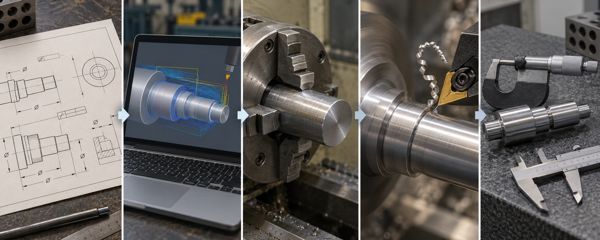
These five steps form a closed loop: the drawing sets the datum, programming sets the path, setup and tool setting set consistency, cutting sets the surface, and inspection determines acceptance. If any step is relaxed, the final dimensions will speak for themselves. To run through this process with your own drawing, you can start by uploading it through AI chat quote or classic quote, first reviewing the process feedback, then deciding how to revise the design next.
Why lathe machining is said to be difficult
The previous section broke the process into six steps, which looks like a smooth assembly line. But those who have actually spent time in the workshop know that lathe machining has never been a process of "press a button and the part comes out." With the same drawing and the same machine tool, two machinists may produce one part that passes inspection directly and another that requires repeated rework. The difficulty is not in the equipment itself, but in the series of variables behind the equipment that require human judgment.
The drawing is the first filter
The drawings faced in lathe machining often involve more than just one outer diameter dimension. A shaft may simultaneously be marked with coaxiality, roundness, end face perpendicularity, several grooves, and a section of thread, with surface roughness also divided into several grades. After geometric tolerances are stacked, the machining sequence of each feature will affect the datum. Which end to turn first, which face to use as the datum, and whether to turn around for a second setup—these judgments must be thought through before programming.
Roughness requirements are also an invisible threshold. A drawing marked Ra 1.6 versus Ra 0.4 corresponds to completely different tool edge geometry, spindle speed, and feed rate. The former may be achieved in one pass with conventional turning, while the latter often requires leaving finishing allowance, changing to a finishing tool, and reducing feed. If these callouts are not understood, the dimensions may be correct, but the surface may not pass inspection.
Choose the wrong tool and everything afterward is wasted
The types of tools used in turning are more numerous than outsiders imagine: OD turning tools, facing tools, internal boring tools, grooving tools, threading tools, and parting tools, each with different tool nose radius, rake angle, and material. Machining steel and machining aluminum use different grades and coatings, and machining stainless steel is prone to work hardening. Choosing the wrong tool or the wrong angle can at best cause chatter marks and dimensional drift on the surface, and at worst cause tool tip chipping and scrap of the workpiece.
What is more troublesome is internal bore machining. The longer the boring bar overhang, the worse the rigidity, and deep hole machining is prone to tool deflection and taper. Experienced machinists will first rough bore leaving allowance, then change to a more rigid bar for finish boring, and if necessary take several passes. This strategy is not written into the program; it relies on empirical judgment of the material and bar rigidity.
Set the cutting conditions wrong and the machine will immediately "protest"
Among the three parameters—spindle speed, feed, and depth of cut—if any one is off, it will leave traces at the cutting site. If the speed is too high and the feed is too large, the tool tip temperature rises sharply, and carbide may wear rapidly due to insufficient red hardness; if the depth of cut is too large, the machine spindle load rises, a slender workpiece deflects directly, and the turned diameter becomes thick in the middle and thin at both ends. Conversely, if the parameters are too conservative, efficiency is low, and extrusion marks may also be left on the workpiece surface.
Chatter marks are another typical signal. The workpiece, tool, tool holder, and chuck form an elastic system. Once the cutting force frequency hits the natural frequency of the system, regular ripples will appear on the surface. Adjusting the spindle speed, changing the tool nose radius, shortening the overhang, and adding a steady rest are all common countermeasures, but exactly how to adjust depends on listening to the sound and observing the chip color and shape on site.
Thin-walled parts and slender shafts are two classic challenges
For thin-walled sleeve-type parts, if the clamping force is slightly too large, they become oval, and when the chuck is released they spring back partly, with dimensions fluctuating between the "clamped state" and the "free state." Slender shafts are another kind of deformation: once the length-to-diameter ratio is large, the cutting force bends the workpiece, causing deflection in the middle and oversized dimensions at both ends. Such jobs usually require reducing the depth of cut, increasing the spindle speed, using a follower rest or steady rest for auxiliary support, and even splitting roughing and finishing into two operations to let it release stress.
There is no one-size-fits-all formula for these countermeasures. For the same shaft, if the material changes from 45 steel to 304 stainless steel, the work hardening tendency differs, and the parameters must be readjusted; if solid bar stock is changed to seamless tube, the clamping method must also change accordingly. That is why experience in lathe machining is valuable—it is valuable in being able to judge the cause of an abnormality and adjust, not just in being able to operate the panel.
This is also why capability pages such as CNC machining present material, tolerance, and surface requirements together—whether a part can be produced stably depends on whether the drawing requirements, material characteristics, and process strategy match, rather than looking only at the machine model. The next article continues with when lathe machining should be prioritized and when another process should be used instead.
When should you choose lathe machining?
The previous sections have dissected the idea of "the workpiece rotates, the tool moves" in enough detail. When it comes to the selection decision, you really only need to ask one question first: Is the main body of this part a body of revolution around an axis? If the answer is "yes," lathe machining is usually the first choice, and you may not even need to compare prices.
Three types of parts for which lathe machining should be prioritized
Shafts: motor shafts, transmission shafts, pin shafts, stepped shafts. The key dimensions of such parts are the outer diameters of each section and the coaxiality between steps. Turning them continuously in one setup naturally gives better coaxiality than "milling, then milling again." If the drawing specifies a runout geometric tolerance, the lathe is almost the only method that is not awkward.
Sleeves and discs: bearing sleeves, bushings, flanges, end caps. Both the inner and outer circles need machining, and they may also have end-face seal grooves and threads. For these parts, the lathe can perform the widest range of operations, and the workholding is the most mature—once clamped in a three-jaw chuck or collet, the coaxiality of the inner and outer circles is secured.
Fittings and threaded parts: pipe fittings, studs, adapters with internal and external threads. Thread machining itself is the lathe's signature operation, especially for non-standard pitches and tapered threads, which milling machines or dies can hardly replace. When batch consistency requirements are high, a CNC lathe controls the feed of every cut through the program, making it far more stable than a manual lathe.
In these cases, don't force it onto a lathe
For plates, box-type parts, and multi-face irregular parts, the main body is not a body of revolution, so a milling machine or sheet metal is more cost-effective. If a 200×200 square plate needs an irregular cavity cut out, once the lathe starts rotating, there is no clamping datum to be found. There is another easily overlooked case: slender shafts with a large length-to-diameter ratio and thin walls. During turning, they are prone to tool deflection and chatter marks, requiring a follow rest or steady rest for support. At that point, you need to evaluate process feasibility—it is not a question of "can it be turned," but of "will it come out stable when turned."
By the way, lathe machining and milling machining are not mutually exclusive. Many parts are "first turn the outer diameter, then go to the milling machine to cut a keyway or mill flats," with each process doing what it is best at. A turn-mill machine can combine these two steps into a single setup, reducing repeated positioning errors, but the equipment investment and programming complexity are also higher. The specific plan depends on the part structure and batch size. Whether a combined process is worth it is commonly decided in the industry by first looking at the number of setups and whether the key tolerances are acceptable.
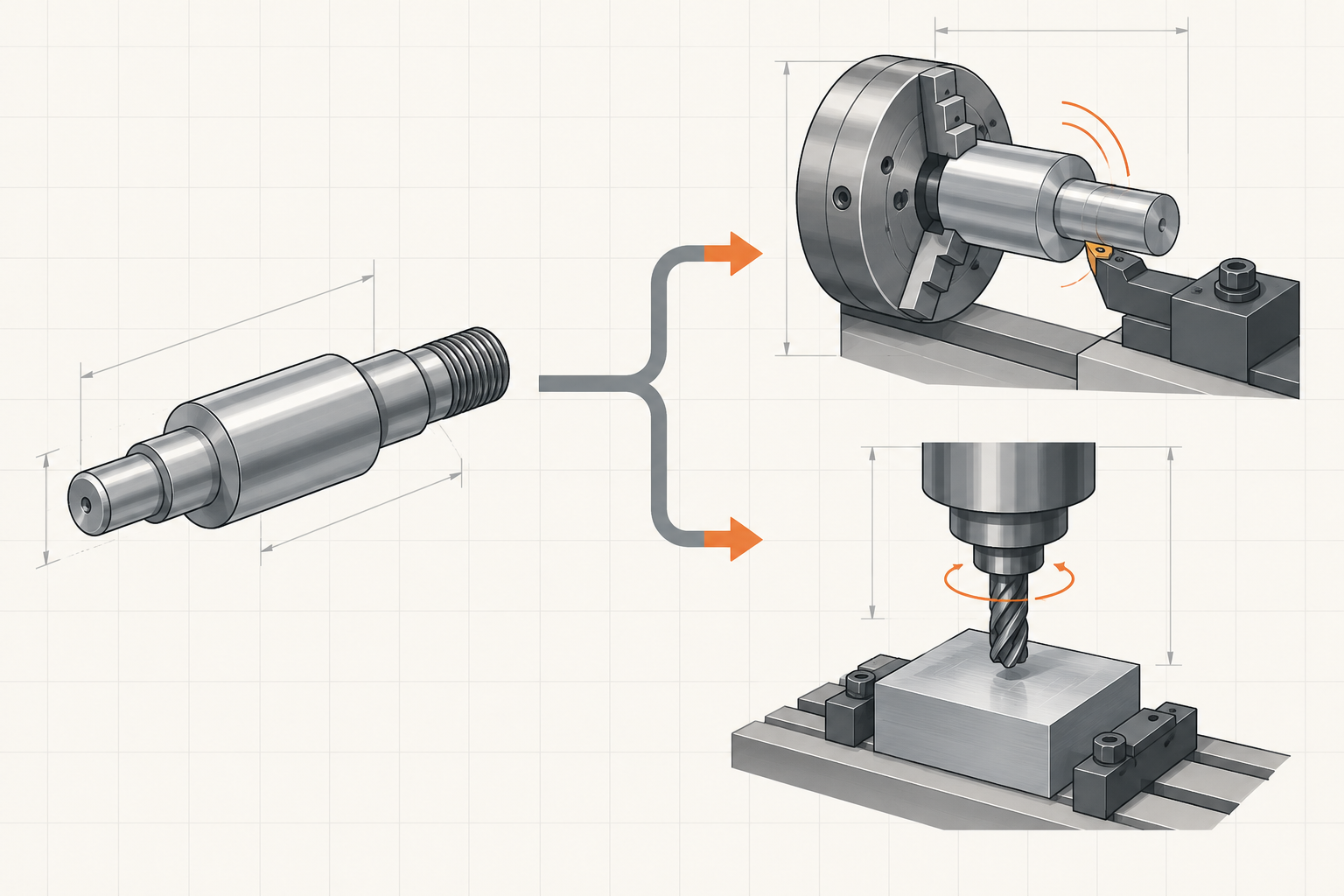
In one sentence: the main body is a body of revolution, the key tolerances are coaxiality or roundness, and batch consistency is required—if two of these three conditions are met, lathe machining is worth prioritizing. Conversely, if the main body is a plane or polyhedron, think milling or sheet metal first, and don't treat the lathe as a universal machine just to "save one process." For a specific part, the safest approach is still to give the drawing to the process side for a manufacturability assessment, to see how the workholding plan and tolerance chain should be arranged.
Frequently asked questions
The following questions are the ones most often asked after reading the previous content. The answers try to give the basis for judgment rather than empty talk.
What accuracy can lathe machining generally achieve?
The machining accuracy of modern CNC lathes usually falls in the micron-level range. The common industry expression is "micron level" rather than some fixed value. What can actually be achieved stably depends on the machine condition, workholding rigidity, tooling, material, cutting parameters, and inspection method, and also on which tolerance grade the drawing specifies. So the safer approach is: mark the key dimensions and tolerances clearly, and let the process evaluation confirm whether they can be met stably, rather than assuming a number first.
How do you choose between sliding headstock and fixed headstock lathes?
The common industry division is: for slender precision parts with smaller diameters (about 42 mm or less), larger length-to-diameter ratios, and high requirements for coaxiality and surface quality, sliding headstock machines are mostly used; for workpieces with larger diameters and shorter lengths, fixed headstock machines are mostly used. But this is only an empirical range, not a hard boundary. What really decides it is the part shape, material, batch size, tolerance requirements, and whether back-spindle machining is needed, with the final decision based on process evaluation and trial cutting results.
Can a lathe machine plastics?
Yes. Lathe machining is not limited to metals; plastics such as POM, PEEK, nylon, acrylic, and PTFE can all be turned. The cutting logic for plastics differs from that for metals: speeds are usually higher, feeds are lighter, tools are sharper, and attention must be paid to chip evacuation and clamping force—clamping too tightly can crush or deform the part, while clamping too loosely can cause slipping. Thin-walled plastic parts are especially prone to tool deflection and deformation, and often require soft jaws or special fixtures.
How do you choose between lathe machining and 3D printing?
It depends on the part shape and purpose. For rotationally symmetric parts (shafts, sleeves, discs, threaded parts) with requirements for dimensional accuracy, surface roughness, and material strength, lathe machining is usually the first choice; for prototypes with complex structures, internal channels or lightweight lattices, and no need for high strength, 3D printing is more suitable. The two are not opposed: a common approach is to first use 3D printing to verify the shape and assembly, then use a lathe for the final functional part.
What is the minimum batch size for lathe machining?
It can be done from a single piece to large batches. CNC lathes are program-controlled, so single pieces and small batches do not require additional tooling; changeover is mainly spent on programming, workholding, and first-article confirmation. The larger the batch, the less debugging time is spread over each piece. The specific minimum order quantity and cost structure depend on part complexity, material, tolerances, and surface requirements, and need to be evaluated from the drawing; this article does not give a uniform number.
Key takeaways
- The core of lathe machining is "the workpiece rotates, the tool moves," which is exactly the opposite of the milling machine's "the tool rotates, the workpiece moves." This determines that it is inherently suited to rotationally symmetric parts such as cylinders and cones.
- A lathe can do far more than turn external cylinders: internal bores, faces, threads, grooves, and parting off all count, and each operation corresponds to different tools and feed methods.
- Most modern lathe machining is now done on CNC lathes. Swiss-type is suitable for slender, small-diameter parts, while sliding-headstock type is suitable for larger-diameter short parts. Choosing the wrong type costs more money than choosing the wrong tool.
- The complete process is design → programming → setup and tool setting → cutting → inspection. Precision does not rely on the machine tool alone, but is accumulated step by step.



