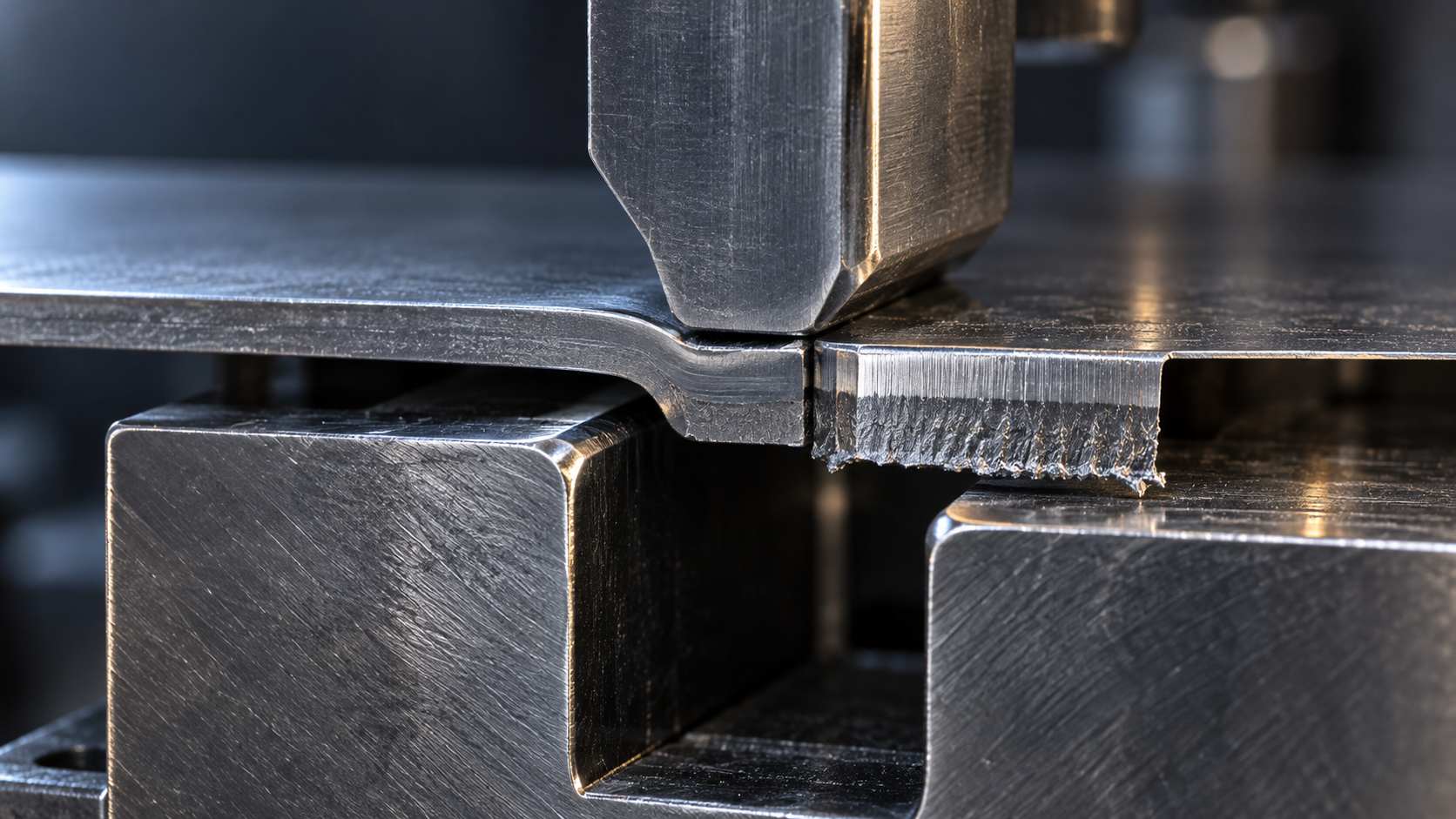
What Is Stamping Technology: First, Look Clearly at That One Cut When the Die Closes
Separation Processes and Forming Processes: The Two Main Lines of Stamping Technology
- Separation processes focus on cross-section quality and burrs: clearance, edge condition, and material condition are the main variables.
- Forming processes focus on springback, cracking, and wrinkling: fillet radius, blank holder force, and material elongation are the main variables.
- When the two types of processes are mixed, separation before forming is usually more stable, but holes near bends should be left to be pierced after bending.
How stamping is done: how many operations a sheet of material must go through
When stamping technology reaches the workshop, the first thing is not choosing the press tonnage, but arranging the process sequence. For the same sheet of material, whether to punch holes first or bend first, and at which step to leave the holes to be punched, directly determines the number of die sets, part precision, and scrap rate. If the process sequence is wrong, it cannot be made up later by adjusting the machine.
Separation and forming: the two main lines of process sequencing
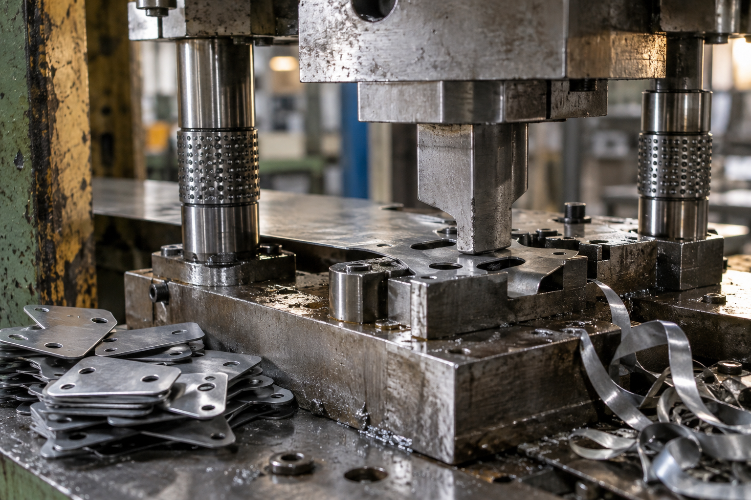
All stamping operations can be grouped into two categories. Separation operations cause the sheet material to break along a shear plane: cutting cuts coil or sheet material into strips or blanks, blanking punches out the outer contour of the part, piercing punches out inner holes, and cut-off separates the progressive strip from the part. Forming operations cause the sheet material to plastically deform without fracturing: bending forms an angle, drawing presses a flat sheet into a cup or box shape, flanging raises a ring of material at the hole edge or outer edge, and sizing performs final small corrections and flattening.
The principle for sequencing operations is very simple: first perform the operations that do not change the planar datum of the material, then perform the operations that change the datum. Blanking and piercing are completed in the flat state, where positioning is most accurate; once bending and drawing occur, the planar datum is destroyed. Therefore, the typical sequence for a bracket part is: blanking → piercing → bending → flanging → sizing. Only holes whose position would shift after bending, or whose hole edge would be consumed by the bend radius, are left to be punched separately after bending.
Single-station dies, compound dies, progressive dies: three ways of organizing dies
Single-station dies complete only one operation per stroke, and multiple operations are completed through multiple die sets or multiple setups. The die structure is simple and the tooling cost is low, making them suitable for small-batch prototyping and large, simply shaped parts, at the cost of labor and accumulated error between operations.
Compound dies complete blanking and piercing simultaneously in one stroke and at the same station, and the relative position of the inner and outer contours is ensured by the same die set, giving good hole-position accuracy. The disadvantage is that the die structure is compact and the wall thickness of the punch and die is limited; the part cannot be too small, and holes cannot be too close to the edge, otherwise the cutting edge strength is insufficient.
Progressive dies arrange multiple operations at multiple stations along a single strip, and each press stroke advances the strip by one pitch. Blanking, piercing, bending, and sizing can be completed continuously on one die, making them suitable for small parts with large batch sizes, complex shapes, and multiple forming steps. Their threshold lies in the die: pitch accuracy, pilot pins, strip rigidity, and scrap discharge—if any one of these is not made stable, problems begin to appear after a few hundred continuous strokes.
Returning to that bracket part: if the distance from the hole to the bend line is less than twice the material thickness plus the bend radius, the hole will be stretched and deformed during bending, and such holes must be scheduled after bending. Conversely, if the hole is only a mounting clearance hole and is not sensitive to deformation, punching it together at the blanking station saves one die set. The basis for judgment is not habit, but the hole position tolerance and bend radius on the drawing.
After arranging the process sequence, look back at the press tonnage and number of die sets, and the cost structure becomes clear: the more operations, the more dies, but the per-piece cycle time may be faster. When the batch is small, merging operations into a compound die or progressive die instead loses money on die cost; when the batch is large, the labor saved and the error between operations are the real gains.
Die clearance and sheared surface: the two numbers that determine burrs and cross-section quality
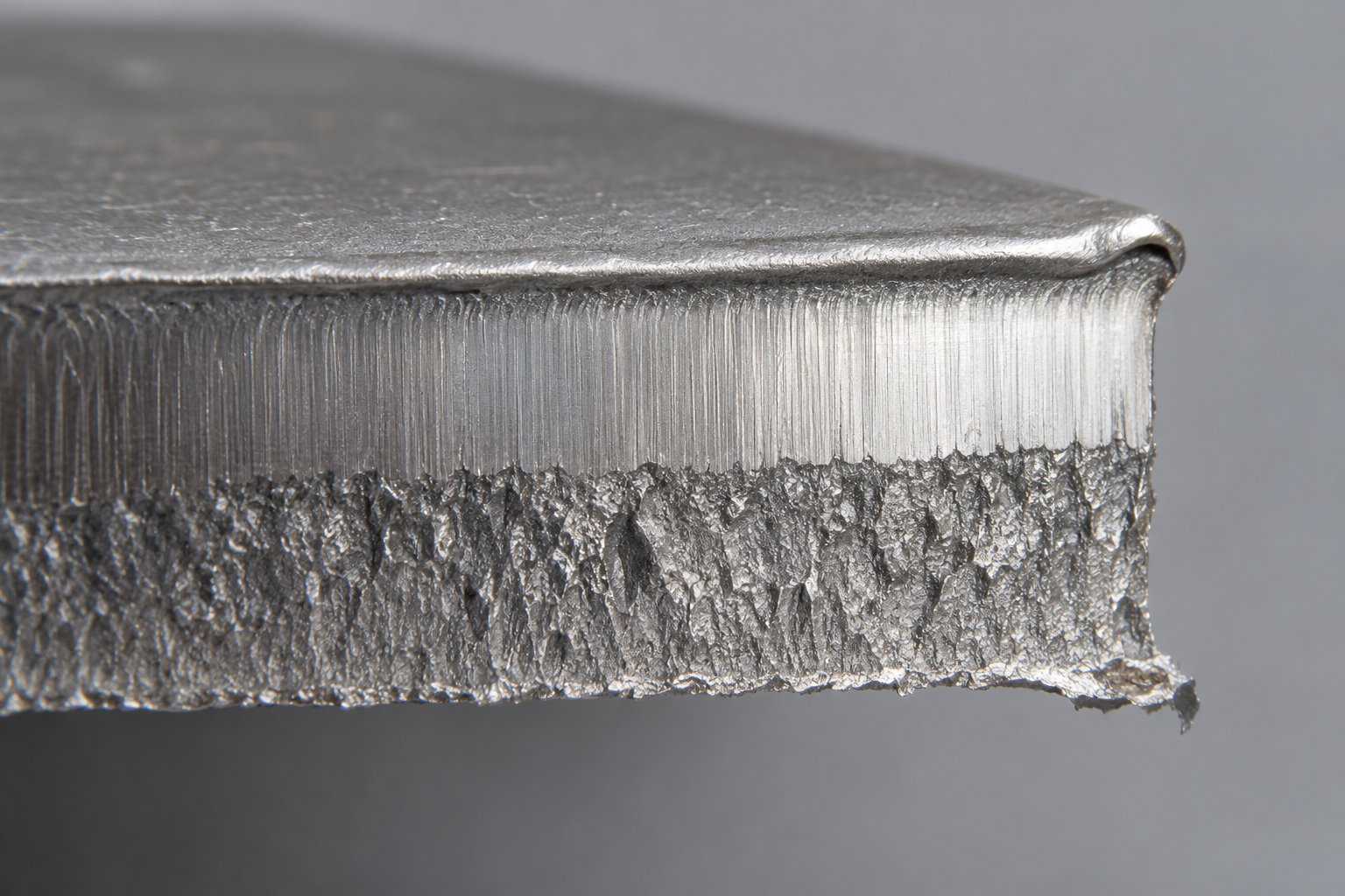
Four-zone structure of the sheared surface: understand the cross-section first, then adjust clearance
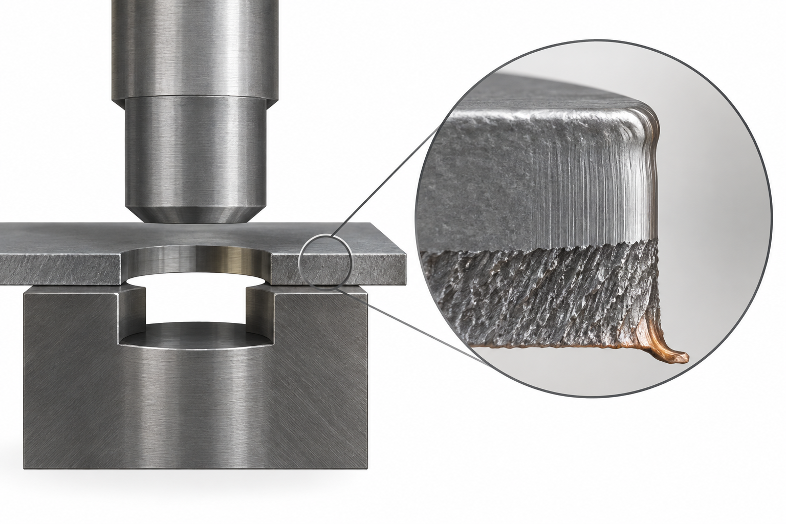
Clearance too small vs. too large: the two failure directions are different
- Burr height is usually accepted according to a percentage of stock thickness or an absolute upper limit; the specific value must be clearly written in the drawing or inspection specification, and it cannot be assumed that "it's fine after deburring."
- Edge radius is the lever for controlling rollover: after the edge becomes dull, rollover increases, and regular re-sharpening saves more than replacing the die afterward.
- For die steel selection, blanking dies commonly use cold-work die steels such as Cr12MoV and SKD11; for high-strength steel or high-volume applications, powder metallurgy high-speed steel may be considered, and the specific grade is evaluated by the stamping plant based on life.
- There is no unified promised value for re-sharpening life; it is strongly related to stock thickness, material strength, lubrication, and stroke count. The conventional approach is to set a stroke threshold or burr monitoring as the trigger condition for re-sharpening.
Bending and deep drawing: the two forming processes most prone to problems in stamping technology
Blanking determines the contour, while bending and deep drawing determine whether the part can be assembled. When these two processes have problems, it is often not that the die was made incorrectly, but that the material did not deform as expected. The difficulty in bending lies in springback and hole-position protection; the difficulty in deep drawing lies in the tug-of-war between cracking and wrinkling. These are discussed separately below.
Bending: springback, radius, and distance from hole to bend line
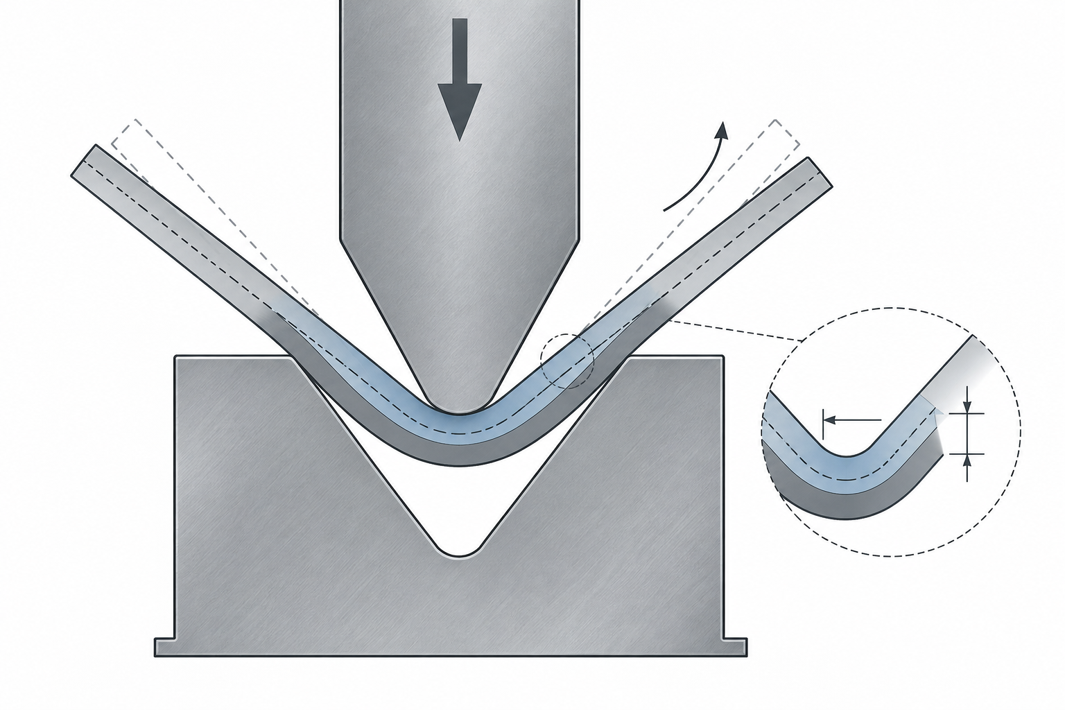
Bending is bending a flat sheet along a line into an angle. When the punch presses down, the inner side of the sheet is compressed and the outer side is stretched, while the neutral layer basically does not deform. After the punch lifts, elastic recovery makes the actual angle smaller than the die angle, and this difference is springback. The amount of springback increases as material strength increases: low-carbon steel is usually smaller, while stainless steel and aluminum alloy are more pronounced. Common industry practice is to apply angle compensation on the die, or add a sizing step after bending. The specific amount of compensation must be determined by trial based on measured values from the material batch.
Minimum bend radius is another hard constraint. If the radius is too small, the outer tensile strain exceeds the material elongation, microcracks appear directly, and the surface coating also breaks. Common industry empirical values: for cold-rolled low-carbon steel, the minimum inner radius is about equal to sheet thickness; for stainless steel, about 0.5–1 times sheet thickness; for aluminum and copper, there is considerable variation depending on grade, and confirmation is needed according to the drawing and material condition. Bend direction also matters: bending along the material rolling direction is more likely to crack than bending perpendicular to it, and this must be taken into account during nesting.
The distance from hole to bend line is often overlooked. If the hole is too close to the bend line, the hole will be stretched into an ellipse or even torn during bending. It is usually recommended to leave a distance of at least 1.5 times sheet thickness plus bend radius from the hole edge to the inner bend edge; if this is really not enough, bend first and then punch, or change the hole into a notch so the bend line passes through it. The bend direction (upward or downward) must be clearly marked on the drawing; otherwise the clamping and feeding direction will be reversed.
Deep drawing: blank holder force, drawing ratio, and the different causes of cracking and wrinkling
Deep drawing is drawing a flat blank into a die to form a cup or box shape. Unlike bending, deep drawing involves material in the entire flange region flowing into the die, and the amount of deformation is much greater. Two forces are contending: the punch pulls downward, while the blank holder presses the flange to prevent wrinkling. If the blank holder force is too small, the flange wrinkles; if the blank holder force is too large, the material cannot flow, and the wall is thinned or even cracked.
The draw ratio (the ratio of the blank diameter to the drawn part diameter) is the key to determining whether it can be drawn in one pass. A common industry reference: for low-carbon steel, the single-pass draw ratio is about 1.8–2.0; stainless steel and aluminum are lower, usually requiring two or more draws with intermediate annealing. If the die corner radius is too small, it will aggravate cracking; if too large, it will easily wrinkle. Generally, 5–10 times the sheet thickness is taken as the starting value. The punch corner also affects material flow and cannot be set arbitrarily.
The anisotropy of the material will cause ears to appear at the mouth of the drawn part—high in four directions and low in four directions. Deep-drawing steel controls the texture to reduce this difference. Lubrication is not optional in drawing; it directly reduces the friction between the flange and the die, allowing the material to flow; draw beads are used to control the local feed rate and prevent wrinkling from a section moving too fast. Among common materials, low-carbon steel and deep-drawing steel are the easiest to draw; stainless steel work-hardens quickly and requires greater tonnage and better lubrication; aluminum and copper have good elongation but tend to stick to the die.
Common criteria for both processes: first calculate the deformation, then determine the die
Bending and drawing seem like two different things, but the judgment logic is the same: first see whether the material can withstand this amount of deformation, then decide the die structure and the number of operations. Bending calculates the outer tensile strain and springback compensation; drawing calculates the draw ratio and the blank holder force window. Once both are calculated, then proceed to die design—this saves far more than opening the die first and then trial-and-error.
Materials and tolerances: the cost drivers in stamping processing technology
For the same drawing, changing the material or tightening the tolerance by one grade can make the die quote differ by a factor of two. In the cost structure of stamping processing technology, material and tolerance are the two most easily underestimated levers—they do not change the press, but they directly change the die steel grade, number of stations, sharpening frequency, and inspection fixture configuration.
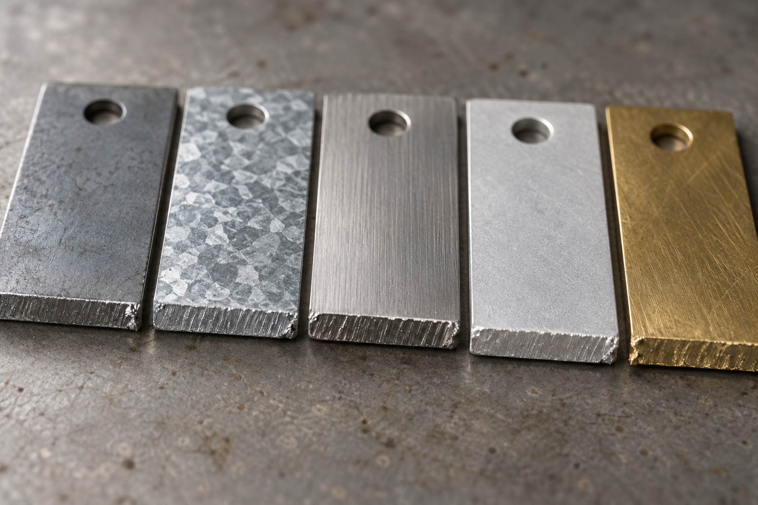
Performance differences of five common sheet metals in stamping processing technology
Cold-rolled low-carbon steel sheet (such as SPCC, DC01, etc.) is the easiest choice for stamping: moderate strength, high elongation, low springback, and it can cover blanking, piercing, bending, and shallow drawing. Galvanized sheet adds a zinc layer on this basis; during blanking, the zinc layer is dragged out by the shear surface, and zinc debris is more likely to be seen on the burr side. The die clearance usually needs to be slightly enlarged, otherwise the cutting edge will pick up debris. Stainless steel (304, 301, etc.) has high strength and work-hardens quickly, so the blanking force rises significantly, the cutting edge wears quickly, and springback is greater than that of low-carbon steel, so the bending radius must be made wider.
Aluminum sheet (5052, 6061, etc.) is soft, light, and conducts heat quickly. During blanking, it tends to stick to the tool and produces relatively large burrs, but it is very friendly for small-batch bent parts. Copper alloys (brass, phosphor bronze) have good elongation and excellent electrical and thermal conductivity, and are often used for connectors and terminals. The cost is a high material unit price and easily scratched surfaces, which places stricter requirements on feeding and die surface roughness. When selecting materials, ask two things first: what load the part bears, and how deep the forming process is. If the elongation is insufficient, even the best die cannot press out a qualified drawn part.
General range of achievable tolerances in stamping: reference values, not promises
The common stamping precision in the industry is roughly distributed as follows: the outer contour is generally on the order of ±0.1–0.2 mm, the punched hole diameter and hole position are mostly ±0.05–0.15 mm, the bending angle is commonly ±0.5°–1°, and flatness depends on sheet thickness and part size. Thin small parts can achieve the 0.1 mm level, while large parts will be looser. These numbers are references for judging whether a drawing is "easy to stamp," not guaranteed values from any factory—what can actually be achieved depends on material condition, die structure, equipment tonnage, and inspection fixture capability, and must be confirmed item by item according to the drawing and supplier.
The cost of tightening tolerances is not in the machining itself, but in the die and inspection fixtures. When hole position tolerance is tightened from ±0.15 to ±0.05, it often means adding pilot pins, improving template fit precision, and changing a single-station die to a progressive die; die costs and debugging cycles rise accordingly. If flatness is tightened to within 0.1 mm, it may require adding a sizing station or a leveling process. Inspection fixtures follow the same path: for outer shapes that calipers can check, switching to plug gauges, projectors, or even CMMs will include inspection labor and fixture costs in the unit price.
How to troubleshoot common defects: burrs, springback, cracking, wrinkling, and marks
In online machine adjustment for stamping processing technology, 80% of the time is spent on five words: burrs, springback, cracking, wrinkling, and marks. Their troubleshooting order should not be random trial and error, but should follow this chain: "first cutting edge and clearance, then material and lubrication, then die structure and blank holder force, and finally equipment and feeding." Below are executable adjustment directions one by one.
Burrs: measure clearance first, then check the cutting edge
When burrs become larger, the first step is to measure whether the unilateral clearance between the punch and die exceeds the common percentage range of material thickness (commonly 5%–10% in the industry; smaller for thin sheets and larger for thick sheets, to be confirmed according to the drawing and material). If the clearance is too large, it pushes the material toward the fracture zone, and burrs and rollover increase together; if the clearance is too small, the burnish zone becomes wider but the lateral force on the cutting edge rises, making chipping likely. If the clearance is normal, check whether the cutting edge is dull—when the cutting edge radius exceeds about 5% of the material thickness, it should be sharpened. Adjustment directions: repair the clearance, replace the cutting edge insert, or switch to a trimming process with negative clearance to press down burrs.
Springback: when the bend angle is off, adjust compensation first instead of forcing it
Bend springback is almost unavoidable in stamping processing technology. Low-carbon steel commonly shows 1°–3°, while stainless steel and high-strength sheet can reach 5°–8° (industry reference values; confirm actual values by material and R/t). Troubleshooting order: first confirm whether the material batch has changed and whether yield strength has increased; then check whether the bend radius matches the lower die V-groove (too small a V-groove increases springback); only last use angle compensation, negative springback, or a restriking station to remedy it. If springback suddenly drifts during a production run, it is most likely cumulative work hardening of the material or die temperature rise—don't rush to modify the die.
Cracking and wrinkling: two sides of deep drawing, with opposite causes
Deep drawing cracks and wrinkles are a pair of opposing effects. Cracking mostly occurs at the punch radius or sidewall, with root causes being insufficient material elongation, excessive draw ratio, too small a radius, excessive blank holder force, or insufficient lubrication. Wrinkling occurs at the flange or sidewall, with root causes being insufficient blank holder force, sheet that is too thin, or improperly set draw beads. Adjustment direction: for cracking, first reduce the draw ratio or increase the punch radius and improve lubrication; for wrinkling, first increase blank holder force or add draw beads. If both appear at the same time, it means the process window is already too narrow, and you should go back to the operation sequence and re-split the steps.
Indentations and inspection: gauges for first article and batch sampling
Indentations mostly come from foreign matter on the die surface, an uneven ejector plate, feeding scratches, or the coating on the material surface being scratched. During troubleshooting, first clean the die and check the ejector plate clearance, then check the feed guide rails and material rack. Inspection stage: for the first article, use calipers, plug gauges, and a projector to verify key dimensions and hole positions; check bend angles with an angle gauge or projection comparison; for batch production, sample inspect at the required frequency, and recheck flatness and geometric tolerances with a CMM or dedicated gauges. If the first article does not pass confirmation, do not start production—this is the most cost-saving discipline.
Once the troubleshooting order for the five defect categories above is fixed, adjusting stamping processing technology shifts from “finding it by trial” to “finding it by checking.” In the next section, we'll look at which parts should use stamping and which parts should switch processes.
Which parts are suitable for stamping processing technology, and which parts should switch processes
To judge whether a part should use stamping, first look at four variables: batch size, shape, material thickness, and precision. If even one of these four does not hold, forcing stamping will turn into a loss-making die investment.
Calculate batch size first: how many pieces the die cost must be spread over
The economics of stamping are typically “heavy upfront, light per piece.” For a simple die for blanking plus piercing, the common industry range is from several thousand to tens of thousands of yuan, and progressive dies or dies with deep drawing will be significantly higher. This money only makes sense when spread over the batch size.
The practical judgment is not “how many pieces are needed to open a die,” but “under the expected total volume, can the per-piece cost with a die beat alternative processes.” A rough industry dividing line: below several thousand pieces, and for flat parts that are not complex in structure, laser cutting plus bending is often more cost-effective; once you reach tens of thousands of pieces, stamping's per-piece cost advantage begins to show; above several hundred thousand pieces, stamping is almost the default option. This is only a reference magnitude; the specifics depend on part complexity and die structure, and need to be confirmed by drawing and supplier evaluation.
Next, shape: flat parts, symmetrical parts, and shallow drawn parts are most suitable
Stamping processing technology excels at two types of shapes. One is flat parts: brackets, shims, spring contacts, and connecting pieces, with an outer profile plus a few holes, which can be produced in one or two operations of blanking and piercing. The other is symmetrical formed parts: shallow drawn box bodies, cup-shaped parts, and flanged parts with flanging. As long as the draw ratio is within the material's allowable range, stamping's cycle time and consistency are hard to replace.
Conversely, several shapes should be considered for a process switch. For complex three-dimensional curved surfaces and parts with internal cavities and side undercuts, stamping requires multiple dies or cam structures, and both cost and risk are unfavorable; these usually go more directly to CNC machining. Plastic parts are not in the stamping category to begin with; once volume rises, they go to injection molding. For small-batch plastic parts in the prototype stage, using hand lay-up replica molding (vacuum casting) to make a few dozen pieces for structural verification is far more realistic than opening a steel mold.
Material thickness and precision: two thresholds that are often underestimated
In terms of material thickness, the common industry stamping sheet thickness range is roughly between 0.2–6 mm. Thin material (below 0.5 mm) is prone to wrinkling and feeding deviation, while thick material (above 3 mm) requires greater press tonnage and harder die steel, and the cutting edge wears faster. Beyond this range, it is not impossible to do, but the threshold for dies and equipment rises sharply.
On precision, two things must be distinguished: the dimensions stamping can stably achieve and the dimensions marked on the drawing are not necessarily the same thing. Outer profile, hole positions, and bend angles each have their own common tolerance bands. Hole positions are usually easier to make tight than the outer profile, while bend angles are looser because of springback. Once drawing tolerances exceed stamping's conventional capability, suppliers can only compensate by adding restriking operations or adding gauges, and the cost will jump directly.
Prototyping stage: don't rush to open a stamping die
Many projects get stuck here: the structure isn't frozen yet, but they're already thinking about opening a stamping die. A more reliable approach is to first use laser cutting for blanking, CNC bending, or a simple bending die to make a few sample parts, and verify the assembly relationships, hole positions, and bending sequence. At this stage, using sheet metal fabrication capabilities for small-batch trial assembly is low-cost and quick to modify.
Once the structure is finalized and the volume is confirmed, then invest in a hard stamping die. If the order is reversed, the cost of modifying a die once is often far more expensive than the time saved during the sample stage. To determine which path is suitable for the current stage, you can first look at the manufacturing capability overview, then decide whether to go with stamping, sheet metal, or CNC.
To sum up the above judgment in one sentence: if the volume is large enough, the shape is relatively flat or symmetrical, and the material thickness and precision are within conventional ranges, stamping processing technology is the right answer; if any one of these clearly goes beyond the limits, first consider sheet metal, CNC, injection molding, or handboard duplication, complete the structural verification, and then come back to evaluate the die.
From drawing to mass production: DFM checkpoints for stamping processing technology
The main cost of stamping processing technology lies in the die, not the individual part. Changing an edge distance or a radius on the drawing is usually much faster than changing it after the die has been made. Going through the following items before opening the die can save a round of trial runs and die modifications.
- Hole-to-edge distance: If the hole edge is too close to the material edge, the material edge will collapse or even tear during blanking. A common industry practice is that the hole-to-edge distance should be no less than the material thickness t, and important edges should be kept at 1.5t or more; confirm the specifics according to the drawing and supplier evaluation.
- Hole-to-bend-line distance: Holes on the inside of a bend will deform during bending. A common reference is that the hole edge should be at least 1.5t + the bend inside radius from the bend line; if this cannot be achieved, leave the hole to be punched after bending.
- Minimum bend radius: If the radius is too small, the outer fibers will crack. For low-carbon steel, the common inside radius can be around 0.5t, while stainless steel and hard aluminum require a larger radius; the material condition and supplier experience should be taken as the standard.
- Drawing depth and fillets: If the drawing depth exceeds what the material elongation can withstand, cracking will occur. Too-small punch fillets and die fillets will aggravate cracking and wrinkling; if necessary, draw in multiple stages.
- Material direction: Cold-rolled sheet has a rolling direction, and cracking is more likely when the bend line is parallel to the rolling direction. If the drawing does not specify this, confirm the direction with the supplier before opening the die.
- Whether tolerances are inspectable: If a tolerance is specified, there must be a corresponding measuring tool. Confirm before opening the die what measuring tools are used for hole positions, outer shape, bend angle, and flatness, and whether they can cover them; otherwise there will be disputes during mass production.
- Surface treatment requirements: Galvanizing, painting, and anodizing will change dimensions and burr conditions. Write into the drawing whether holes are punched and burrs are removed before or after treatment.
Among these points, hole-to-bend-line distance and minimum bend radius are the two most often overlooked. DFM for stamping processing technology is not about pushing tolerances down, but about exposing in advance the places that cannot be achieved by the process. Changing the relative position of a hole on the drawing is usually an order of magnitude cheaper than reworking the die. If you are truly unsure, mark the functional dimensions and appearance requirements clearly, and leave the rest to the supplier to determine according to process capability.
Common questions
The following questions basically all come from the judgment points that appear repeatedly above: clearance, springback, drawing ratio, tolerances, and process selection. The answers are given according to common industry practice, and the specific values still need to be confirmed according to the drawing, material condition, and supplier evaluation.
In stamping processing technology, what value should the blanking clearance actually be?
A common industry practice is to give it as a percentage of sheet thickness: for materials with good plasticity such as mild steel and aluminum, the double-sided clearance often falls within 8%–12% of sheet thickness; for stainless steel and hard materials, it is on the smaller side, about 6%–10%. If the clearance is too small, the bright band becomes wider and the cross-section looks better, but the cutting edge wears quickly and is prone to chipping; if the clearance is too large, burrs and collapse increase accordingly. The actual value depends on the material grade, sheet thickness, and cross-section requirements. It is best to mark the acceptable burr height on the drawing and let the die maker fine-tune it based on trial blanking results.
Why punch holes first and then bend, yet some holes are left to be punched after bending?
Punching first and then bending is the conventional sequence, because bending will cause hole positions to shift. But if a hole is too close to the bend line—the industry generally recommends that the distance from the hole edge to the inside edge of the bend be no less than the material thickness plus the bend radius, otherwise the hole will be stretched and deformed during bending—then this hole must be moved to be punched separately after bending. In progressive dies, it is more common to place such holes at the last station after the bending station, at the cost of an extra die station and higher cost.
How is springback in stamped parts controlled, and can it be adjusted in one go through the die?
Springback is the inevitable result of elastic recovery of the material, and it is very difficult to adjust it perfectly in one go. Common practices are overbending compensation (making the die angle slightly smaller than the target angle), adding negative angle or stiffening ribs, adjusting blank holder force, and if necessary switching to a material with less springback. Low carbon steel has small springback, stainless steel and high-strength steel have obvious springback, and aluminum is in between. After the first part comes out, measure the bend angle first, then decide the compensation amount; this is more practical than forcing tolerances on the drawing.
What precision can stamping processing technology achieve, and how much more expensive does tightening tolerances make it?
Common industry references: outer contour about ±0.1–0.3 mm, hole position about ±0.05–0.15 mm, bend angle about ±0.5°–1°, with specific values varying with material thickness and part size. These are ranges for judgment, not promises. Each time the tolerance is tightened by one grade, the workload for die edge precision, inspection fixtures, and first article verification will increase accordingly, and the cost increase is often not linear. Marking tolerances on the drawing that can be inspected and measured is more meaningful than marking a bunch of numbers that cannot be measured with calipers.
For small batch parts, should stamping, sheet metal, or CNC be used?
It depends on batch size and shape. For several thousand pieces or more, flat parts or symmetrical parts with shallow drawing, the unit cost of die stamping will drop significantly; for dozens to hundreds of pieces, laser cutting plus bending sheet metal is more cost-effective and also saves the die opening cycle. For complex three-dimensional structures, single pieces, or very small batches, CNC milling is more direct. In the prototyping stage, laser cutting or CNC is often used to verify the structure first, and after confirmation, it is transferred to stamping and die opening, which can push the risk of die rework to the front. For specific selection, you can judge by comparing the applicable scope of sheet metal capabilities and CNC machining capabilities.
Key takeaways
- Stamping uses dies and presses at room temperature to separate or form sheet metal; the core lies in process sequencing and die clearance.
- Blanking, piercing, bending, drawing, flanging, and sizing each have their own achievable precision and failure modes.
- Common defects (burrs, springback, drawing cracks, wrinkling) correspond to specific parameters such as clearance, fillet radius, and blank holder force.
- The economics of stamping are determined by production volume and die amortization; for small batches, sheet metal fabrication or CNC is often more cost-effective.
- Tolerances and material condition on the drawing must be confirmed before die making; many problems can be corrected at the DFM stage.



