
Geometric Principles of Wire EDM Taper Cutting: The Roles of the Upper and Lower Guide Nozzles and the Program Trajectory Plane
Suppose the set single-sided taper is 4°, but measurement after trial cutting shows 3.95°. This type of deviation does not necessarily indicate an error in the programmed angle. First, three positions must be distinguished: the program trajectory plane, the lower guide nozzle plane, and the upper guide nozzle plane. During straight cutting, the height differences among them are easily overlooked; in wire EDM taper cutting, however, they jointly determine the actual path of the electrode wire.
The electrode wire can be imagined as a diagonal line connecting the upper and lower guide nozzles. The lower guide nozzle is typically used as the reference for the X and Y directions, while the upper guide nozzle generates lateral displacement through the U/V axes, causing the electrode wire to incline relative to the workpiece. Generally, the greater the U/V movement, the greater the taper produced; however, which coordinate plane the displacement corresponds to and how the positive and negative directions are defined must be determined according to the specific machine control system.
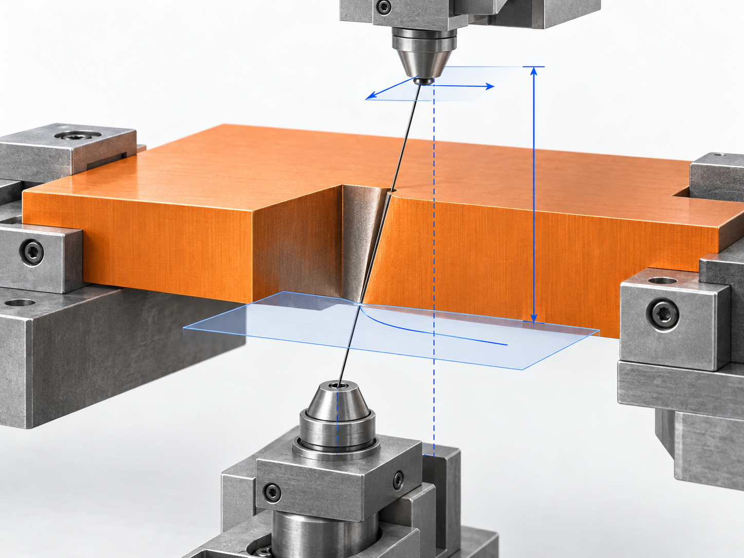
Therefore, the challenge of taper cutting is not simply entering an angle, but matching the coordinate compensation among planes at different heights. During subsequent trial cutting, the actual taper should be measured first, followed by correction of the program-plane dimensions: typically, ZSD is used to correct the angle first, and ZID is then used to correct the dimensions. Parameter names and algorithms are not universal across all wire EDM equipment, so numerical values must not be copied directly without referring to the machine manual.
Why Angular and Dimensional Deviations Occur in Wire EDM Taper Cutting
Suppose the set single-sided taper is 4°, but measurement after trial cutting shows 3.95°; at the same time, the required program-plane dimension is 6.000 mm, while the measured value is only 5.978 mm. These deviations do not necessarily mean that the program was calculated incorrectly. Common causes include failure to distinguish the angle definition, measurement reference, coordinate height, and machine condition. Wire EDM taper cutting requires distinguishing at least three objects: the program trajectory plane, the lower guide nozzle plane, and the upper guide nozzle plane. The height differences among these planes directly affect the lateral displacement of the electrode wire and the workpiece profile.
First Confirm the Single-Sided Taper Angle and Measurement Plane
The 4° shown on the drawing must first be confirmed as either the single-sided taper angle or the included angle between the upper and lower sides. During measurement, it must also be specified whether the part is a punch or a die, which side of the workpiece is being measured, and whether the dimension applies to the top surface, bottom surface, or program trajectory plane. If the total taper is treated as a single-sided angle, or if the measurement height differs from the programming height, the correction direction may be reversed even when the trigonometric calculation is correct.
ZSD, ZID, and Machine Condition Jointly Affect the Results
In some CNC wire EDM control systems, ZSD may be used to describe or correct the height and offset relationships associated with taper, while ZID may be involved in calculating the programmed-face dimensions or height differences, and Z0 is often related to the coordinate datum. However, these names, positive and negative directions, and algorithms must not be copied without reference to the specific controller. The actual workpiece thickness, the height from the wire guide nozzle to the table surface, wire verticality, tension, flushing, and discharge stability can all cause the set angle to differ from the measured angle.
Therefore, when troubleshooting, do not immediately adjust ZSD as soon as you see 3.95°. First determine whether the deviation is stable, whether the profiles at the upper and lower heights are consistent, and whether the wire-guiding system and electrode wire are in good condition. After confirming that the machine is basically stable, separate the issue into two tasks: correct the actual taper first, then correct the programmed-face dimensions. This is the only way to distinguish errors caused by geometric parameters from those caused by mechanical and discharge conditions.
Preparation for tapered wire EDM: establish the datum, correct verticality, and inspect the wire-guiding system
Trial-cut data from tapered wire EDM is only useful for correction when the machine condition is stable. Before starting, confirm that the workpiece is securely clamped and that the datum surface is flush with the table. Check whether the workpiece is warped, tilted, or deformed by clamping force. Then establish the datum and verify the program zero point, wire-threading position, and actual machining surface to avoid misidentifying zero-point or measurement-surface errors as taper-parameter errors.
First correct electrode-wire verticality for tapered wire EDM
Check the electrode-wire verticality according to the machine's existing calibration procedure. If the wire itself is already deflected, the upper and lower profiles may show dimensional errors in different directions even when the U/V offsets set in the program are correct. Also check whether the upper and lower wire guides or wire guide nozzles are aligned. Inspect for wear, contamination, looseness, and incorrect installation. Clean or replace abnormal components when necessary, but do not rush to modify ZSD or ZID while the condition of the wire-guiding system is unclear.
The electrode wire must also be selected to match the structure. A finer wire is generally advantageous for small internal radii or narrow slots, but cutting stability, speed, and suitability for the workpiece thickness require a trade-off; wire selection should not be based solely on the minimum slot width. After completing the clamping, datum, verticality, and wire-guiding system checks, cut a standard punch that is easy to measure. Only then are the resulting angle and programmed-face dimensions suitable for subsequent parameter correction.
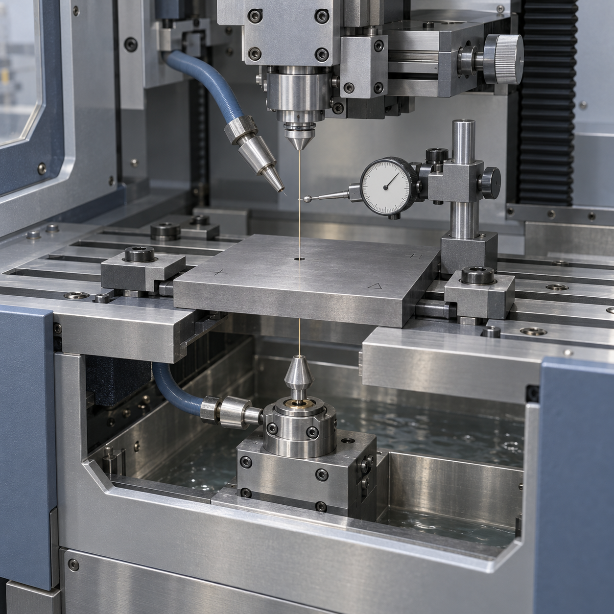
Core sequence for tapered wire EDM correction: use ZSD to correct the angle first, then ZID to correct the programmed-face dimensions
Do not modify multiple parameters simultaneously at the beginning of tapered wire EDM correction. A more reliable approach is to first trial-cut a standard punch with a simple shape and clearly defined measurement datums, then record the theoretical single-side taper, measured taper, theoretical programmed-face dimensions, and measured dimensions separately. This is the only way to determine whether the deviation comes from the angle or from the programmed-face dimensions.
First use ZSD to correct the actual taper
If the measured taper does not match the target value, first prioritize adjusting ZSD to bring the electrode-wire inclination back within the target range. The difference between the set angle and the measured angle must be evaluated together with the current taper direction, measurement surface, and the control system's definitions of positive and negative values. Do not infer the direction solely from whether the parameter should be increased or decreased. Make only small adjustments each time, then recut and remeasure the angle.
Then use ZID to correct the programmed-face dimensions
When the measured angle is already close to the target, check the dimensions on the programmed trajectory surface. If the angle is acceptable but the dimensions still deviate, use ZID to correct the programmed-face dimensions. Note that ZID may be involved in the system's height-relationship calculations; after adjustment, the upper and lower coordinate conditions may change accordingly. If the control system requires the total height to remain unchanged, reverse compensation of ZSD is usually also required. The specific relationship must be confirmed in the machine manual.
Tapered wire EDM correction formulas and calculation example: deriving the adjustment from measured values
Before calculating tapered wire EDM correction, first confirm the angle definition. In the following text, β denotes the single-side taper angle, not the included angle between the upper and lower profiles. During measurement, also confirm the punch or die orientation, the measurement height, and which programmed trajectory surface the dimensions belong to. If a height difference is expressed as c = ZID × tanβ, β must be entered in angular units, and c and ZID must use the same length units. However, ZID may correspond to different effective heights or coordinate relationships in different control systems, so the names and positive/negative directions of ZSD, ZID, and Z0 must not be applied directly without consulting the machine manual.
For tapered wire EDM correction, check the angle first, then the programmed-face dimensions
For example, the workpiece thickness is approximately 30.08 mm, the theoretical single-side taper is 4°, and the programmed-face dimension is 6.000 mm. After trial cutting, the measured taper is approximately 3.95° and the programmed-face dimension is approximately 5.978 mm. At this point, do not make large adjustments to both parameters simultaneously: first compare the theoretical and measured angles, and use ZSD to correct the taper. A measured angle that is smaller usually indicates insufficient effective lateral offset, but the specific increase or decrease direction must be confirmed based on the current taper direction and the controller's definitions. The significance of the formula on the machine is to relate the height difference to the lateral offset of the wire-guiding system, not to provide universal input values for every machine.
Recut verification after tapered wire EDM correction
After adjustment, the part must be retested under the same clamping conditions, wire-threading direction, and measurement datum. If the angle improves but the program-plane dimensions deviate again, first check the coupling between ZID and ZSD. If the recutting results fluctuate significantly, first investigate electrode-wire perpendicularity, guide alignment, tension, and flushing conditions. The data above are only intended to demonstrate the “measure–calculate–correct–recut” method; they are not universal setting values.
Wire EDM taper machining for upper and lower irregular profiles and round-top square-bottom transitions: first confirm the profiles and check for interference
A conventional single taper can usually be described by one continuous angle, but parts with irregular upper and lower profiles, round-top square-bottom transitions, or programming based on the upper surface do not follow this rule. In such cases, the object of wire EDM taper machining is not merely to “tilt an electrode wire,” but to control the upper profile, lower profile, and trajectories at different heights simultaneously. A conventional single-taper formula cannot be applied directly to all irregularly shaped parts.
Wire EDM taper machining: first confirm the upper and lower profiles and the programming plane
Before programming, refer back to the drawing: confirm the upper profile, lower profile, workpiece thickness, and the programming plane to which the dimensions refer. Also clarify whether the angle is a single-side taper or total taper, and whether the part is a punch or a die; otherwise, the measurement and correction directions may be reversed. If the control system supports programming for irregular upper and lower profiles, input the profiles, datum heights, and wire-threading path separately according to its definitions. Do not simply modify one taper angle.
Simulate the dry run and check the wire EDM taper path for interference
Before actual sparking, perform a simulated dry run to verify the projected relationship between the upper and lower profiles and observe whether the electrode wire moves continuously at corners, narrow slots, and internal radii. Pay particular attention to interference between the electrode wire and the workpiece, fixture, and upper and lower wire-guide components, and confirm the wire-threading position and wire-retraction path. If the path appears correct on both the upper and lower surfaces but the wire collides at an intermediate height, this usually indicates that the height datum, profile correspondence, or the control system’s interpolation definition still needs to be reviewed. After confirming everything is correct, proceed with a trial cut. During measurement, also record the actual measurement surface to avoid misidentifying geometric errors as ZSD/ZID parameter errors.
When wire EDM taper machining is inaccurate, causes wire breaks, or produces unstable surfaces, which process factors should be checked first?
When angular deviation occurs during wire EDM taper machining, do not immediately modify ZSD or ZID. If the angle measured from the same program differs each time, or if the taper changes along the workpiece height, the problem may originate in the wire-guide system, perpendicularity, or discharge conditions rather than in the geometric parameters themselves. The correct sequence is to check the machine condition first, then use stable trial-cut data to correct the parameters.
For wire EDM taper machining, first check the wire-guide system and electrode-wire perpendicularity
Separate discharge factors from parameter errors in wire EDM taper machining
Higher discharge energy generally helps increase the removal rate, but it may produce a rougher surface and unstable discharge. Lower energy generally benefits surface quality, but may sacrifice cutting speed. The specific settings must be verified according to the material, thickness, and machine model; parameters from another machine must not be copied directly. After eliminating obvious faults, perform another standard trial cut and record the theoretical angle, measured angle, theoretical program-plane dimensions, measured dimensions, original ZSD, original ZID, correction direction, and recutting results. Only if the error converges after recutting can the correction direction be considered effective. If the angle and dimensions drift simultaneously, continue checking the mechanical and discharge conditions instead of making a large one-time adjustment to multiple parameters.
Common questions about wire EDM taper machining
Corrections in wire EDM taper machining cannot be separated from the specific machine tool, control system, and measurement datum. The following section addresses common questions about ZSD, ZID, trial-cut corrections, and machining parts with irregular upper and lower profiles.
Are ZSD and ZID applicable to all wire EDM equipment?
Not necessarily. ZSD and ZID are parameter names used in this article to explain the relationship between taper and height. Their specific meanings, positive and negative directions, and calculation methods may vary between machine tools and control systems. Before actual programming, consult the machine manual and do not directly copy values from another machine model.
Can angle correction and program-plane dimensional correction be performed at the same time?
It is not recommended to make large adjustments to both at once. Usually, first use a trial cut and ZSD to bring the measured taper close to the target, then use ZID to correct the program-plane dimensions. If adjusting ZID changes the height relationship, ZSD must also be compensated in the opposite direction according to the control system’s definition. Finally, perform a recut for confirmation.
If the single-side taper is set to 4° but the measured value is only 3.95°, what should be checked first?
First confirm whether the measurement is a single-side angle or total taper, and verify the measurement height, programming plane, and punch or die orientation. Then check electrode-wire perpendicularity, upper and lower wire-guide alignment, tension, flushing, and discharge stability. Once the machine condition is confirmed to be normal, correct ZSD according to the single-variable principle.
Can the standard taper formula be applied directly when the upper and lower profiles are different, or when the top is round and the bottom is square?
Generally, it cannot be applied directly. First confirm the upper and lower profiles, programming plane, workpiece thickness, wire-threading path, and the programming methods supported by the control system. Then simulate a dry run and check for interference with the workpiece, fixtures, and wire-guiding components. The standard single-taper formula can only serve as a reference for specific geometric relationships.
Key takeaways
- The essence of wire EDM taper cutting is the lateral displacement of the electrode wire between the upper and lower guide nozzles. The U/V movement and effective height jointly determine the degree of inclination.
- The program trajectory plane, lower guide nozzle plane, and upper guide nozzle plane must be understood separately; the coordinate relationships used for straight cutting cannot be applied directly to taper cutting.
- On-machine correction should follow the sequence of “correcting the actual taper first, then correcting the program-plane dimensions,” while accounting for the coupling between ZSD and ZID.
- Before adjusting parameters, first check the electrode-wire perpendicularity, guide alignment, tension, flushing, and discharge stability to avoid misdiagnosing machine-condition issues as geometric parameter errors.



