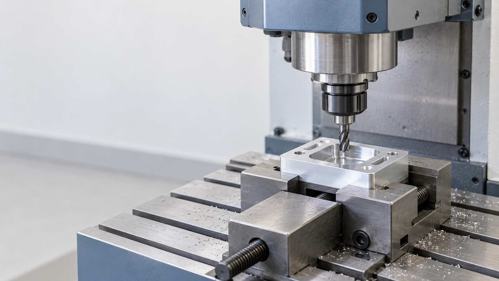
What to Check First When Selecting a CNC Milling Machine: Start with Part Geometry, Dimensions, Tolerances, and Fixturing
CNC milling machine selection should not start with the number of axes or the maximum spindle speed. Instead, it should first answer a delivery question: Can the machine consistently complete the target part under the agreed material, fixturing, tooling, and measurement conditions? Positioning accuracy, spindle speed, and effective travel listed in a specification sheet represent the machine’s capabilities only under specific conditions; they do not equal the final part tolerances achievable with all materials and processes.
The first step is to break down the part requirements. Confirm the maximum envelope dimensions, blank size, and weight, then identify critical datums, hole locations, pockets, slots, inclined surfaces, curved surfaces, minimum radii, tolerance zones, and surface roughness requirements. Planes, steps, holes, and one-directional pockets can generally be evaluated initially using a three-axis process. If the part has multiple datum faces, deep pockets, angled holes, or complex curved surfaces, continue by checking tool accessibility, the number of fixturing operations, and rotary-axis requirements.
Build a Selection Chain Based on “Part Requirements—Equipment Capabilities—Verification Methods”
- Part requirements: Record geometric features, material, dimensions, tolerances, surface requirements, production volume, and delivery objectives.
- Equipment capabilities: Verify effective X/Y/Z travel, worktable dimensions, load capacity, spindle and tool holder, tool magazine, coolant and chip evacuation, and inspection configuration.
- Verification methods: Define the fixturing sketch, tool orientations, interference checks, test cuts, and dimensional reports in advance rather than simply accepting the equipment’s advertised specifications.
In particular, note that fitting the workpiece envelope on the worktable does not necessarily mean the part can be machined. Fixtures, locating blocks, tool extension, clearance at the spindle nose, and the chip evacuation direction all reduce the actual machining envelope. Proper CNC milling machine selection should ultimately return to whether the target part can be machined, measured, and reproduced consistently, rather than focusing solely on the equipment label.
How to Choose Between Three-, Four-, and Five-Axis CNC Milling Machines: Judge by Machining Features
The choice between three-, four-, and five-axis CNC milling machines should not begin with the number of axes or the maximum spindle speed. Instead, first consider the directions from which the part needs to be machined, whether the datums can be converted consistently, and whether the critical surfaces require continuous adjustment of the tool orientation. More axes do not automatically mean higher accuracy; rotary-axis calibration, programming quality, fixture rigidity, tool extension, thermal stability, and operator capability all affect the final part result.
| Equipment type | More suitable machining features | Key points to confirm when purchasing |
|---|---|---|
| Three-axis CNC milling machine | Planes, steps, holes, slots, basic contours, and cavities accessible from a single direction | Tool accessibility, fixturing datums, deep-cavity internal corners, and measurement plans for critical holes |
| Four-axis CNC milling machine | Side features, circumferential hole patterns, and multi-face features requiring indexing or rotary machining | Rotary-axis load capacity, positioning accuracy, fixture interference, and datum relationships after indexing |
| Five-axis CNC milling machine | Angled holes, complex surfaces, deep cavities, continuous multi-face machining, and parts requiring fewer datum changes | Rotary-axis swivel angle, tool orientation, spindle-to-fixture interference, post-processing, and test-cut validation |
Three-axis CNC milling machines: simple geometry does not mean low requirements
If most of a part’s features can be machined from one direction, a three-axis CNC milling machine generally makes it easier to establish stable fixturing and inspection datums. It can also complete side or back features through multiple setups, but each repositioning introduces the risk of datum changes. For parts with tight tolerances on planes, hole locations, and cavities, first evaluate inspection fixtures, locating pins, alignment methods, and test-piece results rather than judging solely by the number of machine axes.
Five-axis CNC milling machines: fewer setups do not automatically mean higher accuracy
The primary value of a five-axis CNC milling machine is improved access to multiple faces, continuous adjustment of tool orientation, and fewer certain types of re-fixturing. This makes five-axis machining particularly worth evaluating for complex surfaces, angled holes, and deep cavities. However, rotary-axis errors, tool center point control, fixture rigidity, and programming strategy still require validation. The final choice should return to the delivery objective: under the specified material, fixturing, tooling, and measurement conditions, which machine can consistently reproduce the critical dimensions and geometric tolerances?
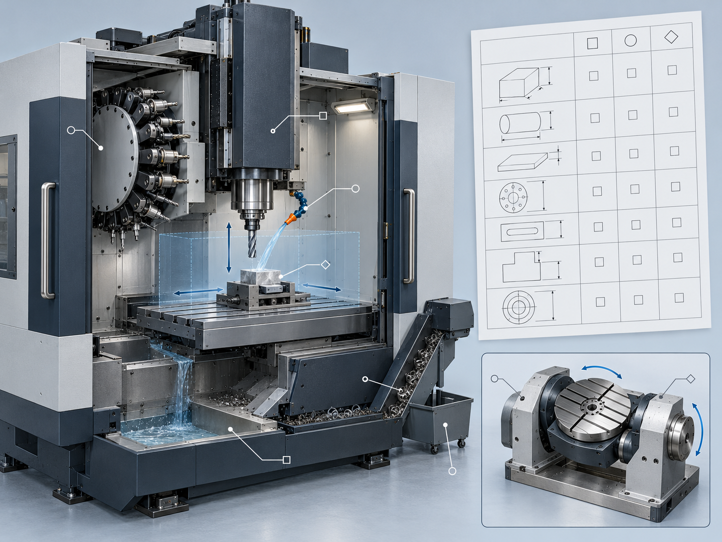
CNC milling machine capability evaluation table: travel, load capacity, spindle, tool holder, tool magazine, and inspection
A CNC milling machine’s specification sheet should not be evaluated solely by maximum spindle speed or positioning accuracy. During purchasing, part requirements, machine capabilities, and validation methods should be checked together in the same table. Effective travel must account for the fixture, locating blocks, and safety clearances; table load capacity depends not only on the blank’s weight but also on the fixture, rotary components, and cutting loads. Spindle power, speed, and tool-holder interface determine the applicable tool size, extension length, and material cutting range.
| Part requirements | Key CNC milling machine capabilities to verify | Recommended verification method |
|---|---|---|
| Maximum envelope dimensions and fixturing space | X/Y/Z effective travels, worktable dimensions, and spindle-nose clearance | Perform a spatial check using the blank, fixture, and tool models |
| Blank and fixture weight | Maximum worktable load, support positions, and rotary-axis load | Verify against the equipment manual and the total mass after fixturing |
| Deep cavities, narrow slots, and small radii | Spindle speed/power, toolholder interface, tool magazine capacity, and tool overhang limitations | Perform reachability and interference checks using the target tools |
| Multiple-sided datums and inclined holes | Rotary-axis range, rotary accuracy, and fixture interference clearance | Check the tool-axis direction and measurement datums in each orientation |
| Critical hole locations and dimensions | Positioning accuracy, repeatability, spindle runout, and in-process inspection configuration | Confirm through trial-cut parts, hole-location measurements, and inspection records |
| Continuous cutting and batch stability | Coolant method, chip evacuation capability, tool magazine capacity, and tool-change logic | Observe the trial-cutting process, chip breaking, built-up edge, and tool-change abnormalities |
Public equipment pages commonly use this format of listing parameters in a consolidated manner. For example, a three-axis machine may list X/Y/Z travels of 600/500/300 mm, a 650×650 mm worktable, a maximum load of 300 kg, a 20,000 rpm spindle, and an HSK-A50 toolholder; a five-axis machine may list linear travels of 450/680/400 mm, a 400 mm worktable, a 150 kg load capacity, and A/C-axis rotary ranges. These are example data for individual machines only, not industry-wide standards or parameters of Agile-X's own equipment. Actual machine selection still requires the supplier to confirm each item based on the part's 3D model, blank, fixturing plan, and acceptance requirements.
Why sufficient work travel may still be inadequate for machining: tool accessibility and fixture interference
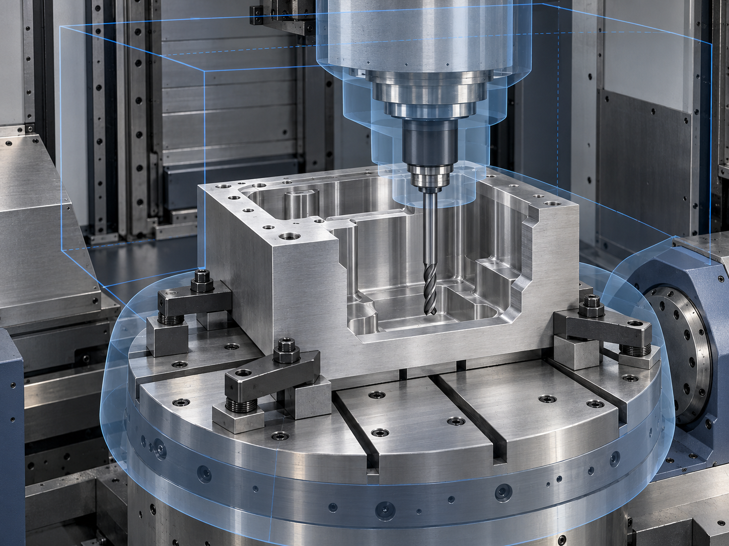
The effective travel of a CNC milling machine is only the first boundary. The fact that a part's outer profile fits within the work area does not mean the tool can reach every feature. The fixture baseplate, locating blocks, clamps, and spacers occupy space; after the blank is clamped, the highest point must also clear the spindle nose, tool magazine, and machine guarding. During procurement, verify the actual envelope in the clamped condition rather than simply comparing the drawing's outer dimensions with the X/Y/Z travel.
Tool accessibility on a CNC milling machine is limited by deep cavities and internal corners
Deep cavities, narrow slots, and small internal corners are often more likely to become limiting factors than the part's maximum dimensions. Tool diameter determines the minimum slot width and internal corner radius, tool overhang affects rigidity and vibration, and the distance from the spindle nose to the workpiece surface determines whether the required depth is genuinely machinable. Even when the machine has sufficient travel, an excessively long tool may deflect, chatter, or evacuate chips poorly, ultimately affecting dimensions and surface roughness.
CNC milling machines must also be checked for rotary-axis, fixture, and chip-evacuation interference
When using a four- or five-axis CNC milling machine, also verify the rotary-axis swivel angle, table diameter, workpiece weight, and fixture envelope. After rotating to a particular orientation, the fixture may collide with the column, spindle, or enclosure; eccentrically clamped workpieces may also exceed the rotary axis's allowable load. If chips generated during deep-cavity machining cannot be evacuated smoothly, they may cause recutting and accelerated tool wear.
- Provide the 3D part model, blank dimensions and weight, and a complete workholding sketch.
- Require the supplier to specify the tool diameter, tool overhang, and tool orientation for critical features.
- Perform interference checks among the spindle, fixture, rotary axis, and workpiece for multi-face machining.
- Confirm the inspection plan for deep cavities, critical hole locations, and datum surfaces in advance to avoid being unable to inspect the part effectively after machining is complete.
What to check when accepting CNC milling machine accuracy: geometric accuracy, positioning accuracy, and repeatability
Acceptance of a CNC milling machine cannot be based on a single positioning-accuracy figure. A complete assessment should include at least four levels: machine-tool geometric accuracy; linear-axis positioning and repeatability; spindle and rotary-axis condition; and the dimensional and geometric results of a trial-cut part. The first two levels describe the machine's motion and structural condition, while the latter two more closely reflect its ability to deliver actual parts.
Check CNC milling machine geometric accuracy and motion accuracy separately
Geometric checks may include table flatness, perpendicularity between linear axes, radial runout of the spindle bore, the relationship between the spindle axis and table surface, and relevant runout of the rotary axis. Positioning-accuracy testing should clearly define the measurement travel, target positions, point distribution, and approach direction. Points typically need to be distributed evenly along the commonly used or contractually specified travel, with target positions approached separately from the positive and negative directions. The machine should also be warmed up before measurement so that its condition is comparable.
| Acceptance levels | Key Inspection Items | Conclusions That Cannot Be Drawn Directly |
|---|---|---|
| Geometric Accuracy | Flatness, perpendicularity, spindle runout, and axis relationships | Cannot Be Directly Equated with Finished-Part Dimensional Tolerances |
| Linear-Axis Motion | Positioning accuracy, repeatability, and bidirectional error | Cannot Cover All Materials and Cutting Conditions |
| Spindle and Rotary Axes | Runout, rotary positioning, and rotary-axis condition | Cannot Replace Tool Orientation and Interference Verification |
| Test Piece | Dimensions, geometric tolerances, surface quality, and report records | Cannot Represent All Parts and Batch Stability |
CNC Milling Machine Positioning Accuracy Does Not Equal Part Tolerance
The machine tool's nominal positioning accuracy is a motion performance indicator obtained under specific measurement conditions. It is not equivalent to the final dimensional accuracy achieved with a particular material, tool, workholding setup, and thermal condition. When GB/T 17421.2-2023 or ISO 230-2 is involved, the official standard, contract terms, and inspection plan shall prevail. The environmental conditions, warm-up status, coordinate datum, measuring instruments, number of repetitions, and permissible deviations must also be clearly specified. At the final acceptance stage, an agreed test piece should additionally be machined to verify critical dimensions, geometric tolerances, and measurement reports, rather than using a single reading or one set of laser data as a substitute for a complete assessment.
How to Organize On-Site Acceptance: Warm-Up, Measurement Paths, Bidirectional Approach, and Test-Piece Verification
Acceptance of a CNC milling machine should not begin with “measuring one accuracy value on site.” Instead, the acceptance scope, equipment condition, and evaluation method should first be specified in the contract. At a minimum, the warm-up or thermal-stabilization conditions, ambient temperature, coordinate system, measuring instruments, measurement points, bidirectional approach method, number of repetitions, permissible deviations, and handling of nonconformities must be clearly defined. Otherwise, even if the positioning accuracy in the report appears to meet requirements, it is difficult to determine whether it can be translated into the machining capability required for the target part.
- Warm up the machine and confirm its condition.Operate the equipment as specified in the contract so that the spindle, linear axes, and control system reach the specified or agreed stable condition. Record the warm-up time, environmental conditions, equipment alarms, and the condition of the tools and fixtures. A single reading taken with the machine cold cannot be used directly as the final conclusion.
- Check geometric accuracy first.Check the flatness of the worktable, the perpendicularity between the linear axes, the radial circular runout of the spindle bore, and the relationships between the spindle axis, worktable surface, and linear axes. For CNC milling machines equipped with rotary axes, also verify the runout, rotary condition, and positioning performance of the relevant axes.
- Re-measure the positioning and repeatability of the linear axes. The measurement points should cover the commonly used working travel or the travel specified in the contract, and should be distributed as evenly as possible along the travel. Each target position should be approached from both the positive and negative directions as agreed, in order to identify backlash, servo errors, and differences in mechanical transmission. The measurement axis should also be as close as possible to the functional point of the axis under inspection to reduce Abbe and lever-arm errors.
- Finally, perform verification with a test piece. Machine the test piece using the agreed material, blank dimensions, tooling, and fixturing method, and inspect critical dimensions, geometric tolerances, hole-position relationships, surface roughness, and repeat machining results. The acceptance report should include measurement data, instrument information, and the basis for acceptance, rather than retaining only a laser measurement summary.
GB/T 17421.2-2023 or ISO 230-2 may be used as a reference framework for the relevant inspections, but the specific scope of application, measurement methods, and permissible deviations shall remain subject to the applicable official standards, purchase contract, and inspection plan. Machine tool geometric accuracy, axis motion accuracy, and test-piece dimensional accuracy belong to different levels and must be recorded and evaluated separately.
Writing CNC Milling Machine Parameters into the Procurement Specification: From Equipment Capability to Part Delivery
The ultimate criterion for selecting a CNC milling machine is not maximum spindle speed, the number of axes, or a single positioning-accuracy specification, but whether the machine can reliably complete the target part under the agreed material, fixturing, tooling, and measurement conditions. The procurement specification should translate “equipment parameters” into executable part-delivery requirements and leave traceable records for subsequent acceptance.
What Part Information Should Be Included with a CNC Milling Machine Procurement Specification?
- Part drawings, material grades, blank dimensions and weight, as well as critical datums and fixturing orientation.
- Critical dimensions, tolerance grades, geometric requirements, surface roughness, and the method for judging appearance.
- The anticipated fixturing scheme, datum-conversion requirements, and tool accessibility for critical features such as deep cavities and narrow slots.
- Test-piece material, machining features, sampled dimensions, inspection equipment, and report format.
On the equipment side, the specification should state item by item the effective X/Y/Z travels, worktable dimensions and load capacity, spindle speed and power, tool-holder interface, tool magazine capacity, coolant and chip-removal conditions, rotary-axis range, and the measurement conditions for positioning accuracy and repeatability. If the machine is equipped with in-process inspection, the inspection targets, correction logic, and data-output method must also be specified. Nominal positioning accuracy cannot be directly rewritten as a “finished-part dimensional guarantee”; part accuracy is also affected by thermal stability, tool wear, fixture rigidity, programming, and material deformation.
Rewriting Equipment Parameters as Acceptable Criteria
The contract should clearly specify the warm-up or stabilized state, environmental conditions, coordinate datum, measuring instruments, measurement points and directions, number of repetitions, permissible deviations, and handling of nonconformities. Comparisons of linear-axis positioning accuracy should state whether the measurement covers the full travel or the contractually specified travel, and whether approaches are made from both the positive and negative directions. Equipment acceptance should also incorporate geometric accuracy, spindle or rotary-axis condition, and test-piece results; a single inspection report covering only one parameter is not sufficient.
Common Questions About CNC Milling Machine Selection and Acceptance
CNC milling machine selection cannot be based solely on the number of axes, maximum spindle speed, or a single positioning-accuracy specification. Part geometry, the fixturing scheme, tool accessibility, material, tolerances, and acceptance conditions should be evaluated together as part of one decision chain.
Is a Three-Axis CNC Milling Machine Sufficient for Machining Precision Parts?
Usually, yes. Three-axis CNC milling machines can often handle planes, holes, slots, steps, basic profiles, and cavities oriented in a single direction. If the part includes angled holes, features distributed around multiple faces, deep cavities, or complex surfaces, four-axis, five-axis, or specialized fixturing solutions require further evaluation. The final result also depends on the material, tooling, fixtures, thermal stability, and inspection method.
Is a Five-Axis CNC Milling Machine Necessarily More Accurate Than a Three-Axis Machine?
Not necessarily. The primary value of five-axis machining is improved access to multiple faces, tool orientation adjustment, and reduced re-fixturing; it does not automatically mean higher part accuracy. Rotary-axis calibration, synchronized-motion errors, programming, fixture rigidity, tool condition, and the measurement plan can all affect the results. Acceptance should be based on test cuts and the agreed acceptance data.
If the machine's working envelope is large enough, why is interference checking still necessary?
The working envelope only indicates the range of the machine's linear motion. Fixtures, locating blocks, blank height, tool diameter, tool stick-out, distance from the spindle nose, rotary-axis swivel angle, and chip evacuation space may all limit machining. Before purchasing, the 3D model, blank dimensions, and fixturing sketch should be reviewed together to verify critical tool orientations and fixture clearances.
If the contract does not clearly specify the measurement conditions, how should the acceptance requirements for a CNC milling machine be supplemented?
The requirements should specify machine warm-up or stabilized conditions, environmental conditions, the coordinate reference, measuring instruments, measurement travel, target points, approach directions for both positive and negative travel, number of repetitions, permissible deviations, test-cut material, inspection items, and the handling of nonconformities. Positioning accuracy data cannot be compared independently of these conditions, nor can it be directly equated with the final dimensional tolerances of all parts.
Key takeaways
- CNC milling machine selection should first assess the part features and acceptance objectives before comparing the number of axes and equipment specifications.
- Three-axis machines are generally suitable for planes, holes, slots, steps, and basic pockets; the main value of five-axis machining lies in multi-face accessibility, tool orientation, and reducing the number of re-fixturing operations.
- In addition to the effective travel, verify fixture occupancy, tool extension, spindle interface, rotary-axis range, load capacity, and chip evacuation conditions.
- Positioning accuracy, machining accuracy, and the final dimensional tolerance of the part are not the same concept and must be evaluated in conjunction with measurement conditions and test cuts.
- The procurement contract should specify the warm-up condition, measurement path, coordinate datum, instruments, number of repetitions, allowable deviations, and procedures for handling nonconformities.



