Why electronic part machining is so sensitive to precision
In electronic part machining, the most expensive error is often not the machining fee, but the 0.02 mm discovered only after assembly. If a connector hole position is off by 0.02 mm, contact resistance may fluctuate after a few insertions and removals; if a heat dissipation part's flatness is off by 0.05 mm, interface thermal resistance rises and the chip throttles. Such deviations, viewed individually, are all at the "edge of tolerance," but once installed in the complete machine they directly become functional problems.
The sensitivity of electronic part machining to precision is concentrated in four consequences: poor contact—deviations in hole position, coaxiality, and plating thickness cause insufficient contact area between pins and sockets; fastening failure—an oversized or mispositioned threaded pilot hole prevents tightening torque from being reached or causes thread stripping; heat dissipation degradation—flatness and surface roughness directly determine the filling thickness of thermal interface materials; media leakage—once the sealing surface of a valve body or gas path connector has scratches or out-of-tolerance flatness, the pressure holding test cannot pass.
These problems share one common point: they are not "impossible to machine," but rather "the drawing did not clearly state the acceptance criteria." Whether hole positions are dimensioned by datum or by center distance, whether flatness is measured with a feeler gauge or a CMM, and at what pressure and for how long airtightness is held—when the criteria are inconsistent, both supplier and buyer talk past each other. The following expands along six lines: part type, key dimensions, materials, DFM, process combination, and factory selection, breaking down the criteria that can be discussed in electronic part machining one by one.
Four types of parts for which CNC machining is particularly suitable in electronic part machining
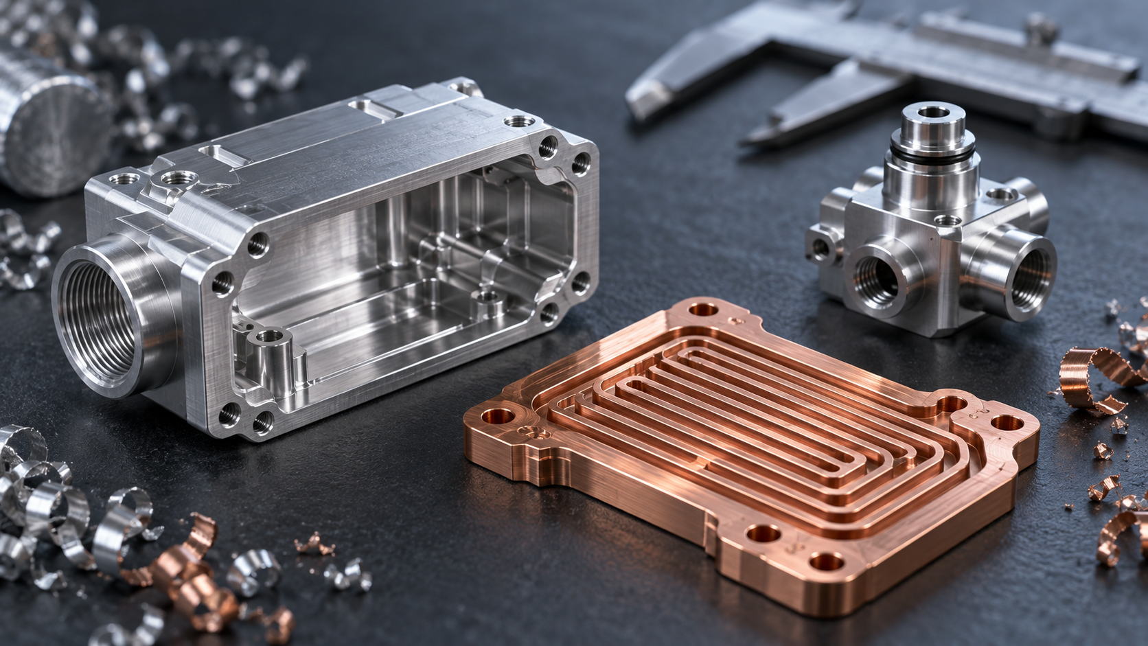
In electronic part machining, what truly keeps CNC machining in the process chain is not the vague claim of "high precision," but the way several types of parts depend on key dimensions. The following breaks them down by part type: for each type, first the key requirements, then how it is usually machined, and finally a typical failure scenario—failure scenarios explain where the problem lies better than parameter tables.
Connectors and fittings: hole positions, threads, coaxiality
For connector housings, terminal blocks, and RF connector sleeves, the key dimensions are concentrated in hole positions and true position, thread profile and blind hole depth, and coaxiality among multiple pin positions. If the hole spacing is slightly off, the pin cannot be pressed into the terminal; if the threaded pilot hole is slightly shallow, the screw cannot be tightened fully and is prone to stripping. Such parts are mostly completed by CNC milling combined with turning, with pin arrays going through drilling and reaming operations and rotational bodies going through turning to ensure coaxiality.
Typical failure: a batch of connectors had hole positions within drawing tolerance, but insertion and removal forces fluctuated greatly during assembly. Investigation showed that the true position datum was chosen as the end face rather than the mounting face; machining was aligned to the end face, and the measured result differed from the assembly datum by one layer. True position itself was not out of tolerance, but once installed it was wrong.
Heat dissipation modules and cooling parts: flatness, roughness, flow channels
For heat dissipation base plates, cold plates, heat pipe press-fit seats, and liquid cooling channel blocks, the key requirements are bonding surface flatness, surface roughness, and flow channel cross-section consistency. If flatness is poor, no amount of interface material can compensate for thermal resistance; if roughness is too high, the actual contact area shrinks and the heat conduction path worsens. Machining is mainly CNC milling; parts with deep flow channels often use a composite of "cast blank + CNC finishing," leaving flow channels to casting and sealing surfaces and mounting surfaces to milling.
Typical failure: a heat dissipation part passed flatness acceptance with a feeler gauge, but when installed on the heat source the temperature rise was high. The reason was that the feeler gauge only measured the edge, while the middle area had a slight depression, and after assembly clamping the middle was the main heat transfer area. The acceptance criteria and the actual bonding area did not match.
Control and valve body types: airtightness, fit clearance, sealing surfaces
For gas path control blocks, micro valve bodies, and sensor housings, the key requirements are airtightness, fit clearance, and sealing surface roughness. Such parts often integrate intersecting channels in a small volume; once the sealing surface has tool marks or burrs, leakage occurs after assembly rather than during machining. Machining mostly uses CNC turn-mill combination, completing multi-directional channels and sealing surfaces in one setup, reducing positional errors caused by repeated alignment.
Typical failure: a valve body passed airtightness testing as an individual piece but micro-leaked after assembly into a component. The reason was that the relative position of the sealing surface and the channel shifted during secondary clamping; it could not be detected on a single piece, and only when the seal ring was pressed off-center on the component was it exposed. For multi-directional channel parts, one setup is used as much as possible precisely for this type of problem.
Operational and structural support parts: strength, dimensional consistency
For panels, brackets, shielding frames, and internal load-bearing parts, the key requirements are strength and dimensional consistency, not single-point high precision. Such parts often use CNC milling combined with sheet metal: the main contour is formed by sheet metal bending, and mounting hole positions and mating surfaces are precision-finished by CNC, balancing cost and consistency. For support parts with large batches and simple shapes, sheet metal itself is the more suitable path.
Typical failure: bracket dimensions as individual pieces were all within the tolerance band, but during batch assembly some interference occurred. The reason was that bending springback fluctuated by batch; a qualified individual piece does not equal batch consistency. When discussing acceptance for such parts, batch consistency is often more worth writing into the requirements than single-piece extreme precision.

Hole positions, threads, flatness, airtightness: how to discuss the key dimensions of electronic part machining
In electronic part machining, what truly causes disputes is often not "whether the precision is sufficient," but how it is dimensioned on the drawing and how it is measured during acceptance. For the four items—hole positions, threads, flatness, and airtightness—each has at least two reasonable ways to write it. If the supplier writes according to A and the customer inspects according to B, the result is that qualified parts are judged unqualified. The following breaks these four items into criteria that can be discussed face to face.
Hole positions: first define the datum, then discuss true position or coordinate tolerance
The most common problem in connector-type electronic part machining is hole positions. When discussing, first confirm three things: what the datum is (the housing's large plane, two locating pin holes, or the end face), whether the dimensioning method is true position or coordinate tolerance, and whether the hole itself has a fit requirement (press-fit pins, locating posts, and screw clearance holes have completely different requirements for hole diameter).
When true position is dimensioned with MMC (maximum material condition), making the hole diameter at the upper limit actually relaxes the position requirement; coordinate tolerance has no such compensation. Mixing the two dimensioning methods on the same drawing scatters the inspection criteria. A common industry practice is to use true position plus a datum system for functional holes, and coordinate tolerance for decorative or wire-passing holes; which one to use should be stated on the drawing and confirmed with the machinist before quotation, along with the inspection method (CMM or dedicated gauge).
Threads: consider pilot hole, thread profile, and blind hole depth together
Threads are rarely the difficulty in electronic part machining, but they are often the point of dispute. For small threads such as M2 and M2.5, pilot hole tolerance and thread profile (metric coarse/fine pitch, whether 6H precision is required) directly affect assembly torque and stripping risk. For blind hole threads, effective thread depth and drill depth must also be clearly stated—marking only "depth 5" is insufficient; tapping to the bottom does not equal effective thread profile reaching the bottom.
For small threads on thin-walled aluminum alloy parts, it is recommended to note on the drawing whether thread inserts (such as wire thread inserts) are allowed, because the life of direct threads in aluminum is limited during repeated disassembly and assembly. This type of structural trade-off falls within the scope of DFM; deciding it before quotation is cheaper than reworking after machining.
Flatness: state clearly whether it is the bonding surface or the entire surface, and how to measure it
Heat dissipation parts, power device bases, and shielding cover bonding surfaces all require flatness, but if "flatness 0.05" does not state whether it is the local bonding area or the entire surface, the result can differ several times over. The smaller the bonding area and the stricter the requirement, the more machining must control clamping stress and cutting heat; otherwise it springs back after the fixture is removed.
The measurement criteria must also be unified: a feeler gauge measures local gap, while a CMM point measurement calculates deviation from a fitted plane; the two are not the same thing. For parts sensitive to interface thermal resistance, the industry often focuses on contact area in the bonding region rather than absolute flatness of the entire surface; the specific allowance should be determined in conjunction with the filling capability of the thermal interface material (thermal pad, thermal grease), rather than copying a number.
Airtightness: test pressure, medium, and leak rate must be written together
Control boxes, valve bodies, and sensor housings in electronic part machining often carry airtightness requirements. Writing only the two words "airtight" makes acceptance impossible; at minimum, state clearly: test medium (compressed air or helium), test pressure (relative pressure or absolute pressure), holding time, and allowable leak rate (or upper limit of pressure drop).
Helium leak testing has high sensitivity but high cost, while the air pressure drop method is cheaper but insensitive to small leaks. Which to choose depends on whether the part's actual working condition is waterproof, dustproof, or refrigerant-proof; it cannot be one-size-fits-all. In addition, state whether sealant is allowed on the sealing surface, because this affects subsequent disassembly and repair. Such criteria are best provided together at the inquiry stage so that the machinist can align in advance on the process (sealing surface roughness, flatness, seal groove dimensions).
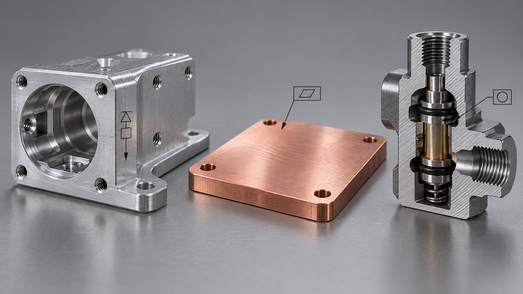
Looking at the four points together, a common thread emerges: most disputes in electronic part machining stem from inconsistency between callouts and acceptance criteria, not from the machine tool being incapable. Locking down these definitions at the drawing stage is far less trouble than arguing about pass/fail after the fact.
How to choose materials: six dimensions from electrical performance and thermal management to machinability
When an electronic part drawing comes in, the material field often reads "AL 6061" or "PEEK," but most people can't explain why. Material selection for electronic part machining isn't about picking the most expensive option—it's about ranking six dimensions by priority and converging them together with the process.
Electrical performance: insulating parts and conductive parts take two different paths
Electronic part machined components that need insulation—such as test fixture bases, high-voltage isolation blocks, and RF support parts—typically use PEEK, PTFE, PPS, or ceramic-filled plastics. They have high volume resistivity, but chip evacuation is poor during cutting and heat builds up easily; PTFE also cold-flows and deforms, so feed rates must be reduced at thin walls.
Conversely, parts that carry current or provide grounding—busbars, shielding covers, contact strips—use copper, copper-nickel, copper-tin, or aluminum. Copper offers excellent electrical and thermal conductivity, at the cost of being gummy to machine and work-hardening quickly, so tooling and cutting fluid must be specially matched.
Thermal management and strength-to-weight: heat-dissipation parts favor aluminum and copper, structural parts depend on load
Thermal modules and cooling parts are judged by thermal conductivity: aluminum is about 150–200 W/(m·K), pure copper about 380–400 W/(m·K). The common industry approach is aluminum for the main body and copper for inserts or heat pipes. Ceramics and specialty plastics withstand higher temperatures but conduct heat poorly, making them suitable only for small heat-flow paths.
Structural support parts are selected by load and vibration environment: stainless steel has good strength but is heavy and difficult to cut; ABS and PC/ABS are light and easy to form, suitable for enclosures and brackets. When lightweight requirements are high, aluminum and engineering plastics are the default starting points. There's no single answer here—it depends on what the part endures within the complete machine.
Corrosion resistance and machinability: two easily underestimated constraints
Outdoor or automotive electronic parts must pass salt spray, damp heat, or chemical cleaning tests. Aluminum requires anodizing or electroless nickel plating, stainless steel should be 304/316, and copper needs anti-oxidation treatment. Once corrosion-resistant material selection determines the surface treatment, the dimension chain and tolerances must change accordingly—this step is best confirmed before the drawing is frozen.
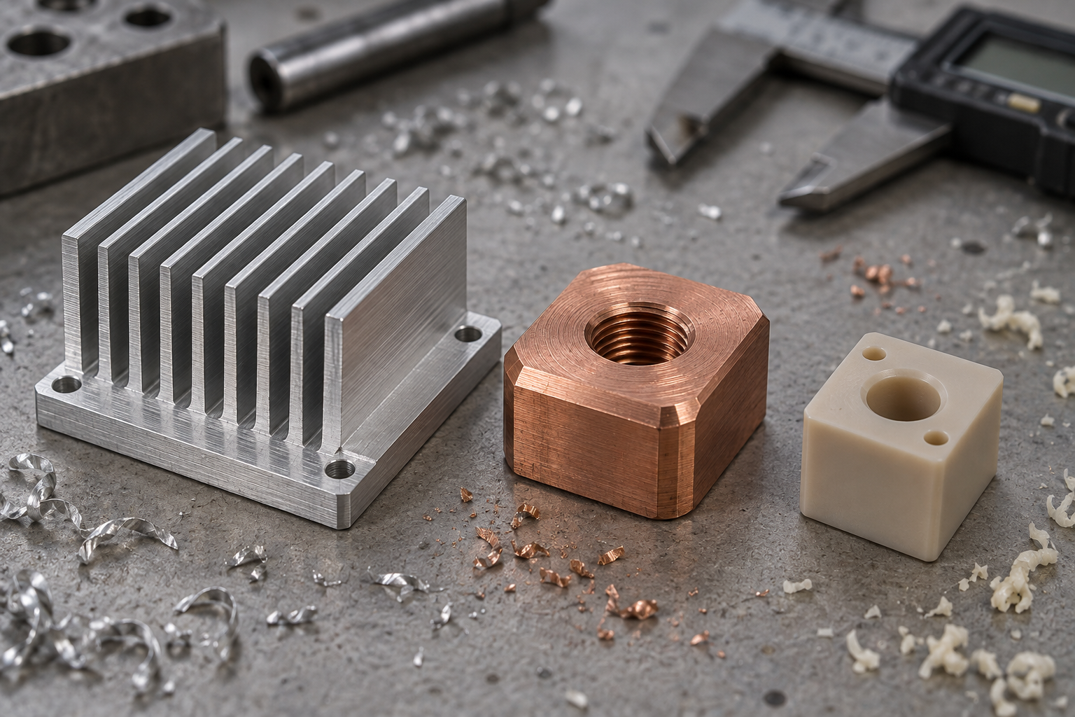
Machinability determines cost and lead time. Copper is gummy and thin walls are prone to chatter; PEEK conducts heat poorly and localized overheating can cause burning; aluminum is the most forgiving, but extremely thin walls will still deform. A common industry rule of thumb: if both copper and aluminum can satisfy the thermal design for the same part, calculate aluminum first—unless the heat flux density truly can't be handled. For specific drawings, it's advisable to confirm tool paths and fixturing methods directly with the machining provider rather than just comparing material unit prices. Heat-dissipation parts favoring aluminum or copper and insulating structural parts favoring PEEK/PTFE are two common pairings, but they are not hard rules.
| Material | Electrical performance | Thermal conductivity W/(m·K) | Strength/weight | Corrosion resistance | Machinability |
|---|---|---|---|---|---|
| Aluminum 6061 | Conductive, can be grounded | ≈150–200 | Medium strength, light | Requires anodizing | Good; extremely thin walls still deform |
| Pure copper/copper alloy | Excellent electrical and thermal conductivity | ≈380–400 | High density, relatively soft | Oxidizes easily, requires treatment | Gummy, work-hardens |
| PEEK | Insulating, chemical-resistant | ≈0.25 | Good strength, light | Excellent | Poor thermal conductivity, prone to overheating |
| PTFE | Insulating, low dielectric | ≈0.25 | Soft, prone to cold flow | Excellent | Difficult to clamp, thin walls prone to deformation |
| 304/316 stainless steel | Conductive, can be grounded | ≈16 | High strength, heavy | Excellent | Difficult to cut, rapid tool wear |
| PC/ABS | Insulating | ≈0.2 | Medium, lightweight | Fair | Injection molding friendly, CNC prone to melted edges |
After ranking all six dimensions, usually only two or three material candidates remain. The next step is not to make the final call, but to hand the candidate materials along with key dimensions to the machining partner for a manufacturability assessment—much of the cost difference in electronics parts machining is actually locked in at the material selection stage. If you need to quickly compare a round of material and process combinations, you can check common grades in the materials library, then cross-reference CNC machining capabilities to confirm whether tolerances and surface requirements match.
DFM: The most easily skipped step in electronics parts machining
Most rework in electronics parts machining does not happen on the machine, but at the moment the drawing is finalized. Wrong hole datum selection, internal fillets smaller than the tool radius, thin-walled parts without stress relief allowance—these problems cost almost nothing to fix with a single annotation change during the quoting stage, but once the blank is cut, changing them means redoing fixtures, reprogramming, and re-inspection. DFM (Design for Manufacturability) is exactly what addresses this stage. Its output is not a polished document, but a series of concrete judgments about "how this callout will be machined and where the cost lies."
Applied to electronics parts machining, the DFM checklist is narrower and harder than general machining: can position tolerances be covered in a single setup, will the tool holder interfere in deep-cavity heat sink shells, what inspection gauge verifies the flatness of valve body sealing surfaces, will thin-walled shielding covers spring back due to residual stress after milling. These are all things that should be clarified before quoting.
What DFM checks in electronics parts machining
- Tolerances and datums: whether position tolerances are called out from assembly datums rather than the modeling origin; whether multiple hole positions can be measured in a single setup using the same datum.
- Tool accessibility: whether deep cavities, narrow slots, and internal right angles exceed the existing tool radius and length-to-diameter ratio range, requiring EDM or structural changes.
- Wall thickness and rigidity: whether thin-walled heat sink shells and slender support posts will deform under clamping and cutting forces, and whether process bosses or split-sequence machining are needed.
- Surfaces and fits: whether the roughness and flatness specifications for sealing surfaces, thermal contact surfaces, and shielding surfaces are clearly stated, and whether feeler gauges or CMM are used.
- Materials and batches: copper sticking to tools, aluminum scratching easily, PEEK absorbing moisture—whether these are matched with the process at the DFM stage.
High-frequency design mistakes: three most commonly overlooked by CAD
The first category is tolerance stacking. Connector hole positions, housing locating posts, and PCB support surfaces each leave a little clearance, and when assembled, interference or contact resistance fluctuations appear. The typical DFM-stage approach is to concentrate critical dimensions onto a single datum and relax the rest, rather than tightening the entire drawing uniformly.
The second category is ignoring tool radius. Internal right angles in cavities and narrow slots at the base of heat sink fins look natural in 3D models, but in milling they require smaller tools and longer overhangs, degrading surface quality and efficiency. The common practice is to add internal fillets or have the process partner specify the minimum machinable radius, then revise the model accordingly.
The third category is stress relief and clamping deformation. Thin-walled electronics enclosures and slender brackets release stress after rough machining, and by finish machining the shape has already changed—dimensions pass but assembly fit fails. DFM will determine in advance whether rough and finish machining should be separated, whether stress relief annealing is needed, and whether aging is required.
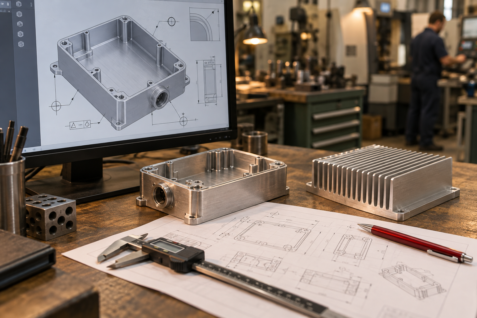
These three categories share one thing in common: they all only surface after machining, but their root causes are all at the drawing stage. Placing DFM review before quoting and before cutting material means changing annotations and models; placing it after first article means changing money and lead times. As for how thorough the review should be—it depends on the part's purpose: ordinary bracket parts need only a rough review, while dimensions that directly determine function, such as valve bodies, thermal contact surfaces, and RF shielding cavities, deserve annotation-by-annotation confirmation. For process capability boundaries, refer to CNC machining capabilities; for material-side choices, see the materials library page.
CNC is only one part of it: how to judge the process combination for electronics parts machining
Equating electronics parts machining with CNC is the most common misjudgment at the inquiry stage. In an electronic assembly, the parts that truly need milling or turning are often functional components like connector seats, valve bodies, and heat sink base plates; enclosures, shielding covers, and brackets are better suited to sheet metal; fixtures, custom air ducts, and rapid validation parts can go through 3D printing first; small-batch enclosures after structural finalization can transition to vacuum casting, then to injection molding for mass production. Each process covers different batch sizes and structural ranges—forcing everything into one process either sends costs out of control or mismatches precision and consistency.
Judging by batch size: CNC prototyping, vacuum casting for small batches, injection molding for mass production
Batch size is the first dividing line. For prototypes and validation parts within a few dozen units, both CNC machining and 3D printing can cover it—the former offers more stable dimensions and surfaces closer to the finished product, the latter offers greater structural freedom with almost no added cost for revisions. Silicone mold duplication (vacuum casting) suits small-batch orders of dozens to hundreds of units that need an appearance and feel close to injection molding; mold cost and lead time are typically lower than injection molding, but per-piece consistency and dimensional precision are generally not as good as CNC. Above several thousand units, injection molding becomes cost-competitive, provided wall thickness, draft angles, and gate locations have been confirmed through DFM at the design stage.
Judging by structure and surface requirements: the boundaries of sheet metal, 3D printing, and CNC
Sheet metal fabrication handles sheet-type parts: enclosures, shielding covers, mounting brackets, heat sink bases. Stamping, bending, and welding can quickly form shapes, but bend springback, post-weld deformation, and hole burrs increase dimensional variation, and the flatness and overlap gaps of shielding covers often need to be confirmed with gauges. 3D printing suits shapes that traditional subtractive methods cannot produce, such as internal flow channels, lattice heat dissipation structures, and custom fixtures, but anisotropy, surface roughness, and long-term dimensional stability need to be evaluated by application. CNC machining suits parts with fit requirements, threads, airtight surfaces, and strict position tolerances, at the cost of setup count and tool interference driving up expenses.
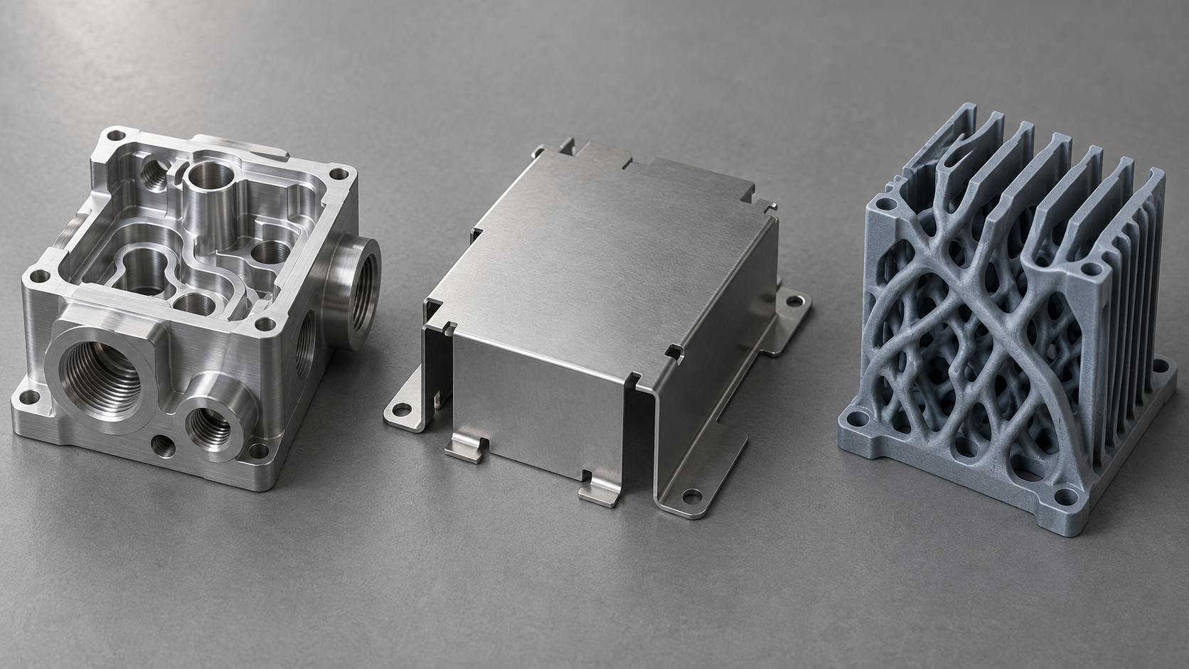
Looking at these processes on a single product line, the usual sequence is: CNC or 3D printing for prototype validation → vacuum casting for small-batch trial production → injection molding for mass production; sheet metal handles enclosures and structural parts, while 3D printing handles fixtures and heat dissipation structures. The core of the judgment is not which process is more advanced, but among the five items of batch size, material, structural complexity, surface requirements, and tolerance specifications, which ones are the true hard constraints.
How to judge whether an electronic parts machining supplier is reliable
First, see whether they actually understood your critical dimensions
Do they proactively raise DFM issues
Inspection criteria and gauges must be clearly stated
How to verify material batch and sample-to-production consistency
Common questions about electronic parts machining
The following questions come from the points most frequently pressed on in electronic parts machining inquiries and prototyping, and the answers are closed out according to the criteria discussed earlier in this article, without making absolute promises.
In electronic parts machining, how should CNC tolerances generally be specified to be reasonable?
First distinguish between "mating dimensions" and "non-mating dimensions." For mating dimensions such as connector hole positions, bearing seats, and sealing surfaces, the common industry practice is to control critical dimensions in the range of ±0.01–0.02 mm; in high-precision scenarios it can reach around ±0.005 mm, but this cannot be promised casually and depends on the material, structural rigidity, and fixturing method. For non-mating outer shapes and clearance positions, ±0.1 mm is usually enough. Marking critical dimensions separately on the drawing and noting the datum is cheaper and easier to inspect than tightening tolerances uniformly across the whole drawing.
For heat dissipation parts, should copper or aluminium be chosen, and how do you weigh it in electronic parts machining?
Look at the thermal conductivity requirement and weight limit. Copper conducts heat better, but its density is about three times that of aluminium, and it is gummy during machining with poor chip evacuation, making thin walls and fine channels harder to control; aluminium is light, easy to machine, and low cost, so most heat dissipation housings and cold plates use aluminium first. If higher thermal conductivity is needed locally, copper inserts or copper-aluminium composite structures can be considered, but the difference in thermal expansion between the two materials and the assembly method must be confirmed in advance. For the final material choice, it is recommended to provide the flatness and surface roughness requirements together to the machining party for evaluation.
How do you prevent deformation of thin-wall electronic enclosures in electronic parts machining?
Thin-wall deformation mainly comes from cutting forces and clamping stress, and it cannot be solved simply by "going slower." Common approaches: multiple light cutting passes, symmetrical material removal, separating roughing and finishing with stress relief arranged in between, and using soft jaws or dedicated fixtures to distribute clamping force. The design side can also cooperate, for example by making the wall thickness within the range where the tool can cut stably, avoiding large thin bottoms, and leaving process bosses on non-appearance surfaces. How thin can be stably achieved specifically needs to be confirmed by trial cutting according to the material and structure by the machining party, and it is not advisable to write extreme values directly on the drawing.
At what stage of electronic parts machining is a DFM report generally done?
It is best done before quoting and before the drawing is frozen. The value of DFM is precisely to pick out tight tolerances, deep cavities, thin walls, sharp internal corners, and locations the tool cannot reach before cutting begins, avoiding the discovery halfway through machining that the design must be changed. Raising it only after the sample is made often means rework and mold modification costs have already been incurred. During inquiry, you can directly ask whether the other party will provide DFM feedback and in what form, which reveals their level of cooperation better than simply comparing unit prices.
For small-batch electronic parts, should CNC or vacuum casting be chosen?
Look at batch size, material, and precision requirements. Within a few dozen pieces, where true material properties or high-precision mating are required, CNC is more reliable; from a few dozen to a few hundred pieces, with a relatively fixed structure, mainly plastic parts, and not extreme precision requirements, vacuum casting (silicone mold duplication) is usually more suitable in terms of cost and lead time. If injection molding mass production will follow, you can first use CNC or casting to validate the structure and assembly, then open the mold. The dimensional consistency and surface results of the two processes differ, so before switching it is recommended to first confirm whether the critical dimensions can be met.
Key takeaways
- The key dimensions in electronic part machining are concentrated in four categories: hole positions, threads, flatness, and airtightness, which respectively correspond to assembly contact, fastening, heat dissipation bonding, and media sealing.
- The reason CNC machining fits the electronics industry is small complex parts, broad material compatibility, and good batch consistency; micron-level tolerances are common in the industry, but each feature must be confirmed item by item.
- Material selection should be ranked by six dimensions: electrical performance, thermal management, strength, weight, corrosion resistance, and machinability. The priority is determined by part function; there is no universal optimal solution.
- DFM review should be moved forward to the drawing stage, focusing on deep cavities, thin walls, sharp internal corners, and tolerance stacking, which are high-frequency sources of rework and cost overruns.