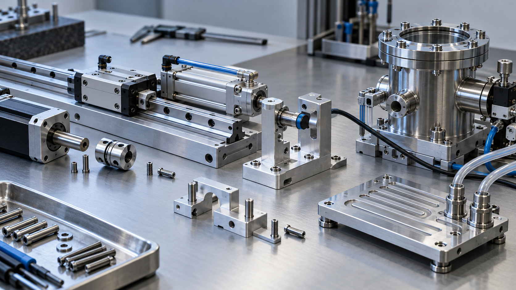
What Are Equipment Parts? Distinguishing Parts, Components, and Assemblies
When equipment stops, the problem may not be with the entire machine. It could be an offset installation datum on a guide rail, a seal that is incompatible with the medium, or a mismatched interface on a sensor or valve. Understanding equipment parts requires more than listing them by appearance or material; it is also essential to consider the task each part performs within the equipment's functional chain.
In an engineering context, a "part" usually refers to a single component that cannot, or should not, be further disassembled, such as a locating pin, shaft, flange, or support plate. A "component" is an assembly of multiple parts that can independently perform a specific action or function, such as a linear motion component consisting of a guide rail, slider, and mounting plate, or an actuating component consisting of a cylinder, fittings, and mounting base. "Parts and components" is a broader collective term that may refer either to an individual part or to a component with assembly relationships. These distinctions are basic engineering terminology; the naming conventions used in a specific company's BOM and drawings may differ.
It is also necessary to distinguish hierarchical concepts from manufacturing methods. Castings, forgings, machined parts, and sheet metal parts describe forming or processing routes, not a different component hierarchy. The same equipment base may first be cast to create a blank and then CNC-machined to form datum surfaces and mounting holes; a support assembly may also include machined plates, fasteners, and standard structural profiles. Classification should therefore return to equipment function: does the item handle motion, positioning, inspection, fluid control, or load-bearing and support? Only then can the requirements for interfaces, tolerances, materials, environment, and inspection be determined.
What Equipment Parts Are There? Six Categories Classified by Equipment Function
- Motion and transmission: Linear guide rails, ball screws, couplings, and timing pulleys handle linear movement, rotary transmission, or speed conversion, respectively. Guide rails and ball screws must be evaluated together with the load, travel, stiffness, installation datums, and lubrication conditions rather than by nominal dimensions alone.
- Positioning and clamping: Locating pins, locating blocks, toggle clamps, and custom fixtures are used to repeatedly establish positions, restrict workpiece movement, or maintain an assembly orientation. The key considerations are the positioning datums, force direction, loading and unloading space, and whether the clamping force will deform thin-walled parts.
- Inspection and control: Photoelectric, proximity, pressure, and temperature sensors provide the control system with feedback on position, presence, or process parameters. Detection distance, installation space, signal interface, response conditions, and the operating environment collectively determine suitability.
- Pneumatic, hydraulic, and vacuum: Cylinders provide linear actuation, solenoid valves switch the medium, and vacuum valves and seals maintain evacuation, isolation, or suction functions. The medium, pressure, temperature, leakage requirements, and maintenance method must be checked together.
- Conveyance and support: Conveyor rollers, casters, aluminum-profile supports, and mounting plates address material transfer, equipment load-bearing, and module mounting. Supports are evaluated for stiffness, connection method, and available space; conveying components must also account for load, friction, cycle time, and cleaning requirements.
- Temperature and Piping: Heaters, cooling plates, pipe fittings, and flow-channel components are used for heating, heat dissipation, and media conveyance. In addition to temperature stability, it is necessary to confirm whether the flow channels, sealing grooves, wall thickness, interface orientation, and subsequent cleaning are feasible.
Common Equipment Parts in Automation Equipment: Linear Guides, Couplings, Sensors, and Cylinders
Automation equipment parts cannot be replaced based solely on appearance or specifications. First determine what action the equipment must perform, then verify the load, datum, mounting interfaces, operating environment, and maintenance space. Linear guides provide stable motion, couplings transmit torque, sensors confirm position or status, and cylinders perform linear pushing and pulling; interface mismatches may appear as motion sticking, vibration, false detection, or incomplete movement, respectively.
- Linear Guides: Load-Bearing and Guidance. Key points to verify include load direction, rigidity, motion accuracy, parallelism between the guides, mounting datums, and lubrication conditions. If the mounting surfaces are not coplanar, the carriage may experience abnormal resistance. At the drawing stage, the datum surfaces and mounting hole positions should be clearly specified rather than merely indicating the guide model.
- Couplings: Connecting the Motor to the Actuator. Shaft diameter, keyway or clamping interface, concentricity, permissible misalignment, and transmitted torque collectively determine suitability. Although couplings can compensate for some assembly errors, they cannot replace shaft-line alignment. When the compensation capacity is insufficient, motor vibration and bearing loads will increase.
- Sensors: Detecting Position, Distance, or Status. Confirm the sensing distance, target material, installation space, signal interface, response requirements, and environmental conditions such as oil mist, dust, or coolant. Sensors with the same housing dimensions may have different output methods and detection conditions, so they cannot be selected solely based on the mounting thread.
- Cylinders: Performing Pushing, Pulling, Clamping, or Positioning Actions. Stroke, thrust, mounting method, speed adjustment, cushioning structure, and operating medium must all match the mechanism. A cylinder having sufficient stroke does not necessarily mean that the action will be reliable. If the load is eccentric, guidance is insufficient, or maintenance space is too limited, the piston rod may still wear or stick.
Therefore, equipment part selection should connect “action—interface—consequences of loss of control” during inspection: for linear guides, examine the motion datum; for couplings, examine the shaft-line relationship; for sensors, examine the detection conditions; and for cylinders, examine the load and mounting. During purchasing or outsourcing, in addition to the model and quantity, provide the mounting hole positions, mating dimensions, load direction, stroke, signal or pneumatic interfaces, and the space required for disassembly and lubrication.
Why Precision Equipment Parts Are Difficult to Machine: Vacuum Chambers, Cooling Plates, and Showerheads
Equipment parts used in specialized equipment such as semiconductor manufacturing systems commonly feature high variety, low volume, special dimensions, and combined requirements for vacuum performance, cleanliness, corrosion resistance, and thermal stability. The challenge is not merely to machine the 3D model, but to ensure that the material, structure, datums, sealing, and inspection methods all work together.
Vacuum Chambers: Sealing Surfaces, Leakage, and Machining Deformation
A vacuum chamber must first ensure the relative positions of the flanges, sealing grooves, and connection holes. Tool marks, localized deformation, or burrs on the sealing surfaces may affect sealing. Uneven chamber wall thickness, deep-cavity cutting, and multiple setups may cause deformation after residual stresses are released. Drawings should clearly specify critical datums, surface requirements for sealing areas, cleaning or oil-free requirements, and how leakage, dimensions, and appearance are to be inspected, rather than simply stating “high precision.”
Cooling Plates and Showerheads: Bottlenecks Caused by Internal Structures and Microholes
The core constraints of cooling plates are typically flow-channel layout, enclosed structures, wall thickness, and temperature uniformity. During machining, attention must be paid to deep holes, thin walls, and flatness after the cover plate is sealed. Inspection must not be limited to external dimensions; it must also confirm that the flow channels are open throughout and that the interfaces match.
Showerheads may use brittle materials and contain hundreds or thousands of microholes. Hole diameter, positional error, and defects at the hole openings affect gas distribution and increase the difficulty of controlling fracture, edge chipping, and cleanliness. An industry article may have presented microhole and micrometer-level machining data for a specific equipment solution, but these are examples from a single solution and cannot be treated as universal specifications for all equipment parts. Actual manufacturing should develop process and inspection plans based on the material, hole diameter, aspect ratio, and functional distribution.
For this type of equipment part, the key controls are to unify machining datums, minimize unnecessary setup changes, and reserve measurement surfaces, locating holes, or interfaces for dedicated gauges at the drawing stage. Separate process inspection, final inspection, and cleaning requirements should be defined for sealing surfaces, flow channels, microholes, and clean areas.
DFM Inspection for CNC-Machined Equipment Parts: From CAD Geometry to Manufacturability and Inspectability
The fact that an equipment part can be modeled in CAD does not mean that the tools, fixtures, and measuring instruments can produce it consistently. Before CNC machining, convert the drawing item by item into three questions: Can the tool reach the feature? Can the workpiece be securely fixtured? Can the critical features be measured?
Tool Accessibility for Equipment Parts: Check Deep Cavities, Internal Corners, and Tool-Retract Space First
Deep cavities, small openings, and excessively deep internal corners limit tool diameter and tool extension length, while sharp corners are also typically affected by the actual tool nose radius. During drawing review, confirm that the tool can enter from a reasonable direction, and reserve space for tool retraction, chip evacuation, and measurement. Non-functional sharp corners can be changed to clearly defined radii, while deep cavities can be provided with clearance or their parting structure can be adjusted.
Fixturing and Datums for Equipment Parts: Reduce Errors Caused by Repeated Positioning
If a component of the same equipment requires multiple setups, re-establishing alignment each time increases the risk of datum transfer. During design, priority should be given to using unified machining datums, arranging function surfaces for continuous machining, and checking whether the fixture provides sufficient support and clamping positions. For thin-walled parts, deformation caused by cutting forces and heat must also be considered. Where necessary, add machining allowance, support areas, or staged material removal.
Tolerances and inspection of equipment components: apply tight accuracy requirements only to functional surfaces
Setting tight tolerances for every dimension often increases machining and inspection difficulty without necessarily improving equipment performance. Priority should be given to controlling features that affect fit, sealing, alignment, and motion, while other dimensions should use tolerance zones that adequately support their functions. For critical hole locations, flatness, coaxiality, or position, specify measurement methods such as coordinate measuring machines, gauges, depth measuring instruments, or dedicated inspection fixtures at the drawing stage, and provide inspection surfaces. When material strength or hardness is relatively high, tool wear, heat generation, and deformation risks should also be reviewed rather than considering only the nominal material strength.
How to determine technical requirements for equipment components: align function, tolerances, materials, and environment
The technical requirements for equipment components should not begin with the assumption that “higher accuracy is always better”; they should instead be derived from the consequences of failure. Tolerances should be allocated first to functional surfaces that affect fit, sealing, alignment, and motion; external dimensions unrelated to function should not all be assigned tight tolerances. Materials, surface treatments, and inspection methods must also match the operating environment and maintenance practices.
The constraints for guide rails, sealing grooves, and vacuum chambers are different
| Equipment components | Technical requirements to prioritize | Key points for drawing and manufacturing inspection |
|---|---|---|
| Linear guide rails and mounting surfaces | Load, stiffness, motion accuracy, parallelism, lubrication | Unify the mounting datums; verify the flatness and relative positions of the mounting surfaces; and provide maintenance space |
| O-rings and sealing grooves | Medium, temperature, compression, groove dimensions, surface condition | Confirm that the sealing material is compatible with the medium; inspect the groove width, groove depth, chamfers, and sealing-surface roughness |
| Vacuum chambers | Corrosion resistance, sealing surfaces, leakage, cleanliness, surface roughness | Evaluate wall thickness and machining deformation; define cleaning, leak testing, and acceptance methods after welding or machining |
The key issue for guide rails is whether the motion pair can maintain its relative position under load; for O-rings, it is whether compression and the medium environment can form a stable seal; vacuum chambers must also address internal-wall cleanliness, minor leakage, and deformation caused by machining multiple faces. All three are equipment components, but they cannot be subject to the same tolerances, materials, or surface requirements.
Material selection for equipment components must be evaluated together with the process and environment
Material strength, hardness, corrosion resistance, and thermal stability directly affect tool wear, heat generation, deformation, and subsequent surface treatment. When selecting materials, also confirm the working medium, temperature, load, cleanliness requirements, and maintenance method before determining whether CNC machining, sheet metal fabrication, or another manufacturing route is suitable. The final technical requirements should clearly specify functional datums, critical tolerances, material condition, surface treatment, cleanliness requirements, and inspection items, rather than simply stating “high precision” or “high strength.”
What information should be prepared before outsourcing equipment parts: from drawings to the inspection checklist
Before outsourcing equipment parts, clearly define “what needs to be made, the environment in which it will operate, and how it will be accepted.” Basic information includes 2D drawings, 3D models, material grade and condition, quantity, as well as critical datums, threads, fits, and assembly interfaces.
- Functional requirements: Identify features that affect motion, positioning, sealing, load-bearing, or alignment, and avoid assigning tight tolerances to every dimension.
- Manufacturing requirements: Specify surface treatment, roughness, chamfers, deburring, cleaning, or oil-free requirements, and state the operating medium and temperature.
- Inspection requirements: List the dimensions, geometric tolerances, threads, sealing surfaces, and appearance items that must be measured; where necessary, specify inspection records or dedicated gauges.
- Assembly information: Provide interfaces with adjacent parts, installation orientation, maintenance clearance, and interchangeability requirements to reduce the risk of suppliers having to infer the function from a single part.
For standard components, focus on verifying specifications, loads, interfaces, and interchangeability. For custom equipment parts, also confirm the machining route, fixturing plan, datum transfer, and measurement method. When comparing manufacturing options, do not look only at nominal accuracy. Confirm that critical functional surfaces can be machined consistently and that measurement results corresponding to the drawing requirements can be provided.
FAQ: Common Questions About Equipment Parts
Equipment parts should not be evaluated solely by their appearance or nominal accuracy. The assessment must also consider equipment function, installation interfaces, operating environment, and inspection methods. The questions below address several key distinctions involving classification, accuracy, CNC manufacturability, and inspection of vacuum parts.
How should equipment parts be classified?
Prioritize classification by equipment function, such as motion and transmission, positioning and clamping, detection and control, pneumatic/hydraulic/vacuum systems, conveying and support, and temperature control and piping. This connects parts with their load, travel, sealing, detection, or load-bearing tasks, rather than cataloging them only by material or appearance.
Do all equipment parts require high precision?
No. Tolerances should primarily be assigned to functional surfaces that affect fit, sealing, alignment, and motion. Support components may place greater emphasis on stiffness, interfaces, and assembly datums; guide rails on parallelism and motion accuracy; and sealing grooves should be evaluated in conjunction with the medium, temperature, and compression amount.
Why should deep cavities, thin walls, and fixturing be checked before CNC machining equipment parts?
These features directly affect tool accessibility, cutting stiffness, deformation control, and the repeatability of datum establishment. During drawing review, confirm that the tool can reach the deep cavity, that thin walls have adequate support, that sharp corners are compatible with actual tool geometry, and that the fixturing and measurement plans are determined in advance.
How do the inspection requirements for vacuum chambers differ from those for ordinary support components?
Ordinary support components are typically inspected mainly for overall shape, hole locations, installation interfaces, and load-bearing-related dimensions. Vacuum chambers also require attention to sealing surfaces, leak control, surface condition, cleanliness requirements, material corrosion resistance, and machining or welding deformation. The specific inspection items should be determined by the operating environment and acceptance requirements; the same dimensional checklist cannot be applied universally.
Key takeaways
- Equipment parts should be classified according to the equipment's functional chain rather than simply listed by material or appearance.
- General-purpose parts emphasize specifications, load, interfaces, and interchangeability, while special precision parts must also control sealing, cleanliness, deformation, and environmental compatibility.
- CAD can represent geometry, but that does not mean tools, fixtures, and measuring instruments can reliably produce or verify it; deep cavities, thin walls, sharp corners, and unnecessarily tight tolerances should all be reviewed at the drawing stage.
- Tolerances should be allocated first to functional features that affect fit, sealing, positioning, and motion, while datums and inspection methods should be defined at the same time.
- Before outsourcing, prepare complete drawings, 3D models, material conditions, critical datums, surface treatments, cleaning requirements, and inspection items.



