Metal Semi-Solid Forming vs. Liquid Die Casting: Why Thin-Walled Aluminum Alloy Parts May Benefit
For precision thin-walled aluminum alloy parts, the value of metal semi-solid forming is not simply that it “flows more easily.” Semi-solid slurry contains a certain volume fraction of spherical primary solid particles, and its flow behavior differs from that of fully liquid metal: filling is generally smoother, and the tendency for splashing and air entrapment may be reduced; the lower filling temperature may also lessen thermal shock to the mold. During solidification, reduced liquid-phase shrinkage, together with a finer and more uniform microstructure, may also improve dimensional stability and near-net-shape forming potential.
However, this is not a defect-free process. The temperature, solid-phase morphology, holding conditions, and transfer method after slurry preparation directly affect metered pouring and filling at the ends of thin walls; inadequate mold venting can still cause gas porosity or incomplete filling; cold shuts may occur at flow convergence locations, while abrupt thickness changes and localized hot spots may still lead to shrinkage porosity and shrinkage cavities. Therefore, the advantages of semi-solid forming must be evaluated together with slurry preparation, transport, venting, injection, and solidification control, rather than based solely on whether the part is “thin.”
Existing research supports the engineering potential of semi-solid slurry in terms of flow stability, certain air-entrapment risks, feeding behavior, and mold thermal load, but it is insufficient to establish universal minimum wall thicknesses, dimensional tolerances, porosity limits, or mass-production yields for all precision thin-walled parts. Project decisions should return to the part structure, internal quality requirements, subsequent machining or heat treatment, production volume, and whether the slurry can be prepared and transferred consistently. Subsequent filling and solidification simulations and mold trials should focus on the ends of thin walls, flow convergence areas, and localized thick sections.
How to Choose Between Rheocasting and Thixoforming: Slurry Preparation, Holding, and Transport
Process selection for metal semi-solid forming should not be based solely on whether the part has thin walls; it should also consider whether the slurry can remain stable from preparation through mold filling. Rheocasting generally transfers and forms the metal slurry directly after preparation. The process flow is relatively short, but it places high demands on slurry holding, transport distance, temperature uniformity, and metered pouring. If the slurry undergoes a temperature drop, solid-phase segregation, or a change in flow behavior during transfer, incomplete filling may occur at the ends of thin walls.
Thixoforming, by contrast, focuses more on reheating and forming a preform or semi-solid billet. It reduces reliance on transporting high-temperature slurry over long distances, but the microstructure, solid-phase distribution, flow behavior, and batch-to-batch consistency after reheating must be confirmed. For aluminum alloy parts with long thin walls, multiple branches, or critical sealing surfaces, engineering reviews should compare the loading, heating, transfer, and filling windows of the two routes separately, rather than directly equating “thin walls” with semi-solid forming.
TBR and FCR Slurry-Preparation Equipment: How Literature Examples Affect Engineering Decisions
The TBR conical-barrel equipment described in the literature uses continuous cooling and mechanical shearing to progressively break up primary dendrites and promote a rounder, finer morphology. FCR forced-convection equipment uses helical stirring to create circulating flow and adjusts the shear conditions through blade geometry, rotational speed, and stirring time. A sealed environment and protective atmosphere help reduce gas absorption and oxidation. The key is not the equipment name itself, but how cooling, shearing, and atmosphere work together to affect slurry viscosity and transport stability.
Data such as a TBR slurry-preparation time of less than 8 seconds are specific examples from particular literature equipment and cannot be treated as universal specifications for all semi-solid equipment. Actual selection should also verify slurry holding time, transfer path, metering error, mold-entry temperature, and batch variation during continuous production. If these conditions cannot be controlled consistently, a thixoforming route or another forming process may make it easier to establish a repeatable manufacturing window.
How Semi-Solid Slurry Affects Thin-Wall Filling, Air Entrapment, and Solidification Feeding
The key to semi-solid metal forming is not simply making aluminum alloy “flow more easily,” but changing the metal’s rheological behavior during filling and solidification. The slurry contains a certain proportion of rounded primary solid particles, and its apparent viscosity is usually higher than that of liquid metal. Flow is therefore more stable, while severe splashing and surface rolling may be reduced. As a result, the risks of air entrapment and oxide-film entrainment in thin-wall, long-flow-path sections, corners, and flow-convergence areas may be controlled. However, this does not mean that porosity or incomplete filling will not occur.
Thin-Wall Ends and Flow-Convergence Areas Remain Risk Points in Semi-Solid Filling
The ends of thin walls are particularly susceptible to temperature drop and premature solidification. If the slurry temperature, solid-phase morphology, or injection conditions are mismatched, misruns, cold shuts, or poor bonding may still occur. When multiple metal streams converge near holes, ribs, or enclosed cavities, insufficient gas-venting paths may also result in internal porosity. The higher viscosity of semi-solid slurry helps stabilize flow, but it also increases the requirements for runner cross-sections, venting channels, and pouring continuity.
During solidification, semi-solid metal undergoes relatively less liquid-phase shrinkage. Its fine and relatively uniform microstructure may improve feeding conditions and reduce the tendency toward localized shrinkage cavities and shrinkage porosity. However, locally thick sections, isolated bosses, and abrupt thickness transitions may still become late-solidifying hot spots. If the feeding path is closed prematurely, defects will remain. The final result depends on the solid fraction, slurry temperature, pouring method, mold venting, filling speed, and solidification sequence; it cannot be judged solely from the process name “semi-solid.”
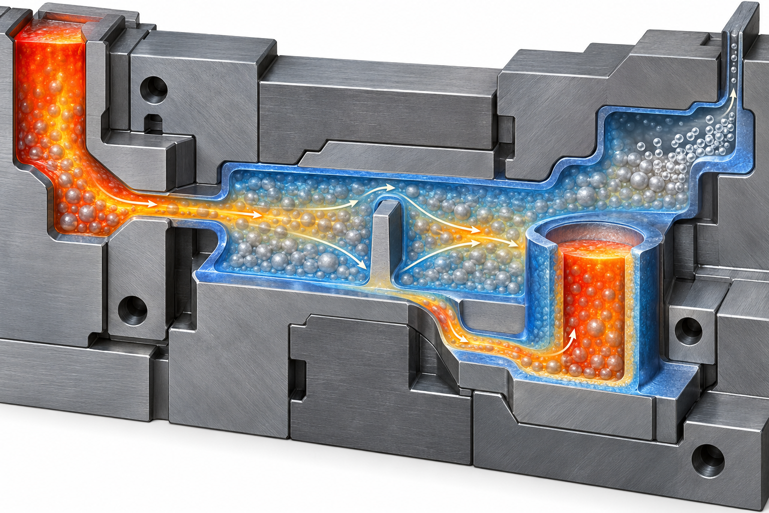
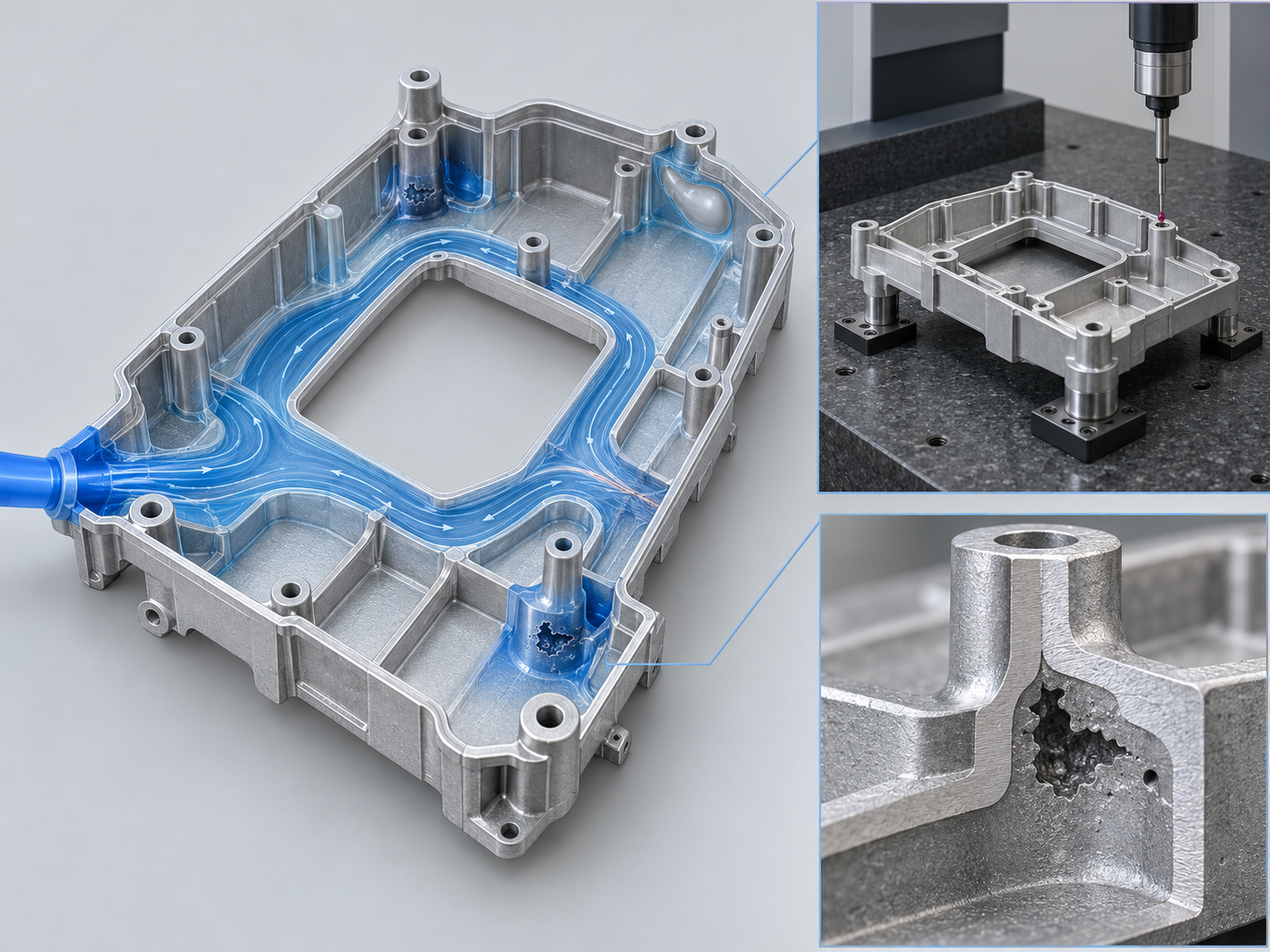
Accordingly, validation should assess the filling time at the thin-wall end, bonding risk at flow-convergence locations, gas accumulation in enclosed cavities, the solidification sequence of thick sections, and the feeding path. Filling and solidification simulation can provide only a risk assessment; confirmation still requires dimensional inspection after mold trials, together with appropriate internal-defect inspection. Comparing only nominal processes or adjusting just one injection parameter is generally insufficient to explain the final quality.
Common Defects in Semi-Solid Aluminum Alloy Forming: The Control Chain from Slurry Preparation to Solidification
Defect control in semi-solid forming cannot focus only on the injection stage. Cooling, shearing, and the protective atmosphere during slurry preparation alter the morphology of the primary solid phase and also affect oxide-film formation and gas absorption risks. Fine, rounded, and stably distributed solid particles facilitate smooth slurry transfer. If the temperature, shearing, or holding conditions fluctuate, slurry viscosity and flow continuity may change, narrowing the subsequent thin-wall filling window.
During holding and transfer, time, temperature, and solid-phase distribution must be controlled to avoid localized premature solidification or unstable metered pouring. Insufficient runner continuity, poorly positioned overflows, and inadequate venting channels may cause incomplete filling, porosity, or poor bonding at flow-convergence locations. Enclosed cavities and thin-wall ends require particular attention to gas accumulation and end-of-fill misruns. During solidification, thick sections, isolated hot spots, and feeding distances should be monitored. Reduced liquid-phase shrinkage does not mean that shrinkage porosity or shrinkage cavities cannot occur; internal defects may still form when the local solidification sequence is unfavorable.
Therefore, simply increasing injection speed or changing a single temperature parameter generally cannot resolve problems spanning multiple stages. Engineering validation should correlate slurry-preparation records, transfer conditions, filling simulation, and mold-trial results, with particular attention to thin-wall ends, flow-convergence areas, and thick sections. During acceptance, do not inspect appearance alone. Combine it with critical dimensional measurements and select sectioning, CT, or other applicable internal-quality inspection methods according to the part requirements. Specific defect grades and acceptance criteria must be confirmed in the drawings and quality agreement.
DFM Design for Thin-Wall Aluminum Alloy Parts: Wall-Thickness Transitions, Radii, and Venting Space
DFM review for semi-solid metal forming should not focus only on whether a part can be made “thin.” It must also determine whether the slurry can fill continuously, whether gas can escape, and whether local heat can be released effectively. The initial design review should first examine wall-thickness distribution and minimize sudden thinning, sudden thickening, and isolated thick sections. If a thin wall connects directly to a boss, rib, or mounting seat, a gradual transition should be used, with radii to reduce stress concentration and localized stagnant flow. The specific minimum wall thickness cannot be applied independently of the alloy, part size, mold structure, and forming parameters; it must be confirmed through simulation and mold trials.
Wall Thickness and Reinforcing Structures in Semi-Solid Metal Forming
Ribs should not simply be stacked onto thin-wall surfaces. Overly thick rib roots, enclosed bosses, and deep cavities can easily form localized hot spots, increasing the risks of shrinkage porosity, shrinkage cavities, or discontinuous filling. Ribs should be arranged in accordance with load directions, while space should be preserved for demolding, venting, and subsequent machining. Hole locations, sealing surfaces, and datum surfaces should also be identified in advance to prevent weld lines or internal defects from ultimately occurring in functional areas.
Allow Space for Runners, Overflows, Vents, and Demolding
When pursuing thin external walls, do not reduce the space available for runners, overflow grooves, and venting channels. Thin-wall ends, flow-convergence areas, and enclosed cavities should be treated as priority venting regions, and filling simulation should be used to check gas accumulation and premature-solidification locations. The demolding direction, parting line, and ejector positions also affect holes, ribs, and cosmetic surfaces. If subsequent CNC machining is required, machining datums and allowances should be defined simultaneously to prevent shrinkage porosity, gas pores, or dimensional instability from being exposed after machining. Wall thickness, tolerances, and machining allowances should ultimately be confirmed through drawing review, mold-trial data, and dimensional and internal-quality inspection results.
Filling and Solidification Simulation and Mold-Trial Validation: How to Confirm Semi-Solid Forming Feasibility
Whether semi-solid forming is suitable for a particular thin-wall aluminum alloy part cannot be determined solely from the slurry designation or the part’s appearance. The 3D model, gating system, and mold-venting plan should first be incorporated into filling and solidification simulation. Particular attention should be paid to whether insufficient filling occurs at thin-wall ends, whether unfavorable weld lines form where multiple flow streams converge, and whether local thick sections solidify late without effective feeding. Enclosed cavities, deep rib roots, and isolated bosses should also generally be classified as high-risk areas.
Which process variables should be validated in semi-solid forming simulations?
Simulation should not only compare whether the cavity is ultimately filled; it should also compare how changes in slurry preparation, holding, and transfer conditions affect continuity. Slurry temperature, solid-phase distribution, pouring position, runner cross-section, and overflow and vent locations all alter the filling sequence and the locations where gas accumulates. Simulation results should be assessed in conjunction with the actual die structure; software predictions must not be treated directly as commitments regarding dimensions, tolerances, or porosity grades.
A semi-solid forming die trial should not focus only on appearance
During the die-trial stage, the inspection sequence should be established according to the drawing: first confirm datum relationships, critical hole locations, flatness, sealing surfaces, and machining allowances, then inspect the internal quality of thin-wall regions and flow-convergence areas. Defects such as gas pores and shrinkage porosity must be assessed using appropriate section inspection, CT, or other internal inspection methods; acceptance levels should be determined by the part’s function and project requirements. If the part will also undergo heat treatment, welding, or CNC finishing, validation samples should be evaluated in their final condition.
In A356 research cases, parts weighing approximately 285 g and 325 g were reported, along with a slurry supply of approximately 2 kg and a forming cycle of less than one minute. However, these data applied to specific experimental conditions and cannot serve as general production-capacity or project-takt-time commitments. Ultimately, based on simulation, die-trial dimensions, internal defects, and functional results, the project should be classified as ready for introduction, requiring optimization, or better suited to another forming route.
Engineering evaluation checklist before introducing a metal semi-solid forming project
Metal semi-solid forming should not be selected solely because a part is thin. At project initiation, first determine whether the part truly requires near-net forming and whether liquid die casting, CNC machining, or another aluminum alloy forming route can meet the requirements with a simpler process. The value of the semi-solid route is generally related to internal porosity, dimensional stability, subsequent machining volume, and structural complexity.
- [object Object]
- [object Object]
- [object Object]
- [object Object]
The final decision should be based on simulation, die-trial, and inspection data: focus on whether the ends of thin walls are insufficiently filled, whether unfavorable welds form at flow-convergence areas, and whether thick sections present a risk of shrinkage porosity or shrinkage cavities. These findings should be confirmed through dimensional inspection and appropriate internal quality inspection. If slurry preparation, transfer, or venting conditions cannot be maintained consistently, switching to liquid die casting, CNC machining, or another route may be more reliable. Specific wall thicknesses, tolerances, porosity grades, and production-volume limits must be confirmed based on the part and equipment conditions; generic thresholds must not be applied indiscriminately.
Frequently asked questions about metal semi-solid forming and thin-wall aluminum alloy parts
Whether metal semi-solid forming is suitable for a particular thin-wall aluminum alloy part cannot be determined by wall thickness alone. Slurry preparation and transfer conditions, die venting, internal quality requirements, subsequent machining or heat treatment, production volume, and the inspection plan must also be considered together. The following questions can serve as a quick review checklist during project evaluation.
Is semi-solid forming suitable for all thin-wall aluminum alloy parts?
It is not suitable to make a blanket determination. Parts with long thin-wall flow paths, complex flow convergence, enclosed cavities, or stringent internal porosity requirements may benefit from more stable filling and lower liquid-phase shrinkage, but this must still be confirmed through filling and solidification simulation, die trials, and internal quality inspection.
What are the main differences between rheocasting and thixoforming?
Rheocasting typically involves holding, transferring, and metered pouring immediately after slurry preparation. The process is relatively short, but it imposes stricter requirements on slurry temperature, solid-phase distribution, and transfer stability. Thixoforming typically involves a preformed billet or reheating of the slurry, and its process organization is different. The flow behavior after reheating and batch-to-batch consistency must be validated separately.
Can semi-solid forming completely eliminate porosity and shrinkage cavities?
No. Semi-solid slurry is expected to reduce the risk of some entrapped-air, oxidation, and shrinkage defects. However, porosity, incomplete filling, cold shuts, shrinkage porosity, or shrinkage cavities may still occur if slurry preparation and protection, air entrapment during transfer, mold venting, localized thick sections, and solidification feeding are not properly controlled.
What information should be provided first during the DFM stage?
It is recommended to first provide the 3D model, material grade, critical wall thicknesses and tolerances, sealing-surface and hole-location requirements, internal quality grade, annual demand, subsequent CNC machining or heat-treatment requirements, and acceptable inspection methods. This information helps compare semi-solid forming with other aluminum-alloy manufacturing routes.
Key takeaways
- Semi-solid slurry contains spherical or near-spherical primary solid particles. Filling is generally smoother and liquid-phase shrinkage is relatively reduced, but slurry preparation, transfer, and metered pouring require tighter control.
- Rheocasting has a relatively short process flow, but relies more heavily on holding, transporting, and rapidly metering the slurry after preparation. Thixoforming, by contrast, requires careful evaluation of the microstructure and temperature uniformity of the preform or reheated material.
- Gas porosity, incomplete filling, cold shuts, shrinkage porosity, and shrinkage cavities may still occur. Defect control must cover slurry preparation and protection, mold venting, filling paths, feeding during solidification, and localized hot spots.
- Thin walls, abrupt thickness changes, isolated bosses, and unreasonable flow convergence can amplify process risks. During the DFM stage, wall-thickness transitions, fillets, runners, overflows, vents, draft, and machining datums should be reviewed together.
- Available data are insufficient to support universal thresholds for minimum wall thickness, tolerances, solid fraction, or porosity. Final decisions should rely on filling and solidification simulation, mold trials, dimensional inspection, and internal quality validation.