Define these three things first: the batch boundaries of precision connector injection molding
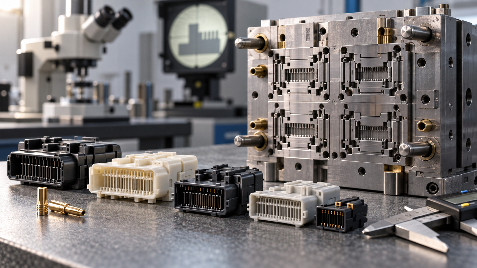
This memo is written for the person placing the order. Mass production of precision connector injection molding is not something you can complete by cutting a set of sample molds and quoting a unit price from the drawing. What really determines whether the project goes smoothly are three boundaries:
- Terminal pitch and wall thickness. For fine-pitch connectors below 0.5 mm pitch, the plastic walls between terminals often fall in the 0.15–0.25 mm range. Thin plastic and long flow paths affect both filling and weld line strength. The smaller the pitch, the narrower the margin for error in both mold and injection molding.
- Annual volume and batch rhythm. Annual volumes of tens of thousands versus millions of parts require two completely different approaches to mold cavitation, runner balance, whether to use hot runners, and whether to automate insert placement. Procurement needs a clear annual volume and monthly fluctuation range before discussing molds.
- The combination of material and tolerance. High-temperature engineering plastics such as LCP, PA9T, PA46, and PBT differ considerably in shrinkage, anisotropy, and moisture absorption; changing materials on the same drawing requires recalculating mold compensation values for key dimensions. Tolerances are not set independently — they are set together with material, gate location, and mold temperature.
Before placing an order, ask yourself three questions: What is the minimum plastic wall at the terminals? What is the annual volume and peak monthly volume? Among the key dimension tolerances, which ones are truly function-related? If you cannot answer these three clearly, the mold plan and quotation that follow are built on sand.
This memo follows the order of follow-up work: first the trade-off sequence between material and tolerance, then what the mold plan solves for you in advance, followed by which data sheets to obtain for acceptance, what signals to watch during batch production, and what must be clarified before quoting. Common industry magnitudes are noted, but they are only judgment references; the drawing and supplier confirmation are final.
Material first or tolerance first: the trade-off sequence in precision connector injection molding
The most common rework in follow-up work is not a badly made mold, but signing off on material before tolerance allocation is complete; or conversely, selecting material based on temperature resistance while copying tolerances from the previous connector. In mass production of precision connector injection molding, material and tolerance are a paired decision. If the sequence is wrong, no amount of effort on the injection side later can make up for it.
Material: shrinkage, anisotropy, moisture absorption — put these three on the table first
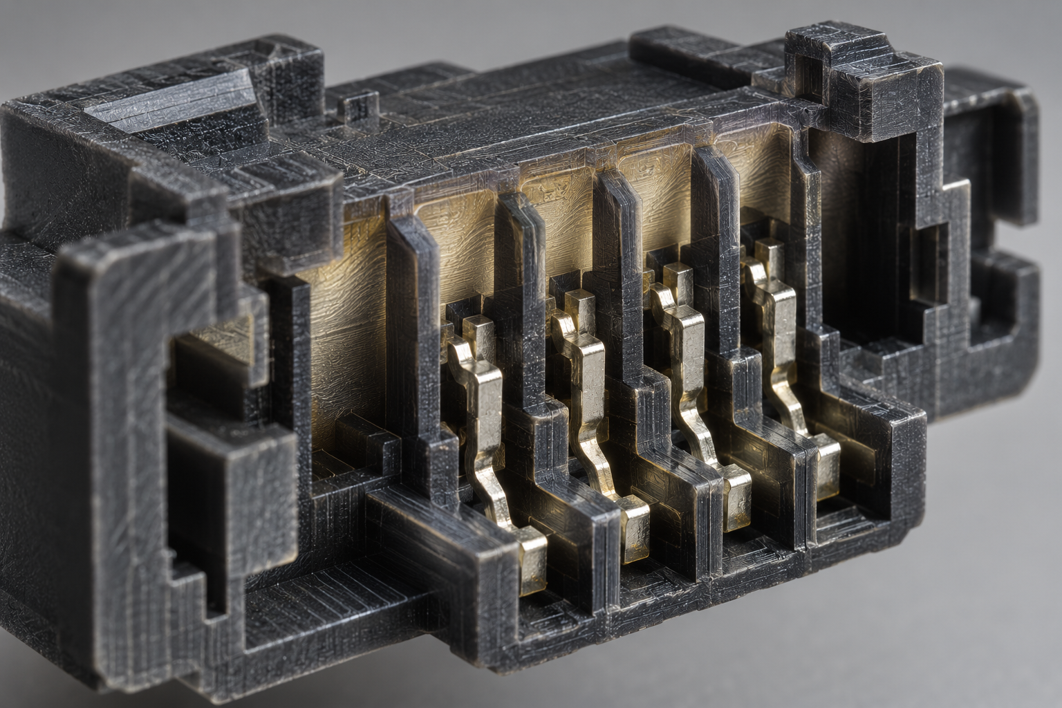
Connectors commonly use high-temperature engineering plastics: LCP, PA9T, PA46, PBT (including glass-fiber/mineral-filled), etc. They are usually chosen to survive reflow soldering — but the same property brings three consequences procurement must watch.
- Shrinkage: Filled materials usually have anisotropic shrinkage, with a considerable difference between flow direction and perpendicular direction. Cavity dimensions can only be calculated together with material and gate plan, not by applying a single-point value from the material data sheet.
- Anisotropy: In fine-pitch (0.4 mm and finer) connectors, terminal positioning posts and thin-wall barriers show directional differences directly as hole position shift and warpage.
- Moisture absorption: PA-type materials change in dimensions and rigidity after absorbing moisture. If batch parts involve long-term storage or hot-humid environments, dimensional judgment must be made under the agreed condition (dry state/conditioned state), otherwise receiving and shipping will each have their own story.
Allocate tolerances first: mold-guaranteed + injection-guaranteed, don't push everything onto injection molding
A common industry practice is to split key dimension tolerances into two segments: the segment the mold can guarantee (cavity dimensions, insert positioning, parting surface fit), and the segment the injection process can guarantee (shrinkage variation, packing, dimensional drift caused by mold temperature). If a key dimension tolerance on the drawing is set within ±0.05 mm but the entire band is assigned to the injection side, you will keep adjusting the machine during trial runs and still not hold it.
The most practical item in a procurement memo: first confirm which dimensions truly affect terminal retention force and insertion/withdrawal. These are the "control dimensions"; the rest can follow general tolerances. In the industry, key dimension tolerances for conventional connector plastic parts often fall in the ±0.05–±0.10 mm range, and fine-pitch, high-precision parts are tighter. This range is only a judgment reference, not a commitment — confirm each item according to the drawing, application, and supplier capability, and write it into the technical agreement.
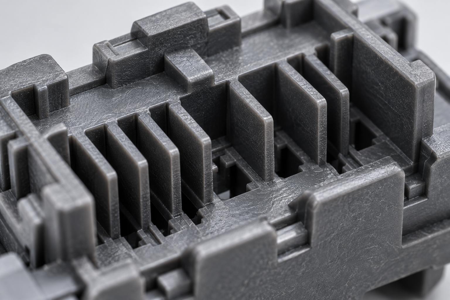
There is another often overlooked point: draft and wall thickness. To fill thin-wall parts, mold temperature and injection speed must be raised, which amplifies shrinkage variation; uneven wall thickness leaves sink marks in thick areas and short shots in thin areas. These should be reviewed at the DFM stage, not revisited after trial molding. If you are still selecting a process route, first compare the applicable boundaries of injection molding capabilities and rapid prototyping. Using CNC or 3D printing to validate terminal positioning at the prototype stage and cutting the mold for mass production is often more economical than cutting the mold directly and learning by trial and error.
Gates, inserts, and parting surfaces: what the mold plan solves for you in advance
In a procurement memo, the mold plan section is the easiest to skip — because the drawing does not show where the gate is or how the parting surface runs. But when connector batch problems occur, more than 70% are related to these three things. Clarifying the following items before signing the mold contract is far less trouble than chasing the supplier to adjust the machine afterward.
Gate location determines where the weld line falls: fine-pitch connectors fear this line most
Precision connector injection-molded parts are usually thin, long, and have small terminal pitch. As the melt travels from the gate to the end, it splits and rejoins when encountering holes, core pins, and terminal slots, forming weld lines at the reunion points. Weld lines are lower in strength and appearance than the bulk material. If one lands exactly at the base of a latch or in the middle of a fine-pitch wall, it will crack with a single pry during assembly.
Therefore gate location is not the mold maker's private business. The reasonable approach is to drive weld lines to non-load-bearing, non-appearance surfaces, and if necessary add overflow wells or adjust mold temperature to make weld lines less visible. A common industry practice is: for fine-pitch connectors, prefer side gates or pin-point gates, with locations determined by terminal layout rather than by mold machining convenience. This requires seeing a gate layout diagram during DFM review, not just verbal confirmation.
Insert positioning repeatability: an extra risk for insert-molded connectors
Connectors with metal terminals or shielding plates are insert molding. Metal parts are positioned by in-mold core pins or fixtures. During injection, high-pressure melt pushes against the metal parts; if support is insufficient, terminals will shift and warp. The acceptance focus here is not whether a single sample part is good, but repositioning accuracy — over 50 consecutive shots, how much does terminal position variation fluctuate.
Referencing common industry practice for insert molding: metal parts are first stamped and formed, then placed into the mold for overmolding, and the mold must allow tolerance absorption for the metal parts. Note this in the procurement memo: request continuous sampling data for insert positioning, not just one beautiful first article.

Parting line, draft, and multi-cavity balance: the invisible thresholds for consistency and appearance
Where the parting line sits determines which surface flash appears on. The mating face and latch face of a connector generally do not allow flash, so the parting line must avoid these areas, or flash must be pushed to non-mating surfaces and then trimmed. The same applies to draft angle: without draft, ejection will cause scuffing, and visible surfaces will show drag marks. A common industry reference is 0.5°–1° draft on visible surfaces, with smaller draft allowed on functional surfaces, confirmed in practice against the drawing and material shrinkage rate.
Multi-cavity molds also require looking at runner balance. The more cavities, the harder it is to fill each cavity consistently, and the greater the dimensional spread. Keep one item in the purchasing memo: require the supplier to provide multi-cavity consistency sampling (for example, comparing key dimensions across the first shot, a middle shot, and the last shot), not just data from the best cavity.
These three points together come down to one sentence: the mold plan is not the supplier's internal matter—it directly determines whether you will be firefighting every day during mass production follow-up. Before signing off on the mold, getting the gate schematic, insert positioning method, parting line, and cavity layout in hand is far more useful than arguing about responsibility afterward. For details involving injection molding capability, you can check the process scope on the injection molding capability page before discussing further.
Mold acceptance: what data purchasing should obtain, rather than just looking at samples
In mold acceptance for precision connector injection molding, the most common pitfall is this: the supplier sends a set of samples, the assembly feel is good, and purchasing signs off. By the time mass production ramps up, terminal pitch starts drifting, insert heights vary, and it is already too late to assign blame. Samples can only prove that "this mold can produce parts on that day"; they cannot prove that "it can still produce parts after a mold change six months later." What purchasing needs at the acceptance stage is data, not feel.
First article full-dimensional report: align the datum first, then the dimensions
The first article inspection (FAI) report is the baseline document for acceptance. The key point is not "complete" but that the dimensional datum must match the drawing. Connector plastic parts often use the terminal hole center, latch face, or parting line as the datum; if the supplier measures using its own fixturing datum, the numbers may look good but are unusable. First look at the report: do the datum symbols correspond to the drawing callouts; second look: are any key dimensions missing. A common industry practice is to list key dimensions (terminal pitch, mating face fit dimensions, insert exposure height) in a separate key dimension table, with measured values and tolerance band margin attached. Confirm specific items against the issued drawing and application, and do not accept vague conclusions like "all qualified."
Capability data and multi-cavity consistency: don't fool a multi-cavity mold with single-cavity samples
If the mold is a 4-cavity or 8-cavity mold, acceptance must include data on the differences between cavities. The usual approach is to take several parts from each cavity, measure the same set of key dimensions, and compare the mean and range of each cavity. A common industry acceptance criterion is: a process capability index Cpk of 1.33 or above for key dimensions is considered relatively stable, 1.0–1.33 is a state requiring close monitoring, and below 1.0 basically cannot be released for mass production. This value is a judgment threshold, not a promise; in practice it is set according to the drawing tolerance band width and application. If the range between cavities exceeds one quarter of the tolerance band, question runner balance and mold temperature uniformity rather than relying on downstream sorting.
Insert positioning repeatability and process window records
For insert connectors with metal terminals or shielding plates, acceptance requires one more piece of data: insert positioning repeatability. Take 20–30 consecutive shots, measure insert exposure height and position offset, and look at the fluctuation range. Problems such as inserts not being pressed fully into place or being washed off position by melt in the mold often cannot be seen at the sample stage and erupt in a concentrated way during mass production. At the same time, obtain the process window record from trial molding—barrel temperature, mold temperature, holding pressure and time, and the upper and lower limits of injection speed. This record is the starting point for troubleshooting when problems arise in future mass production, and also the basis for judging whether the mold has a "wide window." A mold with a narrow window may produce scrap when a new batch of material or a new mold run is used, and purchasing needs to know this in advance.

Passing acceptance does not mean you can relax. Purchasing should archive these pieces of data: FAI report, key dimension capability data, multi-cavity consistency sampling, insert positioning repeatability, and trial molding process window. They also serve as the comparison baseline for subsequent mass production sampling inspections—without a baseline, when dimensional drift appears on the production line, no one can determine whether it is mold wear, a material batch change, or process deviation.
Mass production stage: what stability depends on, and which signals indicate a line stop
In mass production of precision connector injection molding, the real risk is not in the first batch but in the three hundredth batch. A qualified first article only proves that the mold plan makes sense; the mass production stage must prove that the same set of parameters can repeat under material batch changes, mold temperature fluctuations, and equipment wear. What purchasing should watch is not "qualified today" but "will it still be qualified tomorrow."
The process window must be fixed, not re-adjusted every time
The barrel temperature, mold temperature, holding pressure and holding time, injection speed, and cooling time set during trial molding are the baseline for mass production. Adjustments allowed during mass production should be limited to small fine-tuning within the window, rather than re-exploring every time material or shift changes. Require the supplier to write these parameters into the process card and keep them on file, and to perform first article confirmation when changing material batches. Material drying is often overlooked—after materials such as LCP and PA9T absorb moisture, short shots, silver streaks, and dimensional drift appear together, so drying temperature and duration must be fixed and recorded.

On-site criteria for failure modes: short shot, flash, warpage, sink marks
Problems must be identified quickly during mass production. Short shots usually point to insufficient injection, low material temperature, or poor venting; flash is mostly related to insufficient clamping force, parting line wear, or excessive holding pressure; warpage is often caused by uneven mold temperature, unbalanced cooling, or orientation stress from gate location; sink marks are concentrated in thick-wall areas or where holding pressure compensation is insufficient. These judgments are directional, and on-site verification must still be combined with the specific structure.
- Continuous drift of key dimensions: when the same mold cavity trends out of tolerance in the same direction over several consecutive shots, first check whether mold temperature and holding pressure are drifting, and do not directly modify the mold.
- Worsening insert positioning repeatability: when the position distribution of terminals or shielding plates in the plastic part begins to spread, it is most likely insert positioning pin wear or robot placement deviation.
- Batch appearance differences: obvious color difference, gloss, or weld line differences between batches usually point to material batch or drying state changes, not the mold itself.
- Declining multi-cavity consistency: widening dimensional differences between mold cavities point to runner balance or localized cooling abnormalities.
When the above signals appear, the reasonable approach is to first stop the line and confirm whether the process parameters and inspection fixture datum are consistent, then determine whether the problem is material, equipment, or mold. Pursuing it with samples and process records is more effective than arguing afterward. Sampling frequency is usually determined by the production pace and the number of key dimensions; key dimensions should be equipped with dedicated inspection fixtures, avoiding the use of calipers to measure dimensions whose datum itself is unstable.
Sampling inspection and inspection fixtures: only when the datum is right does the data mean anything
The most common mistake in mass production control is that the sampling inspection report does not match the drawing datum. Key dimensions of connector plastic parts often use the terminal datum face or mounting face as the datum; if the inspection fixture locates by the outer shape, the measured offset may only be fixture error. Purchasing should confirm the inspection fixture plan before placing an order, and require the supplier to produce data based on the same datum during mass production. 3D scanning is suitable for reviewing first articles and abnormal parts; it does not replace routine sampling inspection, but it can quickly determine whether the issue is a dimensional problem or a datum problem.
Cost, lead time, and the must-ask checklist before quotation
The most common pitfall for purchasing is pressing the unit price to the lowest before the drawing is even complete. A quotation for precision connector injection molding is essentially folding a pile of boundary conditions into one number: mold structure, cavity count, insert method, material grade, tolerance band, inspection method, and packaging form. If you pressure only one of these, the supplier will recover it elsewhere—reducing cavity count, changing grade, skipping inspection, or simplifying inspection fixtures. Later, during mass production, the cost appears in the form of rework, line stoppage, and sorting, often higher than the unit price saved at the beginning.
So what should be done before quotation is not bargaining, but clarifying the conditions. The checklist below can be pasted directly into an inquiry email and filled in item by item.
Must-ask checklist before quotation: fill in all seven items before discussing price
- Annual usage and batch rhythm: how much is used per year, how many batches, and how much per batch. This item directly determines the cavity count trade-off—a mold plan for 100,000 pieces/year is not the same as one for a 5,000-piece trial production.
- Key dimensions and tolerance bands: which dimensions on the drawing are key, what the tolerances are, and how the datum is marked. Do not give only one overall tolerance; the mold guarantee segment and the injection molding guarantee segment must be discussed separately.
- Appearance standard: whether weld line positions are allowed, where the visible surfaces are, and what the criteria are for sink marks and flow marks. If the appearance standard is not clearly written, samples will always be "still improvable."
- Material grade and class: do not write "high-temperature resistant plastic"; write the specific grade. Once the grade changes, shrinkage rate, mold temperature, and drying conditions all change, and mold dimensions change with them.
- Insert form: whether terminals are pre-embedded, post-inserted, or overmolded; who guarantees insert tolerances. Positioning repeatability for insert connectors must be established as a separate item.
- Certification and traceability requirements: Whether material certificates, batch traceability, and first article report archiving are needed. For production lines with traceability requirements, inspection labor hours and record-keeping costs must be factored into the quote.
- Gauges and delivery form: Whether dedicated gauges are needed and who pays for them; bulk, tape and reel, or tray. The delivery form affects downstream processes and packaging costs.
What actually drives the cost
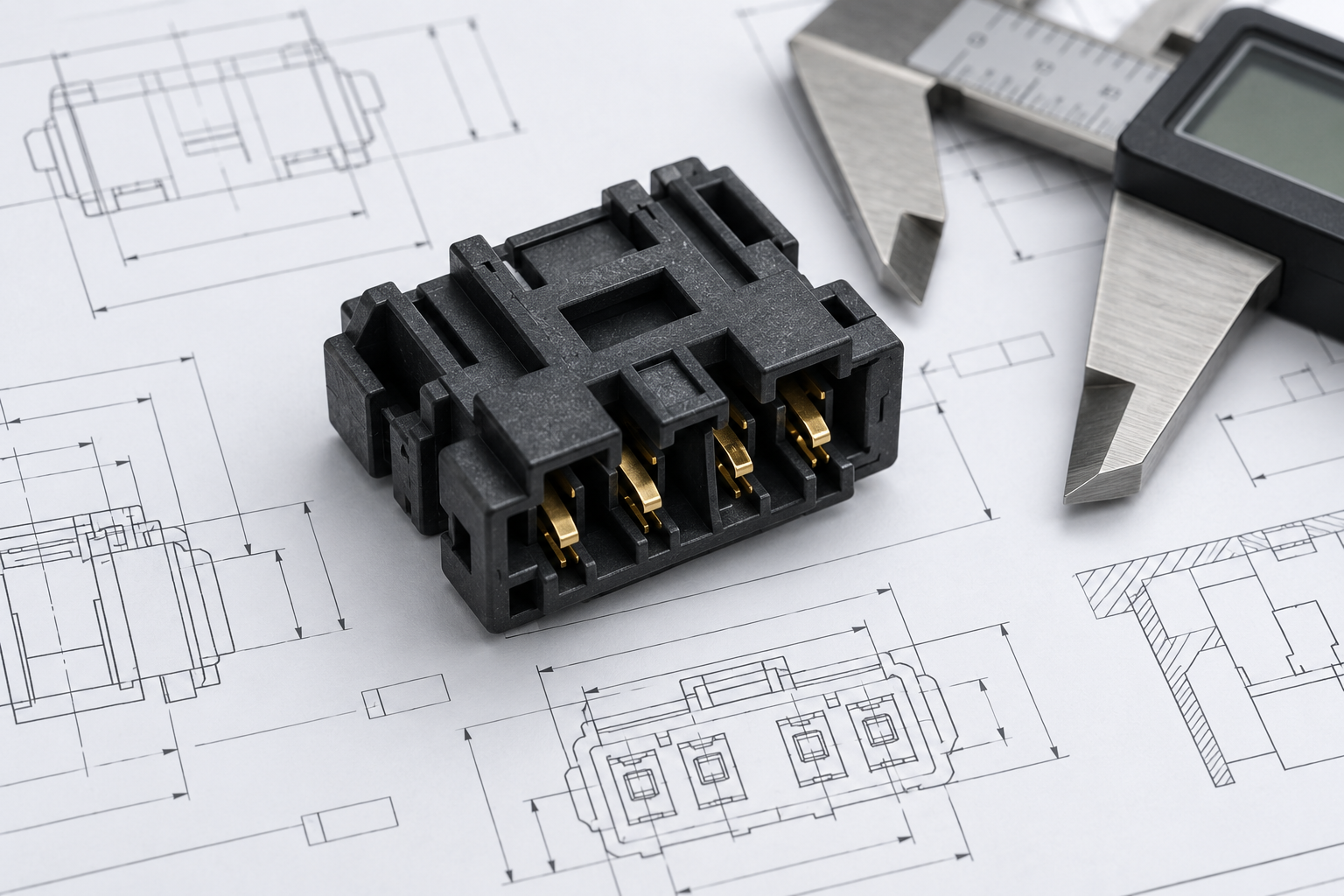
Ranked by impact: mold complexity (parting surface, slides, insert positioning mechanism) > number of cavities and runner balance > material grade (glass fiber/mineral-filled high-temperature engineering plastics are more expensive than general-purpose resins and cause more mold wear) > tolerances and inspection density > delivery form. The number of cavities is a double-edged sword: as cavity count goes up, per-part material and machine time costs go down, but the difficulty of runner balance, multi-cavity consistency, and mold maintenance rises in tandem. In precision connector injection molding, if multi-cavity consistency is not maintained, the machine time saved will be paid back in sorting and scrap.
The common quote structure in the industry is "mold cost + unit price + gauge/first article cost," and some list trial molding and process window records separately. When you receive a quote, first check whether these items are broken out, then check how many sampling inspections are included in the unit price and whether packaging is included. A vague quote usually means there will be add-ons later.
Frequently asked questions (FAQ)
The following points are the ones most often asked during order follow-up and most easily glossed over vaguely at the quoting stage. The answers are given according to the judgments earlier in this article; all specific values are subject to the drawing and the supplier's confirmation.
For precision connector injection molding, which should be determined first: tolerances or material?
Determine the tolerance band allocation first, then the material. This is because tolerance is the sum of two segments: "mold guarantee + injection molding guarantee," and material shrinkage, anisotropy, and moisture absorption directly eat into one of those segments. A common industry practice is: first split the critical dimension tolerances into the mold side and the injection side according to the drawing's application, then select an engineering plastic that can satisfy shrinkage and reflow soldering resistance (such as LCP, PA9T, PBT, PA46, and the like), and finally backfill with trial molding data. Critical dimensions of conventional connector plastic parts are often in the ±0.05–±0.10 mm range, and fine-pitch parts will be tighter—this is a reference for judgment, not a promise, and must be confirmed according to the drawing and application.
During mold acceptance, what data should procurement obtain instead of just looking at samples?
At least four types: a first article full-dimension report (including datum descriptions, and the datums must align with the gauges), capability data for critical dimensions (not single-point pass/fail, but distribution and variation), multi-cavity consistency sampling (essential for multi-cavity molds, to confirm whether there is drift between cavities), and trial molding process window records (usable ranges for mold temperature, holding pressure, and injection speed). For insert connectors, also add insert positioning repeatability data. A qualified sample only means it was qualified at that moment; these data sets are what show whether mass production can hold.
After mass production begins, if dimensions start to drift, where should you check first?
Ranked from largest to smallest impact: first check material batch and drying status (material changes, changes in regrind ratio, and insufficient drying will all alter shrinkage), then check whether the mold temperature and holding pressure window have been altered on the floor to chase output, and then check insert positioning and mold wear. In terms of floor criteria, short shots, flash, warpage, and sink marks often appear before dimensional out-of-tolerance. If critical dimensions drift in one direction over several consecutive shots, or insert positioning is out of tolerance, production should be stopped for review rather than relying on tightened sampling to tough it out.
Why are insert connectors with metal terminals usually quoted higher?
The cost is in positioning and cycle time, not the plastic itself. Inserts must be accurately placed and maintain repeatable positioning before mold closing; molds often require dedicated positioning structures, loading and removal often affect cycle time, and scrap risk is also concentrated in insert misalignment and poor encapsulation. Therefore, insert connectors must have positioning repeatability evaluated separately, and the quote should also state insert incoming material tolerances, loading method, and inspection requirements together; otherwise, once the unit price is pushed down, rework costs later will make up for it.
When asking a supplier to quote precision connector injection molding, what information should be provided?
The more specific, the better: annual usage and batch cadence, critical tolerance items (which dimensions are truly critical and which can be relaxed), appearance standards and allowable surface defects, material grade or performance requirements, whether inserts are needed and their incoming condition, certification and traceability requirements, whether the supplier needs to provide gauges, and packaging and delivery form. Only when the information is complete can quotes be comparable; providing only an outline drawing to push down the unit price usually pushes costs into the trial molding and rework stages. If you need to start the process, you can submit directly through the AI chat quote or classic quote entry points.
Key takeaways
- The success or failure of precision connector injection molding is mostly locked in before the mold is cut: material shrinkage, tolerance band allocation, and gate and insert methods determine batch consistency more than later machine adjustments.
- The smaller the terminal pitch, the more tolerance allocation must lean toward mold and insert precision rather than simply tightening cavity dimensions — first distinguish which dimensions are guaranteed by the mold and which by the injection process.
- Don't just look at full dimensions of sample parts for mold acceptance: obtain the first article report, key dimension Cpk/capability data, insert positioning repeatability, and multi-cavity consistency data.
- Batch stability relies on three things: material lot and drying records,固化 of mold temperature and packing pressure windows, and an inspection plan and gauges aligned with drawing datums.
- Clarify annual volume, key tolerance items, appearance criteria, certification, and traceability requirements all at once before quoting, and you can save two rounds of rework later.



