The process boundaries of machining: first distinguish what milling, turning, grinding, and EDM each handle
Describing machining as just "subtractive manufacturing" is not very useful. What really needs to be judged is: which type of machining process should handle the features on this drawing, and to what precision level, for the cost to be reasonable. The approach in those practical guides in the source is worth learning from—first classify the feature shape, then discuss equipment and parameters.
Milling handles non-rotational features: flat faces, steps, pockets, contours, and hole patterns. A vertical machining center can cover most box-type and plate-type parts in one setup; when three axes are sufficient, there is no need to go to five axes, because the datum error introduced by flipping the part is often more expensive than the operations saved. Turning handles rotational bodies: outer diameters, end faces, inner holes, threads, and grooves; symmetrical parts come out naturally coaxial when turned. Grinding is the finishing layer, needed only for hardened steel, high surface requirements, and strict dimensional stability; grinding ordinary parts is simply a waste of money. EDM and wire EDM handle hard materials and geometric dead corners—corner cleanup, narrow slots, and profiles that are inconvenient to mill after hardening; wire EDM can also cut through holes and outer contours. Drilling, reaming, and tapping belong to hole-making processes; reaming provides dimensional accuracy and hole-wall quality, not positional accuracy—positional accuracy must rely on the preceding locating and drill jigs.
It is recommended to fix the order of judgment: first look at the feature shape → then look at material hardness → and only finally look at the precision level. If the order is reversed and tolerances are quoted right away, it is easy to force an ordinary part into a ground part. Common industry references: ordinary milled flat-face dimensions are mostly in the ±0.05–±0.1 mm range, while fine milling or grinding can reach the ±0.01 mm level; these are only judgment anchors when selecting a process, and whether they can actually be achieved must be confirmed according to the drawing callouts and the factory's actual equipment, tooling, and gauges.
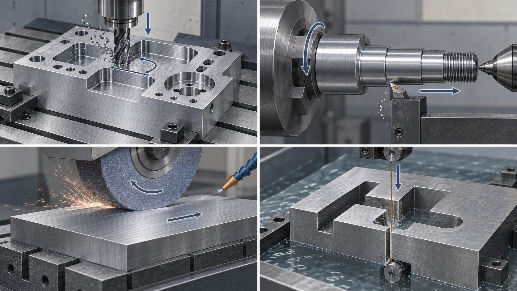
To sum it up in one sentence: choosing a machining process is essentially finding the shortest and most stable process chain for each feature. If something other than a rotational feature can be completed in one milling step, do not split it into turning + grinding; for hardened-material parts that need corner cleanup, do not expect the milling cutter to tough it out. First classify and mark the features on the drawing, then discuss tolerances and quotations—this step cannot be skipped.
Before Sending Out a Drawing: Six Key Items to Review in Machining
Wildly different machining quotes are mostly not because factories are greedy, but because the drawing itself leaves too much room for interpretation. For the same drawing, Factory A quotes based on "as long as it fits," while Factory B quotes based on "full dimensional inspection," and the price difference falls on tolerances, roughness, and inspection methods. The point that truly saves money is not on the shop floor, but before you send the drawing out. The following six items are the places most worth going through one by one when reviewing a machining drawing—none of them is difficult, but missing any one can later become a reason for rework or a price increase.
Whether datums are unified and whether there are datum conflicts
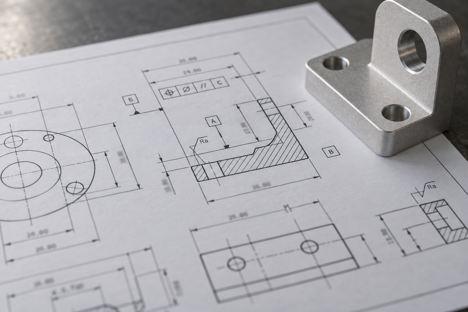
Look at the datum symbols on the drawing: are the design datum, the origin of the dimension callouts, and the face you want the inspector to measure the same one? A common problem is that a hole's position tolerance is based on face A, but the part is assembled by mating on face B, so it ends up offset when installed. On the drawing, confirm that every geometric tolerance frame has a clear datum, and that the datums do not conflict. If two features reference each other as datums (A relative to B, B relative to A), then it is impossible to establish a unified locating face in the process, and inspection will also contradict itself.
Whether critical dimensions are distinguished from general dimensions
If every dimension on a drawing carries two decimal places or a geometric tolerance, that is the same as having no priorities. The process engineer cannot judge which ones must be held and which can be relaxed. On the drawing, confirm that dimensions with fit, motion, or sealing requirements are individually tightened and called out; appearance faces and non-mating faces can be covered by general tolerances (unspecified tolerances). Only then can quotations distinguish primary from secondary, and first-article inspection knows where to measure first.
Whether internal fillet radii are larger than the tool's reachable radius
The internal corners of a pocket will not turn into right angles by themselves. Milling cutters are round, so the internal fillet radius must be at least equal to the tool radius; otherwise the corner can never be cleaned out to the bottom and can only be handled by EDM or hand finishing. On the drawing, confirm that every internal corner has an R value marked, and that the R value is not a casually written R0.5. The smaller the R is specified, the thinner the usable tool, the worse the rigidity, the longer the machining time, and the higher the cost. Where corner cleanup is not functionally required, enlarging the R to the tool's standard radius is the easiest step.
Whether wall thickness and deep-cavity ratios exceed the tool's reach capability
The difficulty of a deep cavity is not the depth itself, but the ratio of tool overhang length to toolholder rigidity. The deeper the cavity and the narrower the opening, the more slender the tool, the more obvious the vibration and tool deflection, and the harder it is to maintain the flatness of the bottom face and the perpendicularity of the side walls. On the drawing, confirm roughly what order of magnitude the ratio of deep-cavity depth to minimum opening width is, and whether a slightly larger internal fillet at the cavity bottom is allowed. If the structure must be deep and narrow, marking an acceptable taper or a split-assembly solution in advance is more cost-effective than reworking afterward.
Whether surface roughness matches the tolerance and is marked on the required faces
Roughness is not a global property. On the same part, a mating face may need Ra 0.8, while Ra 3.2 is enough for a non-mating face; if the entire drawing is uniformly marked Ra 0.8, it is equivalent to making the factory run an extra finishing operation on every face. On the drawing, confirm that the Ra callouts point to specific surfaces or clearly defined ranges, and that they are commensurate with the tolerance grade—a tight tolerance paired with a coarse surface often causes assembly problems in practice. Common industry references are that ordinary milled surfaces are about Ra 1.6–3.2 μm, while fine milling or grinding can reach the Ra 0.4–0.8 μm level; the specific requirement is subject to the drawing and factory confirmation.
Whether the dimensional effects of heat treatment and surface treatment have been allowed for
Quenching and tempering, hardening, nitriding, anodizing, and electroplating all change dimensions or introduce deformation. If the drawing does not state whether dimensions are "after treatment" or "before treatment" for hardening deformation, oxide layer thickness, or coating thickness, the processor can only guess. On the drawing, confirm at which step of the process route the heat treatment is placed (usually after rough machining and before finish machining), which dimensions must still be guaranteed after heat treatment, and whether surface treatment has thickness compensation requirements. If this item is missed, out-of-tolerance dimensions after heat treatment are almost inevitable.
Going through these six items before sending the drawing is not about making the drawing more complicated, but about letting the factory see at a glance which items must be held and which can be relaxed. Spending twenty minutes at the drawing review stage often saves several later rounds of clarification, drawing changes, and rework. If you need to check pricing while going through the process, you can first upload the drawing at the CNC quote entry for a trial calculation, then go back and revise the callouts against the checklist above.
Fixturing and Datums: The Most Common Place Where Machining Accuracy Falls Apart
Single Setup vs. Multiple Setups: Errors Accumulate
Datum Unification: Make the Design, Process, and Inspection Datums Coincide as Much as Possible
Thin walls, slender shapes, irregular profiles: clamping force and support method determine success or failure

Tools, cutting parameters, and surface roughness: Ra is not automatically delivered by tolerance
Just because a tolerance is written on the drawing does not mean surface roughness is guaranteed along with it. Tolerance governs which band the dimension falls into; Ra governs how deep the marks left by the tool tip on the workpiece surface are—the two are determined by completely different links. Ra is mainly determined by the tool, cutting parameters, and the final finishing strategy, while tolerance depends more on machine accuracy, clamping rigidity, and inspection methods. Mixing these two things into one technical requirement is often the source of later rework. A common misconception in machining is that "tight tolerance means naturally good surface," but the opposite is more often true: pressing the feed rate extremely low to hold size actually makes tool deflection and chip buildup at the tool tip more likely, worsening Ra.
Matching tool material to workpiece material is the first step
Cemented carbide is the default choice. Coatings (TiN, TiAlN, AlCrN, etc.) mainly improve wear resistance and high-temperature resistance, and are suitable for continuous cutting of steel and cast iron. Ceramics and CBN are mostly used for hard machining of hardened steel and high-temperature alloys; they are fast but brittle and demand high machine rigidity and stable working conditions. Diamond tools are suitable for aluminum, copper, and non-metals, but wear rapidly on ferrous materials due to affinity, so they are generally not recommended. Choosing the wrong material does not immediately show up as out-of-tolerance dimensions; it first shows up as faster edge wear and slow dimensional drift within a batch. The basis for judgment is: workpiece material, hardness, whether cutting is interrupted, and whether there is heat-treatment allowance requiring hard machining. Specific material grades should be given by the tool supplier according to the working conditions and need not be specified on the drawing.
Feed per tooth and edge radius determine the lower limit of Ra
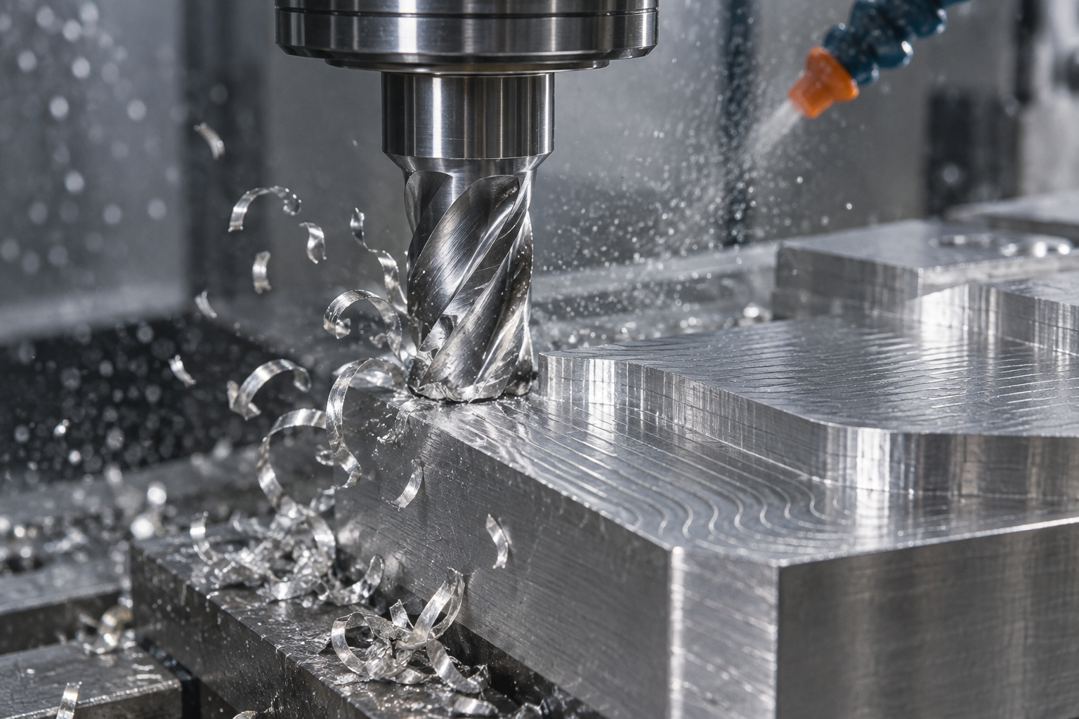
The residual height of a milled surface is theoretically a geometric function of the tool tip corner radius and feed per tooth: the larger the feed, the higher the residual and the worse the Ra; the larger the tool tip corner radius, the smaller the residual at the same feed. This is also why fine milling switches to small-radius, multi-flute tools to press feed per tooth down, rather than simply increasing spindle speed. Finishing allowance is usually 0.1–0.3 mm; too much causes tool crowding, too little cannot remove the hardened layer from the previous cut. Climb milling reduces tool deflection and improves the surface, but requires small screw backlash; conventional milling sometimes gives a more stable surface on old machines, at the cost of faster tool wear.
Common industry reference ranges: ordinary milling Ra is roughly 1.6–3.2 μm, fine milling can reach 0.8–1.6 μm, and grinding or mirror fine milling can reach 0.4–0.8 μm or even lower. These are only reference values for judging magnitude; what can actually be achieved depends on the tool, machine rigidity, material, and the factory's specific process. Be sure to confirm according to the drawing and with the factory, and do not treat it as a basis for quotation or commitment. If the drawing specifies Ra 0.4 for a mating surface and Ra 6.3 for the rest, that is an informative practice; if the entire drawing specifies Ra 0.8, machining cost will be needlessly driven up.
Tool deflection, chatter, and built-up edge: three typical sources of Ra deterioration
Tool deflection comes from insufficient rigidity of the tool or workpiece; the tool is pushed away by cutting force, producing taper or oversized dimensions on the cut surface, especially noticeable during finishing. Chatter appears as regular waviness, often caused by excessive tool overhang or a spindle speed close to the system's natural frequency; adjusting speed or shortening overhang often works faster than changing tools. Built-up edge occurs during low-speed cutting of ductile materials (such as low-carbon steel and aluminum), when chips cold-weld to the tool tip, grow, and then break off, leaving torn textures on the surface and causing Ra to fluctuate. Tool wear is a chronic problem: as the edge becomes rounded, cutting force rises and dimensions drift in one direction within a batch; a good first article does not guarantee a good last article. The countermeasures for these three types of problems are respectively increasing rigidity, avoiding resonance, and adjusting cutting speed and cooling method. These are within the controllable range on the process side, so there is no need to keep changing the drawing.
Tolerance, cost, and inspection: how to set machining tolerances without burning money
Cost-driven tolerance: tighten one step, and the process chain grows several steps
Tolerance bands, fits, and geometric tolerances: don't just stare at the dimension numbers
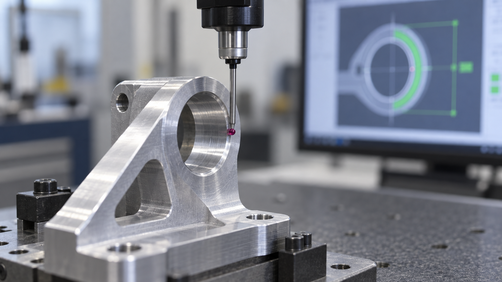
Inspection methods must match batch size and tolerance
Thin walls, deep cavities, and slender parts: the three types of structures most likely to fail in machining
The tolerances, clamping, and tools discussed earlier, when applied to specific parts, cause the most problems in three types of structures. They are not high precision grades, but rather insufficient rigidity—the part itself or the tool moves under cutting force. In machining, the ones that truly fail are often these three types. Below they are broken down by failure mode.
Thin-wall parts: deformation comes from three places
Out-of-tolerance dimensions in thin-wall parts are rarely due to insufficient machine accuracy; they are mostly deformation. There are three sources: cutting force pushing the wall away, clamping force flattening the wall, and residual stress left by the blank or roughing being released after material removal. When the three are superimposed, the part measures correctly during finishing but springs back when the fixture is released.
What design can change: do not make the wall thickness so extreme that the tool chatters at the slightest touch. In industry, keeping aluminum alloy thin walls above 0.8–1.5 mm is commonly easier to machine, and steel parts should be correspondingly thicker; confirm specifics according to the drawing and with the factory. If ribs or process bosses can be left on the inside of the wall, leave them; relax non-mating surfaces and do not mark the entire part to the same tolerance.
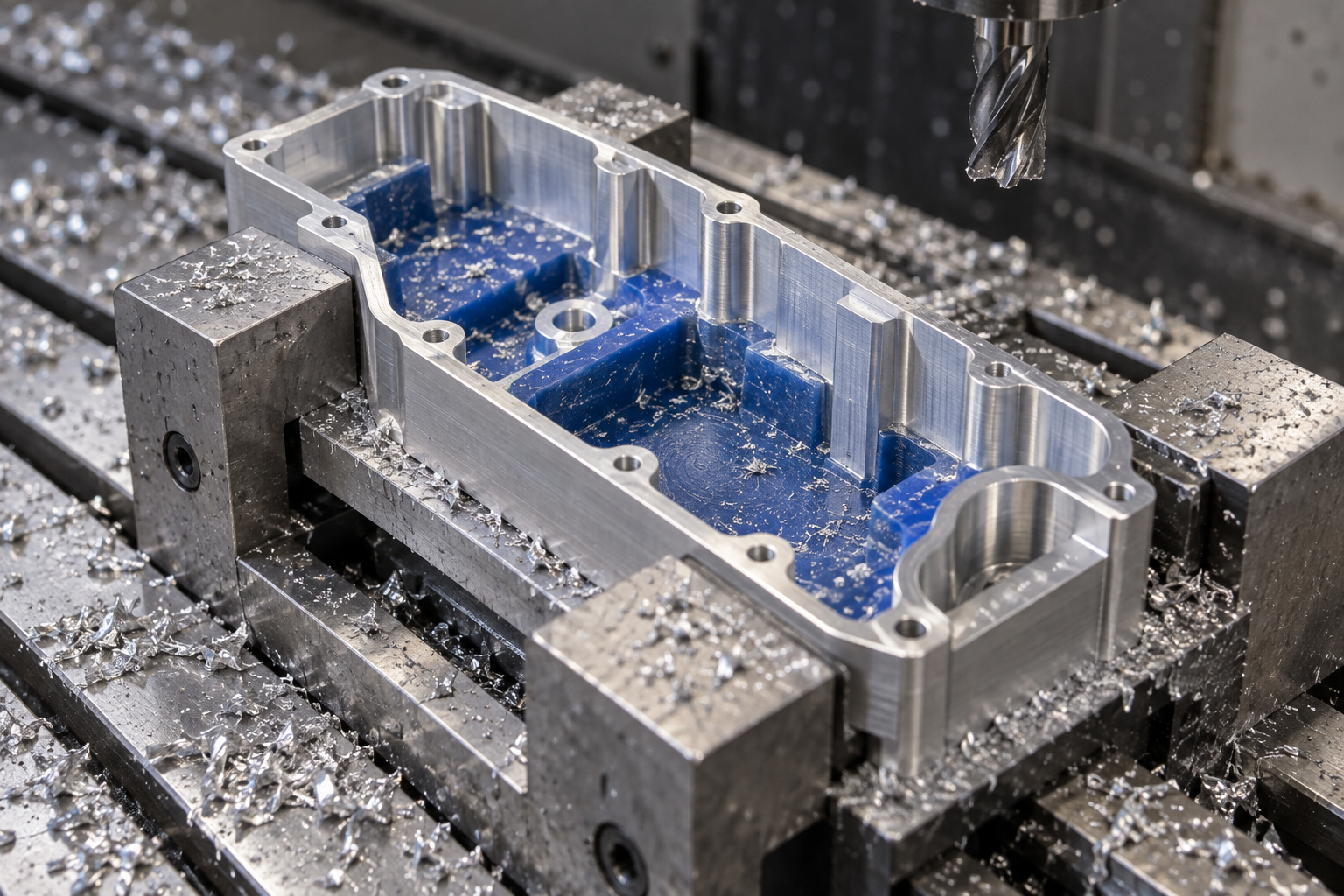
What the process can compensate for: separate roughing and finishing, leave 0.3–0.5 mm allowance in roughing, then relieve stress (aging or annealing) before finishing; remove material symmetrically to avoid continuous cutting on one side; choose clamping points at locations with good rigidity, and use soft jaws or filler supports to reduce elastic deformation; when necessary, use paraffin, low-melting-point alloy, or dedicated supports to hold the cavity before finish milling. These practices do not promise to eliminate deformation; they only press deformation into the tolerance band.
Deep cavities and narrow slots: can the tool reach, and can chips be evacuated?
The problem with deep cavities is not the machine; it is that the tool overhang is too long, causing insufficient rigidity, chatter, and deflection, ruining both dimensions and surface finish. Narrow slots are difficult for chip evacuation; chips clog in the slot and are recut, galling the slot walls and chipping the tool.
What design can change: the internal fillet radius should not be smaller than the minimum tool radius, otherwise it cannot be cleaned properly and can only be done by EDM or hand repair; do not force the depth-to-diameter ratio. In industry, tools with an aspect ratio within 3–4 times are commonly more stable for conventional milling; anything deeper requires a process change, so confirm specifics according to the drawing and with the factory. Leave chip-evacuation space in slot width; do not make it a narrow slit exactly equal to the tool diameter.
What the process can compensate for: layered cutting, helical ramping, high-pressure coolant to flush chips; when using necked or extended-reach tools for deep cavities, reduce feed per tooth; for narrow slots, switch to a tool smaller than the slot width and take two passes, or go straight to EDM or wire cutting. At corner-clearing locations, if the precision requirement isn't high, you can enlarge the radius a bit so milling completes it in one pass, saving an EDM operation.
Slender parts: tool deflection and vibration are the main enemies
For slender shafts and slender rod-type parts, during turning the middle of the workpiece gets bent by cutting forces, forming a barrel shape; milling slender ribs causes chatter, leaving ripples on the surface. No matter how tightly the tolerances are specified for such parts, they can't be made if the process can't keep up.
What the design can change: when the length-to-diameter ratio is too large, consider machining in segments and then joining, or changing to an assembly; allow a process clamping position or a boss for a steady rest in the middle. What the process can compensate for: use a follower rest or steady rest for support during turning; for milling, segment the cuts and use symmetrical tool paths to reduce overhang; lower the feed and raise the speed to avoid the chatter frequency; separate roughing and finishing, with small depth of cut and slow feed in finishing.
The common point of these three types of structures: the problem is rigidity, not precision. When reviewing drawings, first ask "is this part rigid enough to machine"—that's more useful than changing tolerances first. If these types of structures have mating surfaces or sealing requirements, how to set tolerances and surface roughness can be worked out along the earlier line of thinking on gauges and functional tolerances; when the process route is uncertain, sending out the drawing to first confirm machinability is less trouble than just pushing for a lower price.
How materials and heat treatment affect the machining process route
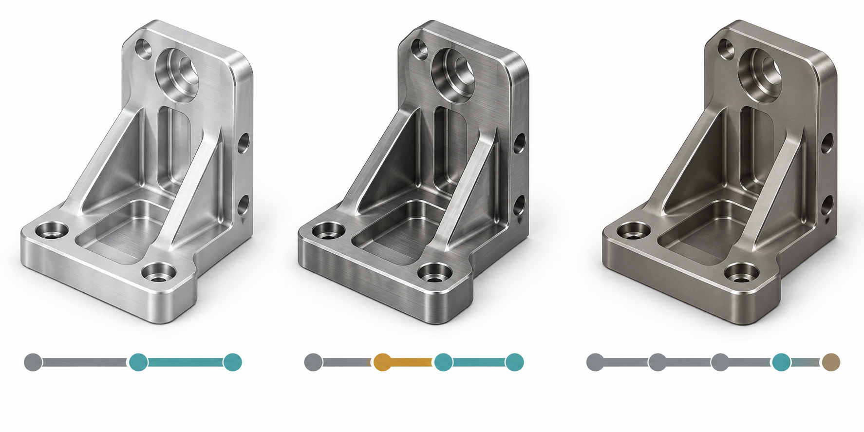
With the same drawing, switching to a different material makes the machining process route completely different—not just the cutting parameters change, but the division of roughing and finishing, the position where heat treatment steps are inserted, and even whether milling can ultimately achieve it all have to be recalculated. When choosing a material, first ask three things: how is its machinability, can it still be machined after heat treatment, and will heat treatment eat up the precision earned by rough machining.
The "temperament" of four common materials in machining
- Aluminum alloys (6061, 7075, etc.): best machinability, speeds can be run high. The trouble is in two points—soft and prone to built-up edge (which smears the surface), and high internal stress, so thin walls or large areas of material removal tend to deform. So aluminum parts often rely on "symmetrical material removal + separating roughing and finishing" to control deformation, rather than clamping harder.
- Stainless steel (304, 316, etc.): obvious work hardening—once the tool stops and rubs at the same spot, the surface layer hardens and the next cut is harder; poor thermal conductivity, heat concentrates at the cutting edge, and the tool wears fast. The countermeasure is to keep cutting continuous, don't let the tool "rub," and use plenty of cutting fluid.
- Titanium alloys: even worse thermal conductivity, heat almost all goes into the tool, easy to burn the tool; high chemical activity, low speed with large feed is safer than high speed. The common industry practice is to lower the speed and increase feed per tooth to carry away as much cutting heat as possible.
- Hardened steel and engineering plastics: hardened steel (such as above HRC 50) is difficult with conventional milling, so mostly hard milling (with tools such as CBN) or grinding or EDM is used; engineering plastics are the opposite—they fear heat, and both cutting heat and clamping force cause thermal deformation and springback, so parameters should lean toward "fast in, fast out, light clamping."
Heat treatment should be inserted after rough machining and before finishing
Common machining questions (FAQ)
The questions below are basically the ones most likely to be asked after the drawing review and quotation. The answers follow the criteria in the previous sections, and specific values still need to be confirmed against the drawing and the factory.
How tight should tolerances actually be on a drawing?
First separate functional surfaces from non-functional surfaces. Only dimensions with mating, motion, or sealing requirements should be tightened; the rest follow general tolerances. In machining, ordinary milling commonly achieves ±0.05~±0.1 mm, and fine milling or grinding can reach the ±0.01 mm level; one step tighter and the process chain has to add grinding or EDM, and both cost and inspection time jump. The criterion: if a dimension has no assembly relationship but is marked ±0.01, it's most likely too tight. For what can actually be achieved, confirm against the drawing and the factory.
Are Ra and dimensional tolerance the same thing?
No. Tolerance governs which range the dimension falls in, while Ra governs the microscopic undulations of the surface. A ±0.05 mm dimension can have a surface of Ra 3.2 μm or Ra 0.8 μm, depending on whether sealing or sliding is needed. Conversely, a low Ra requirement (small value) usually means adding fine milling or grinding operations, but the dimensional tolerance doesn't necessarily tighten along with it. So the two should be specified separately; don't use tolerance to imply the surface.
For the same drawing, why do several machining quotes differ so much?
Common differences come from three places: the fixturing plan (whether special tooling is needed, how many times it's flipped), the length of the process chain (whether grinding or EDM is added), and the inspection method (calipers or CMM, whether special gauges are needed). In addition, batch size affects unit price—tooling amortization for a single piece and for small batches is completely different. When quotes differ a lot, first ask what process route the other party quoted by; that's more useful than directly comparing numbers.
Should the machining process be written on the drawing?
Generally you don't need to specify the concrete process; just write clearly the datum, key dimensions, tolerances, surface requirements, and heat treatment, and let the factory choose the route according to its capabilities. But there are two types of exceptions worth noting: one is positional relationships that must be guaranteed in a single setup, and the other is dimensions that cannot be ground after heat treatment. Writing clear constraints is more useful than writing process names.
For small batches, should I choose machining, or 3D printing or vacuum casting?
It depends on material and precision. For metal parts, or those needing real mechanical properties or mating precision, CNC machining is more reliable; for plastic appearance parts, within a few dozen pieces, not load-bearing, 3D printing or hand-made prototypes/vacuum casting are usually faster and cheaper. For complex structures but quantities reaching hundreds or thousands, with injection-molding-grade plastic, then consider tooling. There's no universal answer; judge by material, batch size, and tolerance together.
Key takeaways
- When choosing a process, first look at feature accessibility: deep cavities, narrow slots, thin walls, and internal fillet radii determine whether milling can cut it in one pass, rather than talking about tolerance numbers first.
- Tolerances are not better the tighter they are marked; cost is usually driven by datums, the number of setups, and whether grinding/EDM is needed, not by the nominal dimension.
- The first risk for thin walls and slender parts is deformation and chatter; separating roughing and finishing, removing material symmetrically, and controlling clamping force are often more effective than switching to a more expensive machine tool.
- Surface roughness and tolerances should be specified separately: Ra is determined by the tool, spindle speed and feed, and whether a finishing pass is added, and it is not automatically satisfied by the tolerance.
- Inspection cost must be planned together with tolerances: the trade-offs among gauges, CMM, first-article inspection, and in-process sampling determine whether this drawing can be produced stably.