What High-Precision Machining Is Really Talking About: First Establish the Precision Ladder
For the same aluminum part, three suppliers all say they "can do high-precision machining," yet their quotes can differ by three times. The difference is not whether the machines are new or old, but that their default precision targets are simply not at the same level. To judge whether a quote is reasonable, you first have to break the word "precision" into a scale that can be aligned.
In the industry, machining is usually divided into three levels according to removal amount, achievable precision, and surface quality: rough machining, precision machining, and ultra-precision machining. Rough machining precision is roughly 0.1mm~0.01mm, with the goal of quickly approaching the shape; precision machining usually falls within 0.01mm~0.5μm, balancing dimensions, geometry, and surface; ultra-precision machining advances toward the nanometer level, and in some cases even approaches the atomic scale. The difference between these three levels is not "doing it a little better," but replacing the entire system of equipment, tooling, environment, and inspection.

Why are the targets so different when all are called machining? Because each level solves a different problem. Rough machining cares about material removal rate and allowance distribution; surface tool marks and dimensional variation are acceptable. Precision machining cares about whether fits, seals, and assembly can be achieved in one pass. Ultra-precision machining cares about functional indicators such as optical wavefront and nanometer-level flatness—being off by a few tens of nanometers can ruin a mirror surface. Once the boundaries of these three levels are clearly drawn, later discussions of IT grades, tolerance zones, surface roughness, and inspection methods have a basis.
One more point is easily overlooked: the precision ladder is not about skipping levels in one direction as better. A bracket that only requires ±0.1mm, if forced to be made to precision machining standards, will cost more and take longer to deliver, without better function. Conversely, if a surface that should be precision machined is released as rough machining, the assembly stage will have to compensate through fitting, shims, or even rework. The starting point for judgment is always the functional requirement, not "the more precise, the more advanced."
IT Grades and Tolerance Zones: Translating "High Precision" into Inspectable Numbers
If the drawing only says "precision machining," the shop cannot start work, and inspection cannot make a judgment. For high-precision machining to be implemented, the first thing is to translate the precision target into measurable, judgeable numbers—this is usually expressed through tolerance zones or IT grades.
IT (International Tolerance) is divided into twenty grades from IT01 to IT18, with smaller values indicating higher precision. It is a general system for expressing tolerance grades: the same IT grade corresponds to different tolerance values in different basic size ranges. The larger the size, the larger the absolute tolerance value for the same IT grade. So when you see "IT7," you must first ask: how large is the basic size? Discussing IT grades without size is as good as not discussing them at all.
IT grade, directly specifying a tolerance zone, or writing only "precision": the difference between three ways of writing it
Writing an IT grade is suitable for batch parts and standard mating surfaces, making it easy to compare with standard tolerance tables and for suppliers to quote processes on the same basis. Directly specifying a tolerance zone (for example, φ20 −0.01/−0.02) is more precise and is often used for one-off parts, non-standard parts, or mating dimensions, without relying on table lookup. Writing only "precision" cannot be inspected—"precision" is an adjective, not a criterion. Replacing it with numbers before delivering the drawing is the most direct step to reducing back-and-forth communication costs.
Another common way of writing it is to give a reference value plus "according to IT grade." In this case, two things must be confirmed: which dimension is the basis, and which grade is being used. Otherwise, the supplier may work to a loose interpretation while inspection judges by a strict interpretation, and that is where disputes arise.
How Tolerance Zone Tightness Affects Machining, Fixturing, and Inspection Costs
Tightening a tolerance zone is not a linear cost change. Tightening by one grade may only mean changing tools or cutting parameters; tightening by another grade often means switching to grinding, increasing the number of setups, controlling workshop temperature, and using higher-precision gauges. Tolerance, fixturing, and inspection are bound together: tighter tolerances require more stable datums, more stable datums require fewer setups, and fewer setups in turn affect the available process route.
A common industry practice is to assign tolerances by functional face level: tighten the faces that truly participate in fitting, sealing, guiding, and locating; loosen non-functional faces (appearance, clearance, cable routing grooves, lightening holes). One tolerance for the entire drawing means spreading the strictest requirement across all faces, which noticeably increases cost and does not help the part's function.
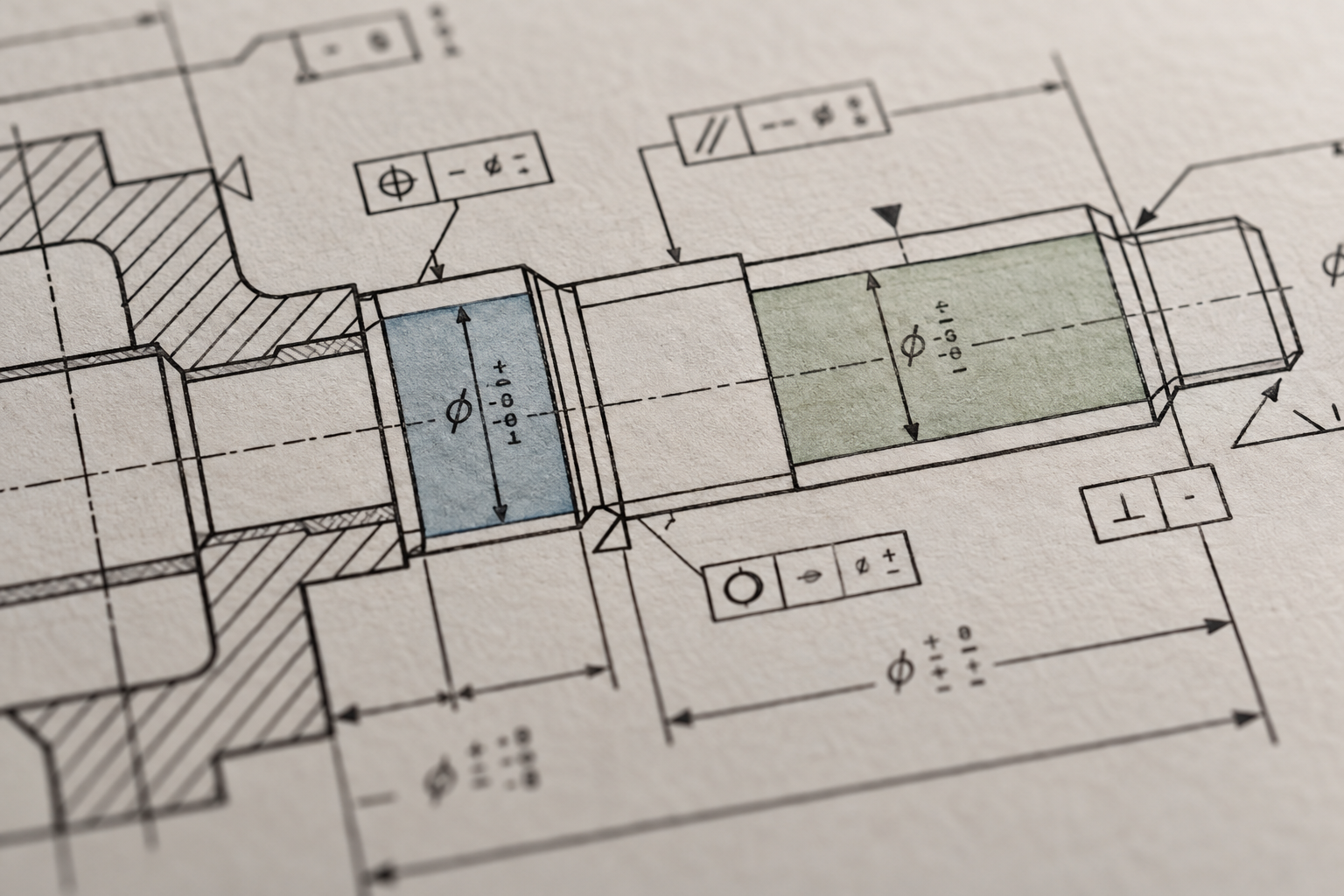
To judge whether a tolerance should be tightened, first ask what function it serves: is it an interference fit or a clearance fit? Is it a locating datum or a clearance? Are there allowances for thermal expansion, assembly sequence, or wear compensation? Once these questions are answered clearly, the tolerance zone can naturally be determined. The cost switch for high-precision machining is often not on the machine tool, but in these few numbers on the drawing.
What Enables Precision Machining to Achieve Micron Level: Equipment, Fixturing, and Thermal Stability
Just because a drawing specifies micron-level tolerances does not mean micron-level precision will automatically be achieved. What separates precision machining from high-precision machining is not a more expensive machine tool, but whether an entire set of conditions holds at the same time: the geometric precision of the machine tool itself, the rigidity chain of the tool and tool holder, whether workpiece fixturing and datums are unified, whether workshop temperature is controlled, and whether cutting parameters match. If any link fails, the final dimensions will drift.
Machine Tool Rigidity and Geometric Precision: The Micron-Level Foundation
The geometric precision of a machine tool determines whether it can stably travel in a straight line or a circle. The straightness of the guideways, the axial and radial runout of the spindle, and the perpendicularity between axes are errors that are directly copied onto the workpiece. In common high-precision machining centers in the industry, spindle radial runout is often controlled to within a few microns; going further up, the positioning precision of the machining center itself approaches the micron level, leaving very little margin for the process.
Rigidity is equally critical. Cutting forces cause slight deformation of the tool and workpiece. If the machine structure is not rigid enough, even light cutting can cause dimensional drift. This is why parts such as thin-walled parts and slender shafts are especially difficult—not because the machine tool is not good enough, but because the workpiece itself yields under cutting forces.
Tools, Tool Holders, and Fixturing: The Most Easily Overlooked Links in the Error Chain
The tool from spindle to tool tip is a series rigid chain. Poor taper contact on the tool holder, excessive tool overhang, or large collet runout will all consume spindle precision. A common industry practice is to use shrink-fit tool holders or hydraulic tool holders instead of ordinary spring collets, specifically to reduce overhang and runout. The tool itself also matters: the cutting edge of an end mill used for finishing must be sharp, and the coating must match the material; otherwise cutting forces rise and tool deflection worsens.
Fixturing is another hidden source of error. The more faces that can be completed in one setup, the smaller the cumulative error; multiple setups must be controlled through unified datums. In actual production, precision parts usually require the datum face to be machined first, with all subsequent operations referencing it, to avoid "changing zero point with every clamping." Vacuum chucks, custom soft jaws, and precision vises are essentially means of reducing deviations introduced by fixturing.

Thermal Stability and Multi-Axis Capability: Environmental Conditions for Micron-Level Machining
For every 1°C increase in a steel part, a 100mm length expands by a little over 1μm. If the temperature difference between the workshop in summer and winter is more than ten degrees, the dimensions will not match. Therefore, precision machining workshops usually need temperature control; a common industry standard is 20°C±2°C or tighter, and ultra-precision scenarios require even more. The machine tool itself also generates heat, and thermal deformation accumulates after the spindle runs continuously for several hours. Warm-up before startup and waiting for thermal equilibrium before first-article inspection are routine operations, not extra steps.
Multi-axis capability determines whether complex geometric shapes can be completed in one setup. Common industry configurations range from 3-axis to 5-axis, and advanced machine tools have even more axes. 5-axis simultaneous machining allows the tool to approach curved surfaces at a more reasonable attitude, reducing surface quality fluctuations caused by the inefficient point contact of ball-nose tools, and also avoids datum errors introduced by multiple flipping setups. Whether to use 5-axis depends on whether the part has continuous curved surfaces, deep cavities, or angled hole systems, not on the idea that more is always better.
In the end, micron-level precision is the combined result of equipment, tooling, fixturing, environment, and inspection. Looking at any single configuration item in isolation is meaningless; the key is whether the error in each link of the entire chain is controlled within a reasonable proportion. To evaluate whether a precision machining plan can be implemented, the equipment and process descriptions in CNC machining capabilities are closer to reality than looking only at a parameter table.
Surface Roughness and Geometric Accuracy: Why Ra Passes but Assembly Still Doesn't Fit
Dimensional tolerance, geometric tolerance, and surface roughness are three independent acceptance languages. Specifying only dimensional tolerances on the drawing and measuring only dimensions during inspection is the most common acceptance gap in high-precision machining—every dimension of the part is within tolerance, yet during assembly it won't compress tightly, leaks, or runs off. The problem is usually not the dimensions, but the geometric shape and surface texture.
What Each of the Three Types of Requirements Governs
Dimensional tolerance governs the size of a feature, such as hole diameter, shaft diameter, or slot width. Geometric tolerance governs shape and positional relationships: straightness, flatness, roundness, cylindricity, parallelism, perpendicularity, coaxiality, position, etc. It constrains whether "the surface itself is straight, whether it is round, whether two surfaces are parallel," independent of size. Surface roughness governs microscopic surface irregularities, commonly expressed as Ra (arithmetic mean deviation) and Rz (maximum profile height). The three cannot substitute for one another: a plane can be fully acceptable in thickness dimension, but bulge 0.02mm in the middle—that is flatness out of tolerance; the same plane can also have good Ra, but with tool marks in a single direction, a sealing ring pressed onto it may still leak.
Two Typical Scenarios: Geometric Out-of-Tolerance and Texture Direction
Scenario one, sealing face. The thickness dimension of a pump body end face is acceptable, but flatness is out of tolerance by 0.015mm; after the bolts are tightened, the gasket is not fully compressed locally, and it leaks under high pressure. What truly determines sealing here is flatness and surface texture, not thickness.
Scenario two, mating surfaces and fatigue. For a shaft and bearing housing fit, Ra meets the requirement, but the turning tool marks are helical; after assembly the actual contact area is smaller, and fretting wear intensifies during operation. For parts under alternating loads, when the tool mark direction is perpendicular to the principal stress direction, it can also easily become a crack initiation point. That is why high-precision machining drawings often specify both an Ra upper limit and a texture direction requirement for critical mating surfaces.
Correspondence Between Roughness and Machining Methods
Different processes can achieve very different surface qualities. The common industry approximations are: turning and milling generally Ra 1.6~3.2μm, fine turning and fine milling can reach about Ra 0.8μm; grinding is usually Ra 0.4~0.8μm, fine grinding can reach Ra 0.1~0.2μm; lapping, honing, and polishing can enter below Ra 0.05μm, and ultra-precision single-point diamond turning for optical surfaces can push toward nanometer-level roughness. These are typical industry ranges, not guaranteed values for any particular factory—the specifics depend on material, tooling, machine condition, and fixturing rigidity, and should be confirmed with the machining provider before deciding.

In terms of callout practice, it is recommended to specify requirements separately for functional surfaces: mating surfaces should be marked with dimensional tolerance, geometric tolerance, and Ra at the same time; non-functional surfaces can be relaxed to general tolerances. One tolerance and one Ra for the entire drawing either wastes money on non-critical surfaces or allows critical surfaces to escape inspection. The measurement sequence is the same: first check whether the datum is unified, then measure dimensions, then verify geometry, and finally measure roughness—if the order is reversed, you may not even trust the numbers you get.
Ultra-Precision Machining: From Microns to Nanometers, When Cutting Is No Longer Enough
Precision machining pushes tolerances down to the micron level, while ultra-precision machining continues further, pushing the target to the nanometer or even atomic scale. Once this step is crossed, the problem shifts from "is the machine accurate enough" to "is the material still willing to be cut by the tool."
What Drives Ultra-Precision Machining Toward Higher Accuracy: On-Machine Compensation and Single-Point Diamond
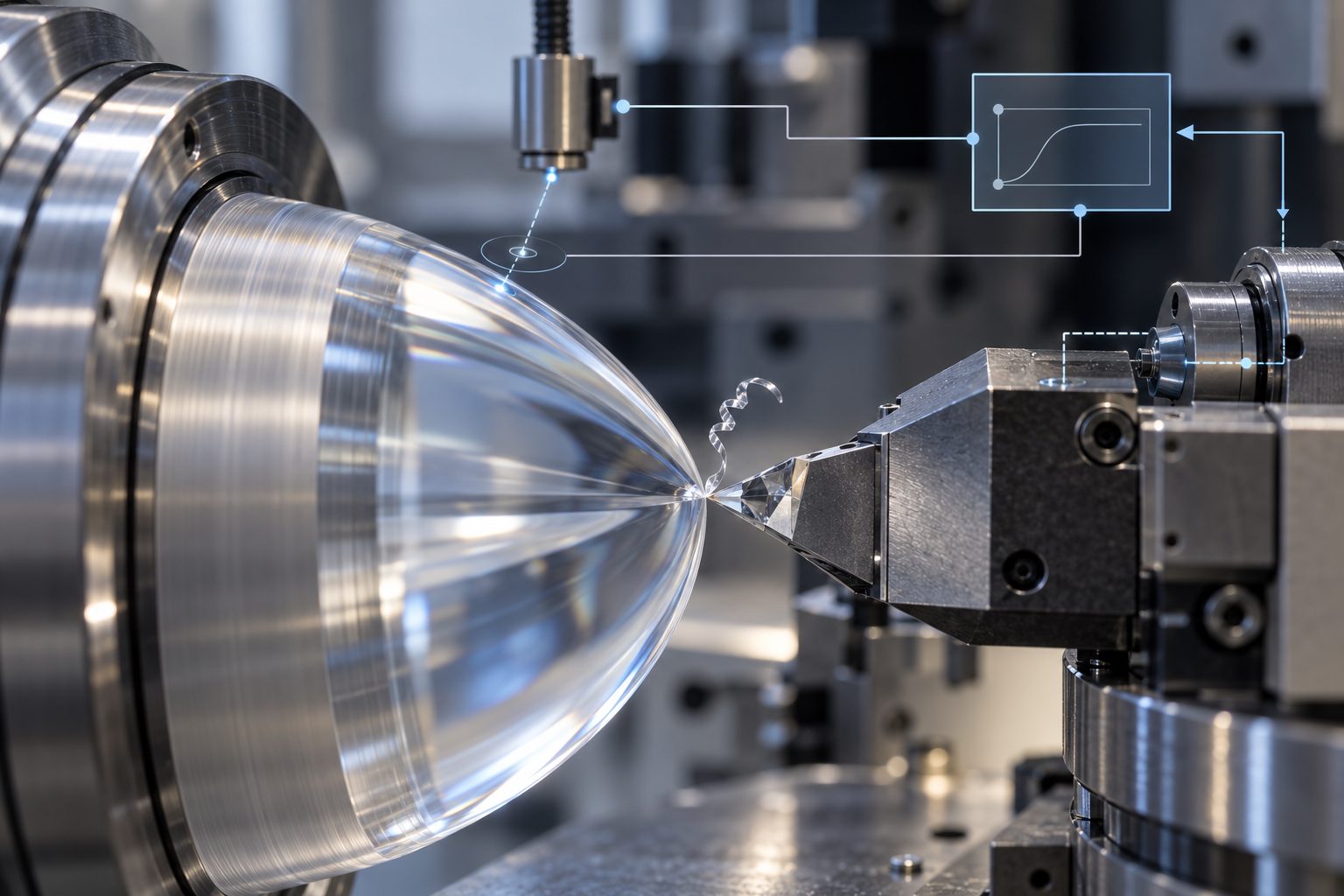
Ultra-precision turning and grinding can enter the nanometer range not by making ordinary machine tools heavier. The classic case is LODTM—a vertical lathe with a maximum machining diameter of about 1.625m, with positioning accuracy on the order of 28nm; with on-machine error compensation, it can machine workpieces over 1m long with straightness error of about ±25nm. This shows several things: accuracy is a closed loop of "measure it and correct it back," not a perfect result produced by static assembly.
The enabling technologies usually include four categories. High-precision position sensors provide real-time feedback on the relative position of the tool tip and workpiece; high-order CNC controllers run the error compensation model in a real-time loop; single-point diamond tools use an extremely sharp edge to achieve micro-removal and reduce deformation caused by cutting forces; and the machine body requires high-rigidity structures and thermal stability design, otherwise room-temperature fluctuations can consume the nanometer budget. Common ultra-precision machining equipment in the industry is mostly aimed at optical aspheric surfaces, freeform surfaces, and precision molds, with machining ranges from tens of millimeters to about 350mm in diameter; specific capabilities are evaluated according to the equipment and workpiece. At this stage of ultra-precision machining, the discussion is no longer "which tool to use," but "where the errors come from and how to eliminate them in real time."
When the Accuracy Target Reaches the Atomic Scale: The Boundary Where Cutting No Longer Applies
The essence of cutting removal is that the tool edge applies local shear to the material, stripping it away as chips. When the target accuracy advances below the nanometer level, even approaching the atomic lattice spacing (about 0.1~0.2nm), this mechanism begins to fail: the edge radius, material grain size, and atomic diffusion between tool and workpiece all make the act of "cutting" itself lose controllability. At this point, the approach shifts to special machining, no longer relying on mechanical shear, but using chemical energy, electrochemical energy, thermal energy, or electrical energy to remove material.
- Mechanochemical polishing: relies on the synergistic action of chemical liquid and abrasive particles to remove material layer by layer from the surface, commonly used for hard brittle crystals and optical surfaces.
- Ion sputtering: bombards the workpiece surface with high-energy ions, knocking out atoms one by one, with removal amounts controllable at the atomic level.
- Ion implantation: implants specific ions into the material surface layer, changing surface composition and properties rather than removing material.
- Electron beam exposure: uses a focused electron beam to write patterns on photoresist, one of the fundamental methods of semiconductor lithography.
- Laser beam machining: uses high-energy-density laser for local removal, cutting, or modification, with the heat-affected zone requiring control.
- Metal evaporation and molecular beam epitaxy: belong to atomic-level addition rather than removal, depositing thin films or single-crystal layers layer by layer in vacuum, used for optical coatings and semiconductor epitaxial wafers.
What these methods have in common is extremely small removal units, high requirements for equipment and environment, and narrow process windows. They are not a substitute for precision machining: in many cases, turning, milling, and grinding are used first to create the shape, and then special machining is used to finish the surface or achieve final smoothness. To decide which route to take, first look at whether the accuracy target falls in the micron or nanometer range, and then look at whether the material is metal, crystal, or thin film.
Inspection and Metrology: Accuracy Is Measured, Not Declared
Marking micron-level tolerances on a drawing does not mean the part can actually be made to micron level; even if it can, that does not mean it can be proven. The final gate of high-precision machining is metrology—using trustworthy instruments, trustworthy datums, and a trustworthy environment to translate "can it be made" into "what does it measure." The root of many acceptance disputes is not the machine tool, but the fact that both parties did not align in advance on "how to measure."
Measurement Uncertainty Must Be Smaller Than the Tolerance: This Is a Hard Threshold
The basic principle of metrology is that the uncertainty of the measurement system itself must be significantly smaller than the tolerance being measured, with a common industry rule of thumb being within 1/3 to 1/5 of the tolerance. The reason is straightforward—if the tolerance band is 10μm and your gauge has 5μm uncertainty, then whether the measurement result falls inside or outside the tolerance is largely a matter of luck, not process capability. At that point, discussing "pass rate" is meaningless; first change the gauge or change the measurement plan.
Conversely, the acceptance logic of high-precision machining should be: first define how to measure, then discuss whether it can be made. If a customer requires a certain dimension to micron level, both parties must first confirm what equipment is used, at what temperature, with which surface as the datum, and how many points are measured. Only after these are confirmed can the supplier judge whether its process window can cover it.
Common Metrology Methods and What Each Measures
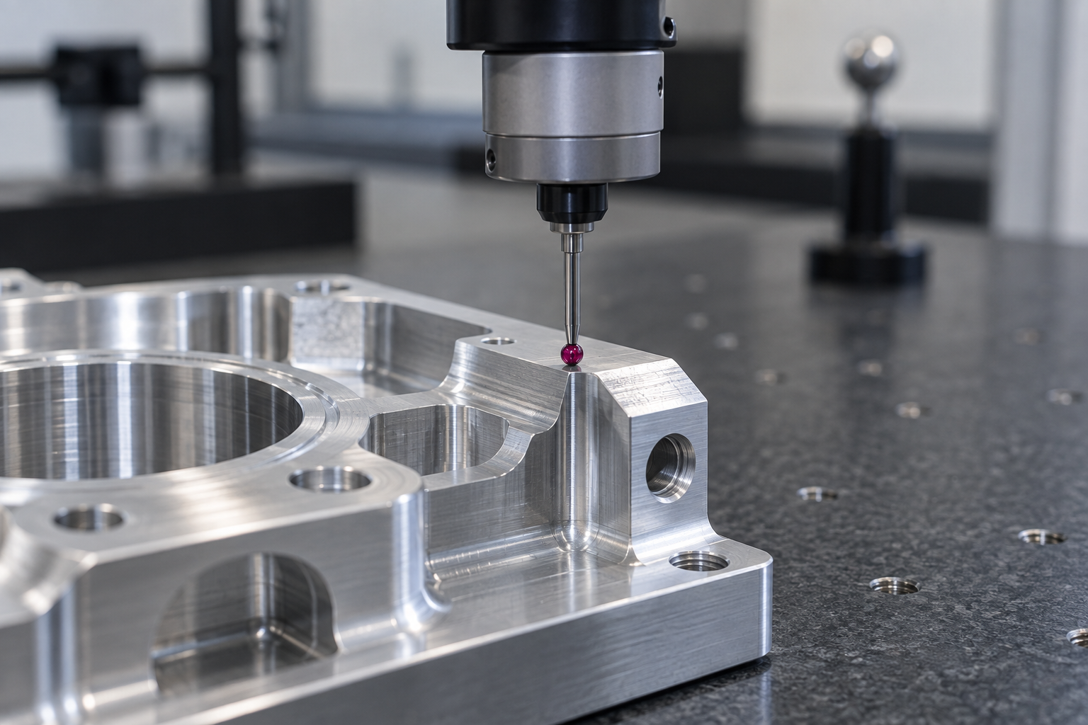
- Coordinate measuring machine (CMM): measures dimensions, position, and most geometric tolerances, and is the mainstay of final inspection for precision parts. Probe diameter, number of measurement points, and fitting method all affect the result, and must be clearly stated in the report.
- Vision measuring machine: suitable for 2D dimensions of thin sheets, stamped parts, and small contours, and fast; limited capability in the depth direction and on highly reflective surfaces.
- Roundness tester / cylindricity tester: specializes in roundness, cylindricity, and coaxiality of rotational parts, and is a key gauge for shafts, sleeves, and bearing seats.
- Roughness tester: measures surface parameters such as Ra and Rz; note that the cutoff wavelength and evaluation length must match the drawing requirements, otherwise the same surface can give different values.
- Laser interferometer: mostly used for machine tool accuracy calibration and long-distance displacement measurement, and also appears in surface shape inspection of optical components.
- 3D scanning: suitable for reverse engineering and full-size deviation comparison, and can quickly provide an overall deviation cloud map; but as a final judgment of precision dimensions, it usually still requires CMM or dedicated gauges for verification.
Datums, temperature, fixturing: three variables that distort micron-level measurement
In precision metrology, when the part itself is fine and the instrument is fine, yet the results don't match up, the problem usually lies in three places.
Datums. The drawing specifies face A as the datum, but during measurement the part is clamped on face B for alignment, so the measured position tolerance is inherently off by a margin. It's best to unify the machining datum, assembly datum, and inspection datum—or at least document the conversion relationship in the process documents.
Temperature. The coefficient of thermal expansion for metals is on the order of 10⁻⁵ /°C. For a 100mm steel part, a 5°C temperature change can shift dimensions by several microns. This is why precision metrology labs typically control temperature around 20°C and require parts to equalize before measurement. A part straight off the machine in the shop and put directly on a CMM may give readings that aren't even in the same order of magnitude as readings taken after equalization.
Fixturing. If the clamping force during measurement is greater than during machining, thin-walled parts get compressed and deformed, measuring as "passing," only to fail once released. Inspection fixturing should simulate the free state or assembly state as closely as possible; when necessary, use dedicated inspection fixtures instead of general-purpose clamps.
First article, in-process sampling, final inspection: what each of the three gates covers
First article inspection confirms whether the process setup is correct, focusing on datums, critical dimensions, and geometric tolerances—usually a full-dimensional inspection or full measurement of critical dimensions. In-process sampling watches for stability—slow drift from tool wear, thermal drift, and fixturing repeatability—and scheduled sampling of a few critical dimensions is enough to spot trends. Final inspection is the last gate before shipment, judging each item against the drawing requirements and issuing a report.
For high-precision machining, these three gates are not optional. Skip the first article, and the risk of a whole batch being scrapped multiplies immediately; without in-process sampling, by the time final inspection catches a problem, a whole batch has already been made; if the final inspection report doesn't clearly state the measurement conditions, the customer's re-measurement won't match, and the cost of rework and disputes ends up higher than the machining itself. Metrology is not an appendage to machining—it is the precondition for precision to be recognized.
Process consistency and DFM: the real cost switch in precision machining
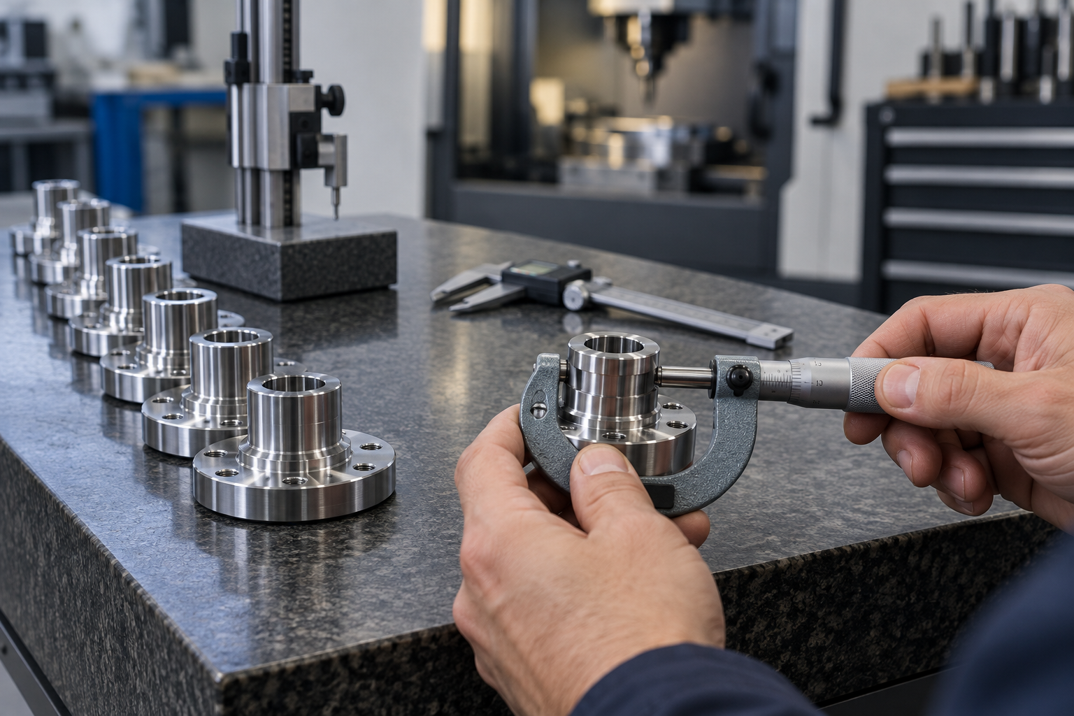
Extreme precision is a spec sheet number; consistency is cash on the production line. Same machine, same tool—today it holds ±0.005 mm, tomorrow ±0.012 mm, and the buyer has to add inspection, add inventory, add rework budget. The commercial value of high-precision machining isn't in how extreme a single part can be, but whether from part 1 to part 1000, dimensions, geometry, and surface roughness all fall within the same distribution band.
Why consistency is a cost switch, not a quality slogan
Consistency delivers four quantifiable returns: first, stable process capability means that after the first article passes, in-process sampling suffices—no need for 100% inspection; second, rework and scrap decrease, especially for fixturing-sensitive parts like thin walls and deep cavities; third, tool wear becomes predictable, so tool changes follow tool life rather than feel, reducing chipping and dimensional drift; fourth, the process is replicable—new operators can start with frozen parameters and inspection fixture procedures, shortening training time. A common industry practice is to include the process capability index (Cpk) of critical dimensions in supplier evaluation, rather than looking only at single-part inspection reports—the specific thresholds are agreed between procurement and the supplier in the contract.
Poor consistency is often not because the machine lacks precision, but because the fixturing plan, cutting parameters, cooling method, and ambient temperature haven't been frozen. For example, if the same batch of parts is clamped in two separate setups and the datum face has burrs or residual chips, the parallelism of the second operation will scatter. Unifying datums, deburring, cleaning, and alignment into a process card is more effective than buying a more expensive machine.
DFM and early collaboration: costs diverge at the drawing stage
Most of the cost curve of high-precision machining is already determined when the drawing is finalized. Early supplier involvement can fix several expensive habits: first, applying one tight tolerance across the entire drawing, forcing even non-functional faces onto grinding machines or wire EDM; second, inconsistent datums requiring multiple setups, driving up both cumulative error and labor hours; third, deep cavities, narrow slots, and sharp internal corners beyond tool reach, forcing EDM or design changes; fourth, thin-walled parts without fillets or ribs, causing chatter during machining and distortion during subsequent heat treatment; fifth, material and heat treatment sequence undefined, only to discover after rough machining that stress relief is needed, and dimensions shift again.
- Unified datums: use one datum face across as many operations as possible to reduce repeated alignment.
- Tolerance tiering: functional faces get tolerances per fit requirements, non-functional faces are relaxed to machinable levels—don't apply one tolerance across the whole drawing.
- Fillets and tool accessibility: specify internal corner fillet radii, avoiding sharp corners smaller than standard tool radii.
- Thin walls and deep cavities: state wall thickness and depth-to-diameter ratio upfront; if necessary, split the part or change the structure.
- Heat treatment and surface treatment sequence: clarify the order of rough machining, stress relief, finish machining, and surface treatment.
These aren't about making design accommodate machining, but about spending the precision budget where it actually affects function. The payoff of early collaboration is direct: fewer late-stage mold changes, process changes, and rush rework, and more predictable lead times. As for whether a specific part is worth a DFM review, you can start by asking one question: is this tolerance a functional requirement, or a habitual annotation? The answer often saves an entire operation. If you already have a drawing, you can run a quick manufacturability assessment through AI chat quoting, then decide whether to adjust the tolerance allocation.
Typical application scenarios: how optics, semiconductors, medical, and aerospace choose precision grades
Optical parts: form and roughness determine the grade, often relying on grinding and polishing rather than pure cutting
Semiconductors and vacuum chambers: dimensions aren't the hardest part—cleanliness and stability are
Medical implants and surgical instruments: small size, high surface quality, traceability
Aerospace structural parts and precision molds: hard-to-cut materials, complex structures—relying on multi-axis and process routing
Different materials, different removal mechanisms—parameters must be locked into CAD/CAM in advance
Frequently asked questions
The questions below are the judgment points where people most often get stuck after reading the "precision ladder" above—they aren't generic company Q&A, but revolve around high-precision machining itself: how IT grades map onto drawings, how micron tolerances are accepted, when to switch processes for ultra-precision, and at what stage DFM should step in.
If the drawing only says "high-precision machining" without specifying IT grade and tolerance band, how does a supplier quote?
It's impossible to quote accurately. IT grades (IT01–IT18, where a smaller number means higher precision) and tolerance zones are coordinates on the precision ladder. Without those coordinates, the supplier can only estimate using the most conservative process—which usually drives the cost up, or they simply quote it as ordinary precision machining, and the final delivery doesn't match.
A common industry practice is: specify tolerances and geometric requirements separately for functional surfaces, and relax them for non-functional surfaces; the approach of applying a single tolerance across the entire drawing often inflates the quote and causes inspection to lose focus. For your specific part, it's recommended to provide the key dimensions, datums, and surface roughness together before requesting a quote.
When precision machining reaches the micron level, is it achieved by the machine tool itself, or by the process and inspection?
It's a combined effort, not a single piece of equipment. Machine rigidity and geometric accuracy, spindle and guideway condition, tool and toolholder systems, fixturing and datum consistency, and workshop temperature and thermal deformation all eat into the precision margin. In terms of multi-axis range, 3-axis to 5-axis is common in the industry, and advanced machine tools can have more, but more axes doesn't mean higher precision.
More critically: first define how you'll measure it, then discuss whether it can be made. Measurement uncertainty must be less than a reasonable proportion of the tolerance, otherwise the measurement result itself is unreliable. So micron-level delivery is usually the product of equipment + process + environment + inspection controlled together.
The dimensions are within tolerance, so why does assembly still not go smoothly?
Because dimensional tolerances, geometric tolerances (straightness, flatness, roundness, coaxiality), and surface roughness Ra/Rz are three independent categories of requirements and cannot substitute for one another. Dimensions may pass but flatness may be out of tolerance, and a sealing surface may leak; Ra may meet spec but the tool mark direction may be wrong, affecting fit and fatigue life.
When annotating, it's recommended to give all three categories—dimensional, geometric, and surface—at the same time, and to specify which surfaces are functional surfaces. A drawing that only specifies dimensions leaves the geometric and surface risks to the assembly floor.
When is ordinary precision machining not enough, and ultra-precision machining becomes necessary?
It depends on which level of the ladder the precision target falls on. Precision machining is usually at the micron level (commonly around 0.01mm~0.5μm in the industry), and pushing further toward the nanometer or even atomic scale means the cutting removal mechanism no longer applies—the atomic lattice spacing is about 0.1~0.2nm, and a tool cannot stably "cut" to that order of magnitude.
At this point you turn to special machining methods such as mechanochemical polishing, ion beams, electron beam exposure, and laser beam machining, and rely on high-precision position sensors, high-order CNC controllers, and online error compensation. Whether you must go this far depends on the real surface and form requirements of applications such as optics and semiconductors, so it's recommended to first do a process route evaluation before deciding.
In a precision machining project, when should DFM get involved?
The earlier the better, ideally before the drawing is frozen. Datum consistency, reducing the number of setups, avoiding overly tight tolerances, machinability of deep cavities and thin walls, fillets and tool accessibility, and material and heat treatment sequence—these determine cost at the drawing stage, and changing them later often means reworking the process or even modifying the mold.
Early supplier involvement can reduce complexity and cut rework. Predictable lead times from process consistency, and extended tool and equipment life, are also planted at this stage. How much can be optimized specifically needs to be looked at together with the part geometry and batch size.
Key takeaways
- Precision has a ladder: rough machining is often at the 0.1mm~0.01mm level, precision machining can reach 0.01mm~0.5μm, and ultra-precision machining advances toward the nanometer and even atomic scale. To judge requirements, first locate which level you are at.
- IT grades (IT01–IT18) are the tool that translates "precision" into inspectable tolerances. Writing an IT grade on a drawing or directly specifying a tolerance zone is far more useful than writing "high precision."
- Ultra-precision machining is not just about making the machine tool more accurate; it also depends on high rigidity, thermally stable structures, high-precision position sensors, online error compensation, and single-point diamond tools. When cutting can no longer remove material, it shifts to special machining methods such as mechanochemical polishing, ion beams, electron beams, and laser beams.
- Process consistency (repeatable dimensions and surfaces) determines the commercial value of precision machining: it affects rework rates, delivery predictability, and inspection costs, not just the extreme precision of a single part.
- Most of the cost of precision machining is set at the drawing stage: datums, tolerance zones, surface roughness, materials, and inspection methods should be clarified during DFM, which is more economical than trying to compensate through machining after the fact.