The hot topics in precision manufacturing machining are actually three process pressures rising at the same time
Ultra-precision optical elements: the process in the hot topics that is hardest to summarize with a "tolerance number"
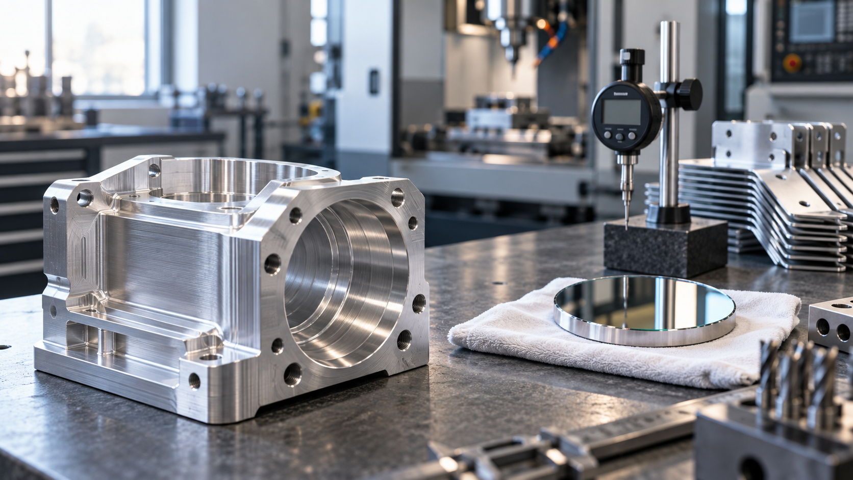
When discussing recent hot topics, ultra-precision optical elements are always used as an example, but they are also the process most easily muddled by a single sentence. Procurement or structural engineers often write requirements as "figure PV≤λ/4, Ra≤5 nm," thinking that giving a tolerance number is enough. In the workshop, these three quantities are separate: figure error governs the overall shape of the curved surface, surface roughness governs local micro-roughness, and subsurface damage governs the invisible cracks and stress beneath the polished layer. The three are independent yet constrain each other—to reduce figure error, polishing time may need to be extended, which in turn damages edge roughness and subsurface quality.
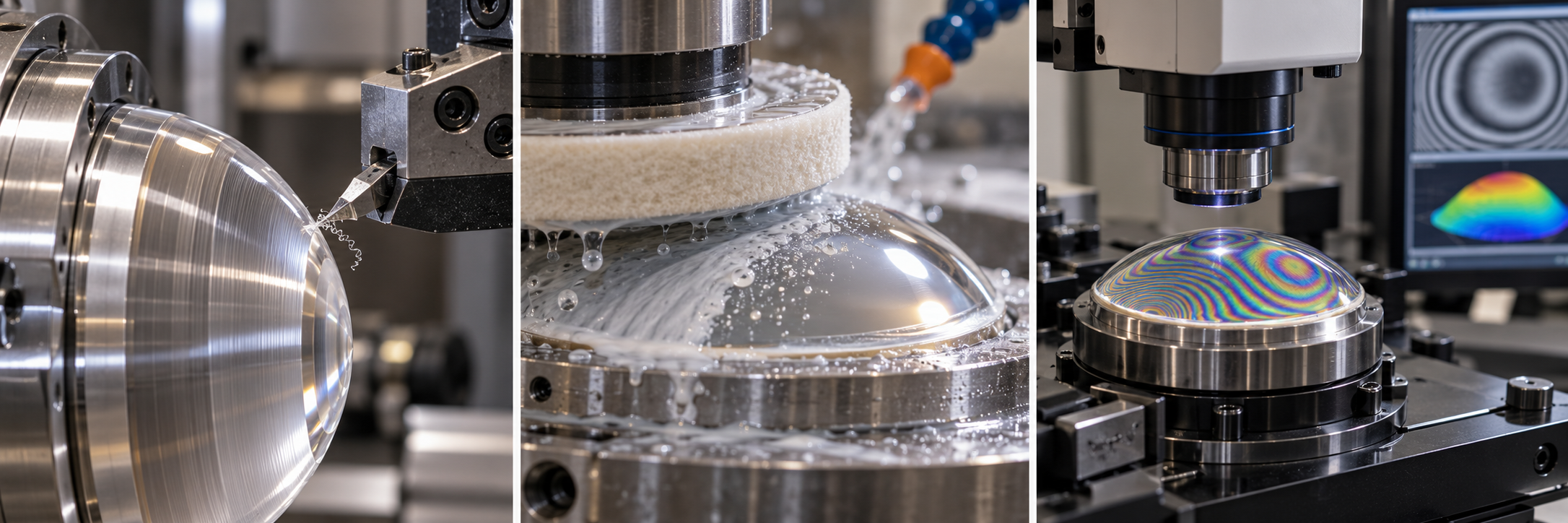
Therefore optical parts cannot be quoted with a dimensional tolerance in the same way as mechanical parts. Common industry routes fall roughly into several categories: single-point diamond turning is suitable for machinable materials such as infrared crystals, aspheres, and metal mirrors, and can form directly, but leaves tool marks on the surface and usually still requires subsequent polishing; traditional grinding and polishing is suitable for visible-light glass and can achieve good figure, but depends on tooling and manual experience; deterministic polishing methods such as magnetorheological finishing and ion beam figuring are used for final figure correction, have high equipment thresholds, and are generally applied to critical surfaces. These are common industry practices and do not mean a particular factory can definitely do them; specifics must be confirmed according to drawings and samples.
Inspection methods must be determined at the quoting stage, otherwise everything afterward becomes argument. Figure is measured by interferometer, roughness and local topography by white-light interferometry or atomic force microscopy, and subsurface damage is often judged indirectly by acid etching or scattering methods. Many optical parts get stuck in the end not because machining cannot produce them, but because at acceptance the two sides have not aligned on "which machine, what aperture, what environment." It is recommended to ask four things clearly when requesting a quote: whether the material is optical glass or crystal, aperture and radius of curvature, whether subsequent polishing is allowed, and the permitted inspection method and sampling ratio.
Ramp-up of new energy vehicle parts: consistency in precision manufacturing machining is harder than single-piece precision
First-piece qualification does not equal batch stability: thermal deformation and repeated fixturing positioning
SPC, sampling frequency, and the logic for choosing gauges
Micro-holes, thin walls, and deep cavities: how structural limits in turn rewrite process and tolerances
In the recent hot topics of the precision manufacturing machining industry, changes in part structures are faster than changes in materials. Downstream is making heat dissipation channels, fuel injection holes, and sensor cavities smaller, thinner, and deeper, all behind the same thing: the design side has compressed functional space to the limit and shifted the pressure of accessibility to the machining side. If such parts follow the conventional order of "first set tolerances, then find a process," quoting and actual machining often do not match. A more reasonable order is to first judge feature accessibility, then go back and set the tolerance band.
Micro-holes: once the length-to-diameter ratio exceeds 5 times, tool breakage and chip evacuation begin to dominate tolerances
Micro-holes usually refer to holes on the order of 0.1–1 mm in diameter. When drilling, what really causes trouble is not hole diameter precision but length-to-diameter ratio. A common industry empirical range is: within a length-to-diameter ratio of 5 times, ordinary carbide micro-drills can still evacuate chips stably; after exceeding 8–10 times, the probability of poor chip evacuation, drill breakage, and hole-wall tearing rises significantly, requiring peck drilling cycles, high-pressure internal cooling, or EDM/laser drilling. Hole diameter tolerance itself is often not the bottleneck at this level; position tolerance and hole-axis straightness are. If the drawing tightens micro-hole position tolerance very much but allows subsequent reaming or grinding, the cost structure will be completely different. Such criteria need to be confirmed according to drawings and samples, and cannot be judged only by the hole diameter number.
Thin walls: tool deflection and chatter make "giving tolerances according to the drawing" ineffective
The trouble with thin-wall parts (common wall thickness 0.5–2 mm) is that cutting force directly pushes the wall away. The drawing specifies free-state dimensions, but during machining they are affected by clamping force and cutting force, spring back after release, and measured values often deviate. There are three common industry responses: first, leave process bosses or auxiliary supports and mill them off at the end; second, use layered light cutting and control feed per tooth, sacrificing takt time for stability; third, rough first and finish later, with stress relief arranged between roughing and finishing. It should be noted that for thin-wall parts, tolerances cannot be judged only by the numerical value; it is also necessary to ask whether the datum is in the free state or clamped state, and whether inspection is performed with fixturing. The same ±0.05 mm marking may mean a qualified part in the clamped state is out of tolerance by a factor of two in the free state. For such parts, it is recommended to state before quoting whether process bosses and auxiliary supports are allowed.
Deep cavities: each doubling of tool overhang reduces rigidity by more than a factor of two
The core conflict in deep-cavity parts (where the ratio of cavity depth to tool diameter exceeds 4–5 times) is tool overhang. The longer the overhang, the worse the tool rigidity, and during cutting it easily leads to tool deflection and chatter marks, while surface roughness and dimensional consistency both deteriorate. The conventional approach is to use an extended holder with small depth of cut and high spindle speed, or switch to EDM or five-axis trochoidal milling to reduce overhang. If both the bottom face and side walls of a deep cavity require relatively high roughness at the same time, it often needs to be split into two operations and two setups, and the repeat positioning accuracy of the setup then becomes a new source of error. One point about deep-cavity parts in precision manufacturing that is often underestimated: the cavity depth tolerance given on the drawing is actually determined by the tool's reachable depth and chip evacuation conditions, not by the machine tool's positioning accuracy.
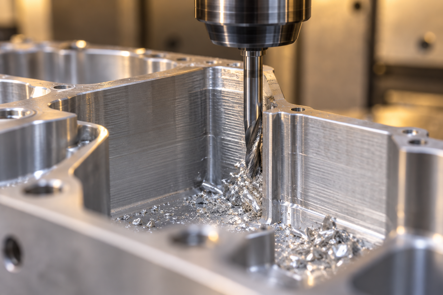
These three types of structures share one thing in common: they turn "what tolerance should be specified" from a design question into a process question. For micro-holes, look at the aspect ratio and chip evacuation; for thin walls, look at clamping and springback; for deep cavities, look at overhang and reachable depth. The trend in hot topics is for structures to continue moving toward extremes, so before quoting, clarify the accessibility of these features first—it is less troublesome than arguing afterward about who is responsible for out-of-tolerance parts.
From drawing to quote: five pieces of information that must be locked down before precision manufacturing
1. Tolerance zones and datum systems: ask about the datum first, then discuss the numbers
2. Critical features and non-critical surfaces: cost hides in this distinction
3. Clamping surfaces and process bosses: whether they are allowed directly determines whether the part can be made
4. Deburring and chamfering: writing it clearly is cheaper than arguing afterward
5. Inspection method and acceptance criteria: the inspection plan must align with the machining datum
How to choose the process route: the division of labor among CNC, vacuum casting, injection molding, and sheet metal under the same hot topic
The phrase "process diversification" often appears in hot topics, but on the shop floor it comes down to one action: determine the route according to three things—quantity, structure, and material. The same drawing going through different processes at different stages is normal division of labor, not compromise.
Segment by quantity: one piece, dozens, hundreds, tens of thousands
For one-off and validation parts, prioritize CNC machining or 3D printing. The former obtains dimensions and fits, while the latter obtains shape and assembly interference checks; neither requires tooling, and the cost of changing the drawing is low. For dozens to hundreds of pieces, and if they are appearance parts or need a feel close to mass production, use rapid tooling/vacuum casting—silicone molds have limited life, and in the industry a set of molds commonly makes on the order of dozens of pieces; the specific number of copies possible must be confirmed according to structural depth and demolding difficulty.
After the structure is finalized and annual usage stabilizes, switch to injection molding. The switch point is not "the number of pieces is large enough," but whether the mold cost can be amortized and whether material performance must use engineering plastic itself. For plate-type parts, enclosure parts, and bracket-type parts, prioritize sheet metal; the cost structure of bending and welding is completely different from machining, and using CNC to mill a 2 mm sheet shell is usually the wrong route.
The three accounts that really need to be calculated at the switch point
The first is mold cost amortization: vacuum casting has a high unit price and low mold cost, while injection molding is the opposite; the crossover point depends on annual usage and mold life, not a fixed number of pieces. The second is surface treatment consistency: the feel and color difference of vacuum-cast parts fluctuate between batches, and before scaling up appearance parts, confirm whether subsequent painting or electroplating can cover it. The third is material performance differences: vacuum casting commonly uses polyurethane-type materials, whose toughness and temperature resistance are not the same as injection-molded ABS, PC, or PA, so load-bearing parts should not be directly substituted.
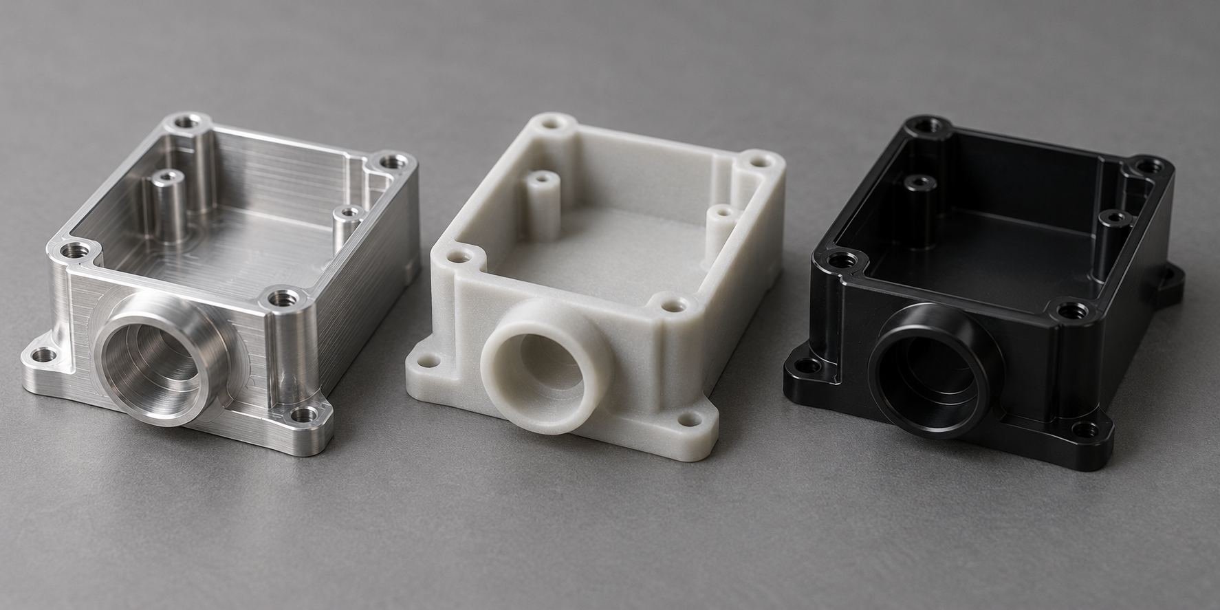
The judgment chain can be simplified into one sentence: at the validation stage, look at freedom to change the drawing; at small batch, look at the proportion of mold cost; at scale-up, look at consistency cost. When quoting, provide annual usage, stage, and appearance requirements together, and route recommendations become meaningful.
Inspection and data closed loop: the underestimated precision manufacturing capability in hot topics
First article, in-process, and final inspection have different roles and cannot replace each other
3D scanning and CMM: not a substitute relationship, but a division of labor
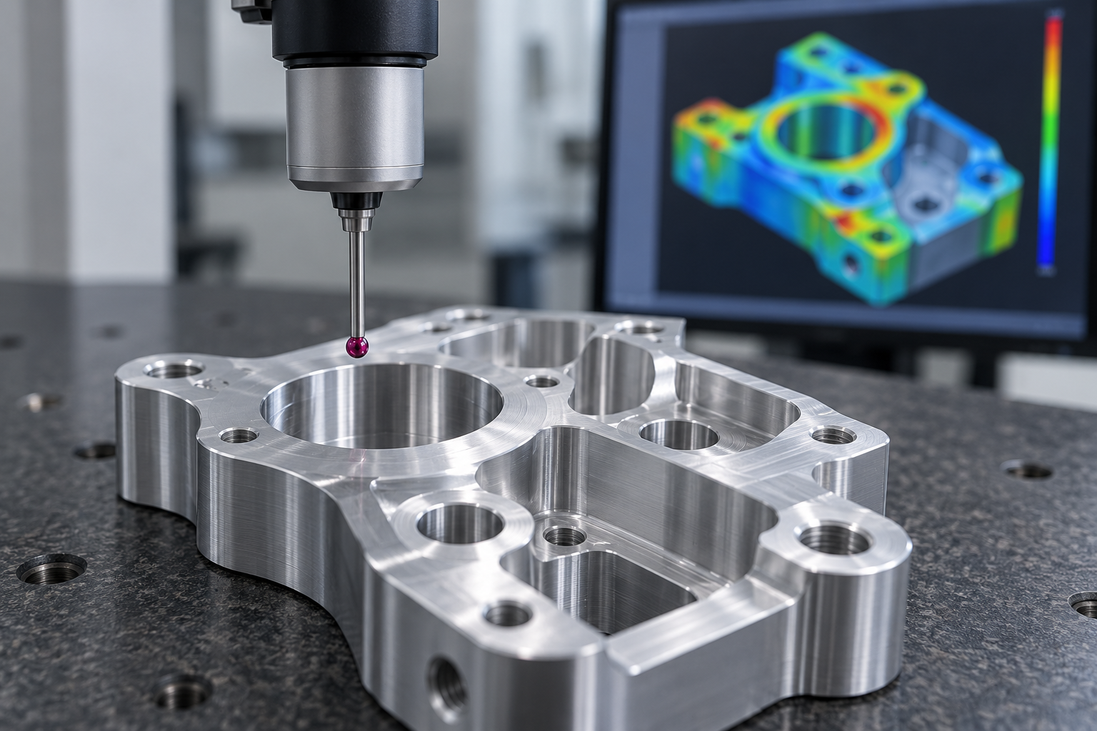
If data doesn't flow back, inspection is just after-the-fact judgment
Common questions in precision manufacturing
The following questions are the places where people most easily get stuck after reading the previous sections: how to specify tolerances for optical parts, whether to go straight to tooling for small batches, whether thin-wall parts' tolerances can be copied directly from the drawing, and why quotations always require inspection information. The answers are given according to process logic, with no commitment on lead time or precision; the specifics are subject to the drawing and prototype confirmation.
Can an ultra-precision optical component be quoted with only one dimensional tolerance?
Basically no. Dimensional tolerance governs contour position, but it cannot govern the three quantities of surface form error, surface roughness, and subsurface damage, and these are each independent and also constrain one another—turning can make the contour accurate, but surface form and roughness often need to be supplemented by subsequent grinding or polishing. When quoting, at minimum the following must be given at the same time: material (optical glass or crystal), aperture and curvature, surface form specification, roughness requirement, whether subsequent polishing is allowed, and whether acceptance is by interferometer or white light interferometry. If only one dimensional tolerance is given, the supplier can only estimate by the most conservative route, and the cost will be inflated.
Can small-batch parts skip CNC and go directly to injection molding tooling?
It depends on annual usage and how finalized the structure is. For tens to hundreds of pieces, appearance parts, or validation parts, the common industry practice is to first use CNC or hand-made duplicate molds to expose structural and assembly problems before opening the mold; the mold cost must be amortized over subsequent volume, and if the volume is insufficient it cannot be spread evenly. In addition, injection molding has constraints such as draft, wall thickness uniformity, and sink marks. If the mold is opened before the structure is finalized, the cost of mold modification is usually higher than making a duplicate mold first. It is recommended to first calculate annual usage and cycle time, then decide the route.
Can the tolerances of thin-wall parts be given directly from the drawing?
Feasibility must be judged first before setting tolerances. Thin walls will deflect under cutting forces and will chatter, and clamping itself will also compress and deform them. If the tolerances marked on the drawing do not take into account the clamping surface and process bosses, there will be no datum to rely on during machining. The common industry practice is: first confirm wall thickness and material, whether process bosses or temporary supports are allowed to be added, and set tolerances separately for key mating surfaces and non-key surfaces. For the same part, tightening from general grade to precision grade may change the cost by multiples, so tolerances should be tied to function rather than applied uniformly across the whole drawing.
Why do quotations always ask about inspection method and acceptance criteria?
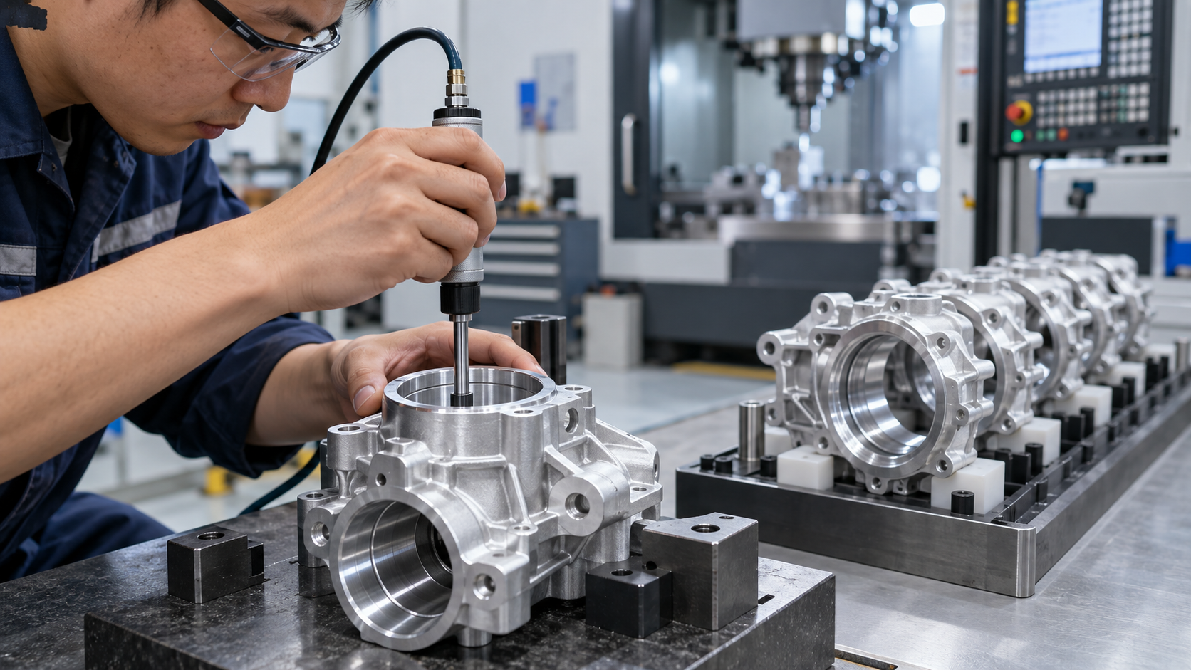
Because the inspection plan in turn determines the machining datum and fixturing scheme. Whether using a CMM, dedicated gauges, or 3D scanning for first article comparison, the measured points and datums are different, and tool compensation and process arrangement change accordingly. Many complaints of "unstable precision" are rooted in a mismatch between the inspection datum and the machining datum, not in the machine tool being inadequate. If the inspection method, sampling frequency, and acceptance criteria are made clear at the quotation stage, there will be far fewer disputes later.
What do these hot trends mean for procurement decisions?
Mainly three things: first, precision specifications are moving upward, so before quoting, key features and non-key surfaces should be separated, and the whole drawing should not be quoted at the highest precision; second, after downstream volume ramps up, consistency is harder than single-part precision, so you should ask suppliers how they manage tool life and how they conduct in-process sampling inspection; third, structures are becoming more and more extreme, and parts such as micro-holes, thin walls, and deep cavities require a feasibility judgment first. The trends themselves do not directly change unit price; what they change is which questions you should ask and what information you should add to the drawing.
Key takeaways
- Behind the hot topics is the same thing: downstream requirements for efficiency and precision are rising at the same time, transmitting pressure to process selection and inspection.
- The difficulty of ultra-precision optical elements is not just the tolerance number, but the combined control of surface roughness, figure, and subsurface damage.
- The core contradiction in the ramp-up of new energy vehicle parts is takt time and consistency; single-piece precision meeting spec does not equal batch stability.
- The more extreme the structure (micro-holes, thin walls, deep cavities), the more you must first judge accessibility before discussing tolerances; otherwise both quoting and process will be redone.
- Before quoting, clarifying the tolerance band, datum, fixturing surface, deburring, and inspection method reduces cost more than repeatedly pushing for a lower price.