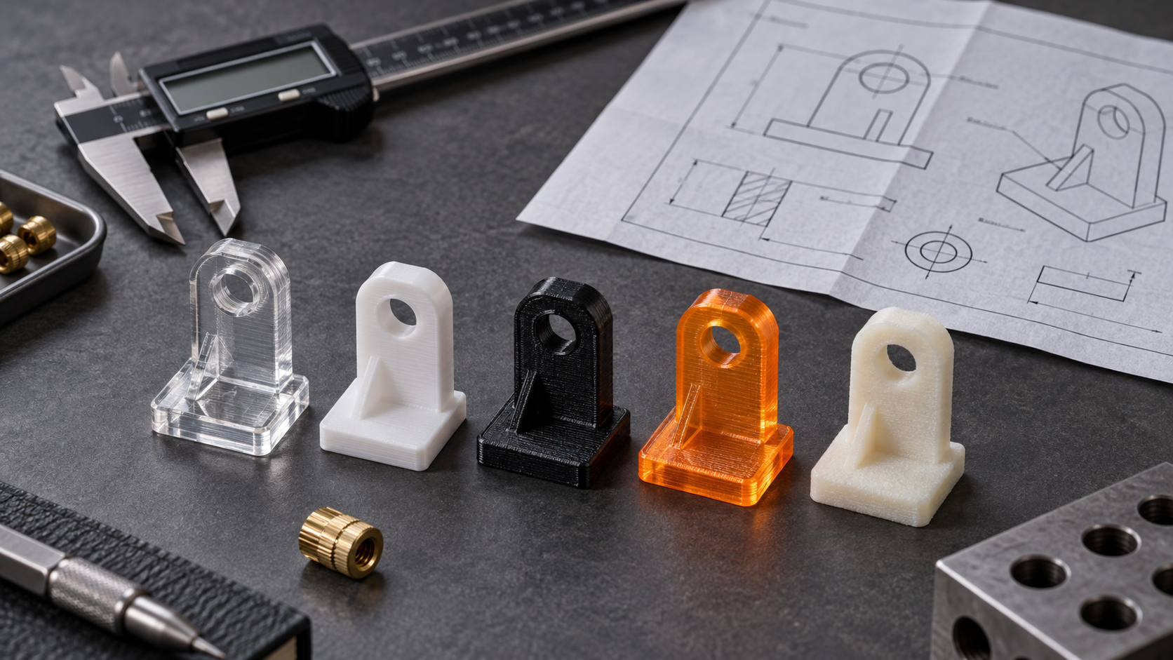
The material field on a drawing determines all the trouble that follows
Last week, while reviewing a drawing for an appearance verification part, the material field said '3D printed part, white.' The part was a top and bottom shell with snap fits, and it had to be repeatedly disassembled and reassembled during assembly. The prototype was installed the same day it came back, and the next day the root of the snap fit cracked—it used a resin-like material with insufficient toughness, and the root of the snap fit had no fillet transition. This is not a case of the material being bad; it is a case of the material field not specifying the functional grade.
Similar scenarios occur repeatedly: resin parts left in a car through a summer of sun shrink and warp; nylon parts measure as qualified when taken off the machine, but after two days the critical mating dimensions are out of tolerance—moisture absorption expansion; PLA parts used as structural parts have their hole walls simply break apart when screws are installed. None of these can be summed up with the single phrase 'the wrong material was chosen'; rather, the four things—functional grade, operating environment, assembly method, and inspection conditions—were not aligned at the drawing stage.
Material selection is not a matter of checking a 'strength ranking.' PLA's tensile strength number is higher than ABS's, but no one uses PLA for automotive interior parts. What really needs to be answered is: is this part meant to be looked at, trial-fitted, load-bearing, or used as an end-use part? At what temperature does it operate, is there UV exposure, will screws be tightened, and in what state will dimensions be accepted during measurement? Once these answers are settled, the material name naturally narrows to one or two options. Conversely, if you choose the material name first and then fill in the use case, there is a very high chance of rework in assembly or inspection.
The following unfolds in this order: first classify functional grades, then look at the real differences among the five materials, then give criteria for material selection by operating conditions, and finally land on drawing annotations, inspection, and procurement. Each section points to a judgment you can use tomorrow, rather than restating encyclopedia entries about materials.
Classify functional grades first, then discuss material names
Arguments over material selection mostly happen because both sides are talking about different things. The structural engineer asks, 'Should we use nylon or PETG?' The supplier replies, 'Either can be printed,' and in the end the first article does not fit. The problem is not the material; it is that no one first clarified which functional grade this part belongs to. Once the functional grade is set, the material name becomes meaningful; conversely, choosing the material first is equivalent to burying all the later pitfalls in assembly, inspection, and cost at once.
Divide into four grades according to actual use scenarios: appearance/concept parts only verify shape and proportions, with no load-bearing and no assembly; functional verification parts must be assembled once and moved to verify whether the mechanism interferes; assembly/load-bearing parts must be repeatedly disassembled and reassembled and withstand screw preload or snap-fit elasticity; small-batch end-use parts ship directly to users and must pass environmental, life, and acceptance requirements. When the grade jumps by one level, the material, process, and inspection method often all need to change.
| Functional Grade | Common Optional Materials/Processes | Typical Risks | Annotations That Must Be Added to the Drawing |
|---|---|---|---|
| Appearance/Concept Parts | PLA (FDM), photopolymer resin (SLA/DLP) | Resin parts are brittle and sensitive to sunlight; PLA has obvious layer lines | Appearance surface orientation, layer thickness, whether support marks are allowed |
| Functional Verification Parts | PETG, ABS, tough resin | ABS warping, dimensional drift; resin part threads break easily | Critical mating dimensions, tolerance zones, assembly direction |
| Assembly/Load-Bearing Parts | Nylon (PA/PA-CF), ABS, PETG | Dimensional change after moisture absorption; insufficient interlayer strength | Load-bearing direction, infill rate, thread/insert method |
| Small-Batch End-Use Parts | Nylon, ABS, resin (small parts), or switch to CNC/injection molding | Batch consistency, insufficient heat and weather resistance | Ambient temperature, acceptance conditions, material state |
This table is the skeleton for all subsequent judgments. Using PLA for appearance parts is fine, but do not use it to install snap fits; PETG is usually sufficient for functional verification parts, but near automotive heat sources it must be reevaluated; for load-bearing parts, prioritize nylon, at the cost of moisture absorption and directionality; for end-use parts, if volume increases, staying in 3D printing may no longer be reasonable, and injection molding or CNC should be evaluated.
The real differences among five materials: not a strength ranking
The most common mistake in material selection is treating materials as a straight line from weak to strong. PLA is cheap and easy to print, but that does not mean it can only make decorative pieces; nylon has good toughness, but that does not mean all nylon parts can take snap fits. What really determines success or failure is heat resistance, moisture absorption, anisotropy, and post-processing window, and these perform very differently across the five materials.
| PLA | Starts to soften at about 50–60°C | Brittle, notch-sensitive | Low moisture absorption, relatively stable dimensions | Fine layer lines, can be sanded and painted, poor weather resistance | Use it for automotive interior parts, load-bearing snap fits, or long-term stressed parts |
| ABS | About 80–100°C | Moderate, tougher than PLA | Moderate moisture absorption, obvious warping tendency | Can be acetone vapor polished, surface can be made fine | Large flat parts without warpage control, or ignoring volatiles from enclosed chambers |
| PETG | About 65–75°C | Good toughness, strong interlayer bonding | Moderate moisture absorption, needs drying | Slightly transparent, surface tends to be glossy, can be tapped | Use it as a high-temperature part, or for high-precision mating surfaces |
| Nylon (PA) | About 100–150°C (depending on grade) | Best toughness, fatigue resistant | Noticeable moisture absorption, dimensions swell in wet state | Surface tends to be matte, can be post-processed by machining | Assemble right after measuring, ignoring moisture conditioning, causing assembly out-of-tolerance |
| Photopolymer resin | About 60–80°C (depending on resin) | Highly brittle, poor impact resistance | Low moisture absorption, but ages over time | Finest surface, can be made transparent/rubber-like | Directly drive self-tapping screws, subject to impact, long-term outdoor use |
This table is not for looking things up; it is for ruling things out. First look at the hardest constraint in the service conditions—whether it is temperature, impact, or dimensions—then filter materials in reverse. For example, for a bracket mounted next to a motor, temperature first rules out PLA and most resins; for a snap fit that must be repeatedly disassembled, brittleness first rules out PLA and resin; for a nylon part that needs fit testing, moisture absorption first requires conditioning before measurement.
Moisture absorption: the most hidden failure source in nylon and PETG
Nylon swells in dimensions after absorbing moisture, and how much it swells depends on the grade, ambient humidity, and storage time. A common practice is to dry after printing, then place it under controlled humidity for a period to equilibrate, and only then measure and assemble. If this step is skipped, the first article may pass inspection, but after two days it will not fit. This kind of dispute between purchasing and assembly is very common. PETG absorbs moisture less noticeably than nylon, but damp material will produce bubbles and reduced interlayer strength when printed, so a dry hopper is a basic requirement.
Anisotropy: Z-direction strength is always lower than XY-direction
The interlayer bonding strength of FDM-type processes is usually only a fraction of that in the XY direction, and the specific ratio varies with material and parameters. This means that for the same material, different print orientations can lead to more than double the difference in load performance. If the drawing only specifies the material and not the load direction, the print shop will orient it to save supports and time, and the part may crack between layers during assembly, making responsibility hard to define. Load-bearing parts must have the primary load direction marked on the drawing or process card, and if necessary, switch to resin or nylon with post-processing for reinforcement.
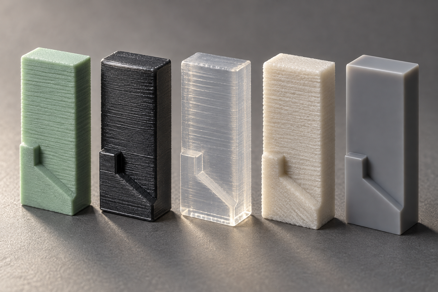
Select by operating conditions: four criteria—temperature, load, assembly, outdoor use
The material grade is only the starting point; the operating conditions are the criteria. For the same drawing, the material selection conclusion may be completely opposite when it is installed inside a car head unit versus in an outdoor cabinet. The four criteria below are ranked by priority: first temperature, then load, then assembly method, and finally environmental aging. Each criterion gives an if-then conclusion and the corresponding failure mode.
Temperature: near a heat source or exposed to sun inside a car, first rule out PLA and ordinary resins
PLA has a low glass transition temperature, with commonly cited industry reference values around 55–60 °C; in summer, the surface temperature of a car dashboard can easily exceed 70 °C, and PLA parts will soften and warp, causing clips to lose clamping force. The heat resistance range of ordinary photosensitive resins is also narrow, depending on the resin system; if the drawing does not specify it, do not assume it can withstand above 60 °C for the long term. If the part is near a motor, power supply, or an area exposed to sun inside a car, prioritize ABS, PETG, or nylon; when there is a clear numerical heat resistance requirement, ask the supplier to provide the measured heat deflection temperature of that batch of material rather than just looking at the grade name.
Load: for parts subject to bending and impact, do not gamble on brittle materials
PLA has decent rigidity but is brittle, undergoing brittle fracture under impact, with a flat fracture surface and almost no yield stage. ABS and PETG are noticeably tougher, and PETG usually has better interlayer bonding than ABS, making it suitable for clips, fixtures, and brackets subject to bending. Nylon (PA) ranks near the top among the five materials in toughness and fatigue resistance, but its dimensions change after moisture absorption, so load-bearing parts must include the conditioning state in the acceptance conditions. Decision rule: if the part will be repeatedly bent during assembly or use, or subjected to drop impact, rule out PLA and ordinary resins; if it is only under static compression, PLA can still be used in a dry environment at room temperature, but you must accept the fact that it is brittle.
Assembly: if screws will be tapped, nuts pressed in, or clips made, first look at creep and thread strength
When PLA and resin parts are directly tapped for screws, the threads will strip after a few disassemblies; resin parts are more brittle, and self-tapping screws easily cause cracks in the hole wall. For connections that need repeated disassembly, a common approach is to reserve mounting holes for heat-set brass nuts or embedded inserts, or switch to PETG, ABS, or nylon. Nylon clips have good elastic recovery, but under long-term load they will creep, and clamping force decreases over time; if the clip needs to maintain clamping force for a long time, design in compensation or switch to a metal spring. ABS can be solvent polished or vapor treated to improve the surface, but this slightly affects dimensions, so mating surfaces need allowance.
Outdoor and humid: UV and moisture absorption are two independent failure paths
Outdoor parts must consider both UV aging and moisture absorption. ABS has average weather resistance and will chalk and discolor after long-term sun exposure; PETG has slightly better weather resistance, but it is still not a long-term outdoor material. Nylon expands in dimensions after moisture absorption, with commonly cited industry reference values on the order of 0.5%–2%, depending on the grade and conditioning state, and thin-walled parts and long parts are affected more noticeably. If a part is both outdoors and requires dimensional stability, it is usually necessary to switch to a weather-resistant grade or consider CNC-machined metal parts. Decision rule: long-term outdoor use + dimensional sensitivity—do not look for the answer only among 3D printing materials; evaluate CNC or sheet metal options.
| Operating condition criterion | Preferred choice | Avoid | Typical failure mode |
|---|---|---|---|
| Near a heat source / exposed to sun inside a car (>60 °C) | ABS, PETG, nylon; heat-resistant resins require measured confirmation | PLA, ordinary photosensitive resins | Softening and warping, clips losing clamping force |
| Repeated bending / drop impact | PETG, ABS, nylon | PLA, ordinary resins | Brittle fracture, interlayer cracking |
| Repeated disassembly / pressed nuts / clips | PETG, ABS, nylon + inserts | Directly tapped PLA, self-tapping resin | Thread stripping, cracks in hole walls, creep relaxation |
| Outdoor / humid + dimensionally sensitive | Weather-resistant grade; evaluate CNC / sheet metal | ABS under long-term sun exposure, nylon without conditioning | UV chalking, out-of-tolerance swelling from moisture absorption |
These four criteria do not replace one another. If an in-car clip part simultaneously hits temperature, load, and assembly, the most severe one should be taken as the baseline during material selection rather than compromising. When unsure, write the operating conditions as one sentence and send it with the drawing to engineering; that is faster than guessing in a material table. When materials and processes need to be checked against operating conditions, you can submit the drawing through the 3D printing quote entry and let engineering give recommendations based on the service conditions.
Annotations that must be added to the drawing: material, orientation, infill, post-processing
The most common rework is not the printer going off track, but insufficient drawing information, leaving the shop to guess based on default parameters. Writing “3D printing” or “nylon” in the material field is almost the same as writing nothing. Below is a list of annotations that can be copied directly into a drawing or RFQ.
Material field: write the grade and state, not the broad category
Writing “PA12” is more useful than writing “nylon,” and writing “PA12 after conditioning” is more useful than writing “PA12.” SLS nylon parts have low moisture content when they come off the machine, and moisture absorption after a few days will cause swelling, so assembly holes may change from an interference fit to a clearance fit. The drawing should at least specify: material grade, process (FDM/SLA/SLS/MJF/DMLS), whether conditioned, and whether annealed. FDM ABS and injection-molded ABS are not the same state; the former’s interlayer strength is greatly affected by nozzle temperature and chamber temperature, so the annotation should preferably state “accepted according to the FDM process” to avoid using injection molding data to judge printed parts.
Orientation, infill, and critical dimensions: view all three together
The Z-direction tensile strength of FDM parts is typically only about half that of the XY direction, with a common industry gap of 40%–60%, varying with material and parameters. The load direction must be marked on the drawing, or simply state "the interlayer direction must not be perpendicular to the primary load direction." Infill rate and wall thickness determine stiffness; a part with 15% infill is fine for appearance, but a load-bearing snap-fit will break at the layer lines first. Critical mating dimensions should be listed separately with tolerance bands noted, not just an overall "±0.2 mm," because shrinkage differs by direction, and the actual deviation on the long side versus the short side can differ by a factor of two.
Support surfaces, threads, and inserts: high-risk areas for assembly failure
After support is removed, the surface is rough. If that surface is a sealing surface or a sliding fit surface, you must note "non-support surface" or specify sanding. Threads formed directly by 3D printing have low strength, and sizes below M3 are especially prone to stripping. The drawing should state "reserve a tapped pilot hole at the thread" or "heat-set brass nut," and give the insert model and press-in depth. Without this, the first article will most likely be scrapped at the assembly station.
| Material grade | Use the cheapest or in-stock material | Temperature resistance and toughness fail to meet requirements, functional testing fails |
| Print orientation | Oriented to save time in nesting | Load direction falls on the interlayer, breaks on impact |
| Infill rate/wall thickness | 15% infill, 2 walls | Insufficient stiffness, deformation during assembly |
| Critical dimension tolerances | Overall conventional precision | Mating surfaces out of tolerance, requires CNC rework |
| Post-processing and conditioning | Shipped directly without treatment | Nylon parts drift in dimensions after moisture absorption |
Only after the above items are completed do the "material cost" and "post-processing cost" on the quote have a basis, and only then does the first article have a reproducible acceptance baseline. If the drawing currently only has the outer shape, it is recommended to also explain the functional grade and operating environment when requesting a quote, so the process side can first suggest material and orientation, then feed that back into the drawing. When you need a quick price comparison, you can use the 3D printing quote portal to upload the model and attach the above annotations, reducing back-and-forth confirmation.
Inspection and procurement: when the material changes, the gauges and acceptance method must change too
On the same drawing, if the material field changes from ABS to nylon, the dimensions do not move, but the inspection results may be completely different. Acceptance of 3D printed parts cannot copy the logic of injection molding or machining—the material itself absorbs moisture, shrinks by direction, and continues to deform during post-processing. The inspection plan must follow the material, and procurement inquiries must also clearly state the "material state," otherwise it is normal for the first article to pass and the batch to become a dispute.
How to define critical dimensions: first separate "shape dimensions" and "mating dimensions"
What truly needs calipers/CMM on a 3D printed part are mating dimensions and assembly datums, not the outer contour. Outer dimensions are strongly affected by print orientation, shrinkage, and support removal, so free tolerances are usually sufficient; mating holes, shafts, snap-fit spacing, and mounting surface flatness are the acceptance focus. Judgment principles:
- Hole/shaft fits: prefer plug gauges or pin gauges, do not use calipers to measure inner diameters—the inner holes of FDM and SLA are actually approximately polygonal or stepped surfaces, and caliper readings run large.
- Mounting surfaces: use a surface plate plus feeler gauge or CMM to measure flatness. Nylon and ABS parts commonly warp after cooling, and flatness is often 0.2–0.5 mm worse than the marked tolerance. This is common in the industry and must be confirmed against the drawing.
- Snap-fits/elastic arms: measure spacing and wall thickness, not single-point dimensions. A 0.1 mm thickness deviation on an elastic arm can double the insertion/removal force.
- Threads and inserts: printed threads are not recommended as an acceptance dimension; accept by pilot hole + self-tapping or heat-set insert, and define insert pull-out force separately.
Which dimensions are most affected by moisture absorption and orientation
Nylon (PA) expands in dimensions after absorbing moisture; this is a material characteristic, not a printing defect. When PA12 is placed in a humid environment for several days, linear dimensions may change by 0.2%–0.5%, which on large parts is several tenths of a millimeter. The effect of orientation is equally obvious: FDM parts are weaker in both strength and dimensional stability in the interlayer (Z) direction than in the XY direction. If a mating surface falls in the Z direction, the assembly clearance must be made larger than in the XY direction. Resin parts are the opposite: SLA has good dimensional stability, but slowly creeps under long-term exposure to UV and moisture, so precision mating surfaces should not rely on it long term.
Four things to state clearly in a procurement inquiry
"Same material, different state" is the most common source of disputes in 3D printing procurement. At inquiry, at least state clearly:
- Material grade and state: write PA12 or PA12+glass fiber, write "delivered in dry state" or "delivered in conditioned state." If not written, the supplier defaults to delivering in the natural state after printing.
- Acceptance dimensions and gauges: list which dimensions are critical and what gauges are used to measure them. Writing only "per drawing" is usually not enough; 3D printed parts need clarity on which dimensions are exempt from inspection.
- Post-processing requirements: support removal, sanding, sandblasting, dyeing, annealing, conditioning—each affects dimensions and appearance. If not written, it will be done in the least effortful way.
- Inspection report requirements: whether a first article report, actual measured values of critical dimensions, and material batch are needed. Recommended for small-batch end-use parts; can be omitted for appearance validation parts.
If the material field on the drawing only says "nylon" or "resin," the quote and first article will most likely go off track. Adding the material state and acceptance conditions to the drawing or inquiry form is far cheaper than rework afterward. When you need a quick price check, you can upload the drawing and note the material state at the 3D printing quote portal, or confirm the available materials and post-processing scope on the 3D printing capabilities page.
When this material selection logic does not apply
The criteria in the previous sections are all built on the premise that "the part uses general-purpose engineering plastics, the service temperature does not exceed 80 ℃, and the batch size is in the tens to hundreds." Once you cross the following three lines, continuing to choose among PLA, ABS, PETG, nylon, and resin will only drag the problem out.
Long-term high temperature, flame retardant, medical, food contact
In situations involving long-term exposure above 100 ℃, or requiring UL flame retardant rating, biocompatibility, or food contact compliance, general-purpose material systems are basically not applicable. Such requirements correspond to high-temperature engineering plastics such as PEEK, PEI, and PPS, or resin systems with specialized certifications, and often require supporting post-processing such as annealing and hot isostatic pressing. These materials have narrow printing windows, high difficulty in controlling shrinkage and warping, and their quotes and lead times will also jump significantly. When encountering such drawings, the correct action is to first write the operating conditions (temperature, medium, certification requirements) clearly, then confirm whether the equipment and materials match, rather than first choosing a "close enough" general-purpose material for prototyping.
High-precision mating surfaces: usually still require CNC after printing
Dimensions that need to mate with bearings, pins, and sealing surfaces often have tolerance bands within ±0.02 mm, and geometric tolerances must also be controlled. Direct printing with FDM and SLA struggles to reliably achieve this level; even if a single piece measures as qualified, batch consistency cannot hold up. The common industry practice is to print a blank with allowance, then use CNC to finish the mating surfaces. The rule of judgment is simple: for any dimension requiring press fitting, sliding fit, or sealing, do not expect printing to achieve it directly; reserve a post-machining step in the process route.
Large-volume end-use parts: time to evaluate injection molding
When a part is to be mass-produced in thousands of units or more, the per-unit printing cost almost never decreases with quantity, while the mold cost of injection molding gets amortized. Continuing to use 3D printing at this point usually just postpones the mold-opening decision. The reasonable path is: use printed parts to complete functional verification and assembly confirmation, freeze the structure, then switch to injection molding. Note that before switching to injection molding, checks such as draft, wall thickness uniformity, and gate location must be added; structures that work on printed parts may not be moldable in injection molding. This type of transition can go through a joint evaluation of injection molding capabilities and rapid prototyping.
Common questions
The following are the ones most often pressed on during quoting and first-article review. The answers all come with conditions—whether a material can be used depends on the operating conditions and acceptance method, not on whether the material's name sounds good.
Can PLA parts be used as functional parts?
It depends on the functional level. For low-load, room-temperature, impact-free situations such as appearance verification, assembly interference checks, and fixture locating blocks, PLA is sufficient, and it prints stably with a good surface. But when it involves continuous load, repeated disassembly and assembly of snap fits, proximity to heat sources, or sun exposure inside a car, PLA's heat resistance and creep are hard weaknesses; it will slowly deform under long-term load and is somewhat brittle under impact. For such parts, it is recommended to switch to PETG, ABS, or nylon, and not to gamble on functional parts using the cost logic of appearance parts.
Can resin parts (SLA/DLP) be directly tapped with self-tapping screws or threaded?
Direct tapping under load is not recommended. Most photosensitive resins have limited toughness, and self-tapping screws easily crack at the thread root when tightened, especially with repeated disassembly and assembly. The common practice is to leave insert holes and secure metal inserts with heat-set brass nuts or structural adhesive, delegating the load to the metal. If threads must be made directly, they can only be used in low-torque, low-disassembly situations, and the thread specification and allowable torque should be noted on the drawing, with destructive verification on the first article.
Why do nylon parts measure out of tolerance?
First rule out moisture absorption. Nylon (especially PA6/PA12) absorbs moisture from the environment and expands accordingly; measuring right off the machine versus after a few days can differ by a considerable amount, and thin-walled parts are more obvious. Next is printing orientation and anisotropy; the same dimension behaves differently along the interlayer and intralayer directions. The order of judgment: confirm whether it has been conditioned to a stable state, confirm that the measurement direction matches the modeling direction, and confirm whether critical dimensions fall in the moisture-sensitive zone. If the assembly fit is tight, it is better to leave clearance based on the conditioned state than to set tolerances based on dimensions right off the machine.
How to choose between PETG and ABS?
Decide based on the environment and post-processing needs. If you need weather resistance, food-contact or medical scenarios (corresponding compliant grades required), low odor, and easy printing, lean toward PETG; if you need higher heat resistance, acetone polishing or subsequent bonding, and a toughness feel close to injection-molded parts, lean toward ABS (note warping and odor, requiring an enclosed chamber). Neither is a material for long-term high-temperature load, and near heat sources you still need to choose another material. If it is only an appearance part, PETG is usually less troublesome.
How should the material column on a drawing be written so it will not be made wrong?
Do not just write "3D printing" or "plastic." At minimum, write clearly: material system and grade (such as PA12, PETG), process (FDM/SLS/SLA, etc.), critical dimensions and tolerance bands, load direction and printing direction requirements, infill rate and layer thickness, post-processing (support removal, conditioning, polishing, painting), and acceptance method. If any item is missing, the quote and first article may proceed with default values, and in the end the dispute will be about "the same material in different states." For items you are unsure about, ask engineering directly during quoting; do not leave them blank.
Key takeaways
- Define the functional grade first, then choose the material: for appearance verification only, PLA/resin can be prioritized; for snap fits, threads, and bending parts, go directly to PETG, ABS, or nylon, and do not repeatedly redesign the structure in PLA.
- Select heat resistance based on the 'maximum operating environment temperature + safety margin,' not on a single data sheet value; near heat sources or in automotive interior conditions, PLA usually fails first.
- Manage resin parts as 'brittle + UV-sensitive + moisture-sensitive': do not default to standard resin for load-bearing, snap-fit, or threaded connections; switch to engineering resin and perform drop/tightening verification.
- Nylon part drawings must specify moisture absorption and orientation: dimensions change before and after conditioning, Z-direction strength is usually lower than XY-direction, and the critical load-bearing direction must be clearly stated.
- When writing the material into the drawing, also clearly specify the process, infill/wall thickness, support surfaces, post-processing, and critical dimension inspection method; otherwise quotes and first articles will each be made according to their own interpretation.



