Don't rush to check the material table yet: which questions must be answered first when choosing materials for a part?
Many people receive a drawing and immediately open a materials handbook, picking one from grades like 6061, 304, or POM that "looks right." This order is actually reversed. Choosing materials for a part is not about choosing the name with the best-looking material properties, but about answering a set of constraint questions: how will it fail, how much failure is allowed, in what environment will it fail, and how many parts will be made. Once these four questions are answered clearly, the material table shrinks from hundreds of rows to a shortlist of three to five candidates.
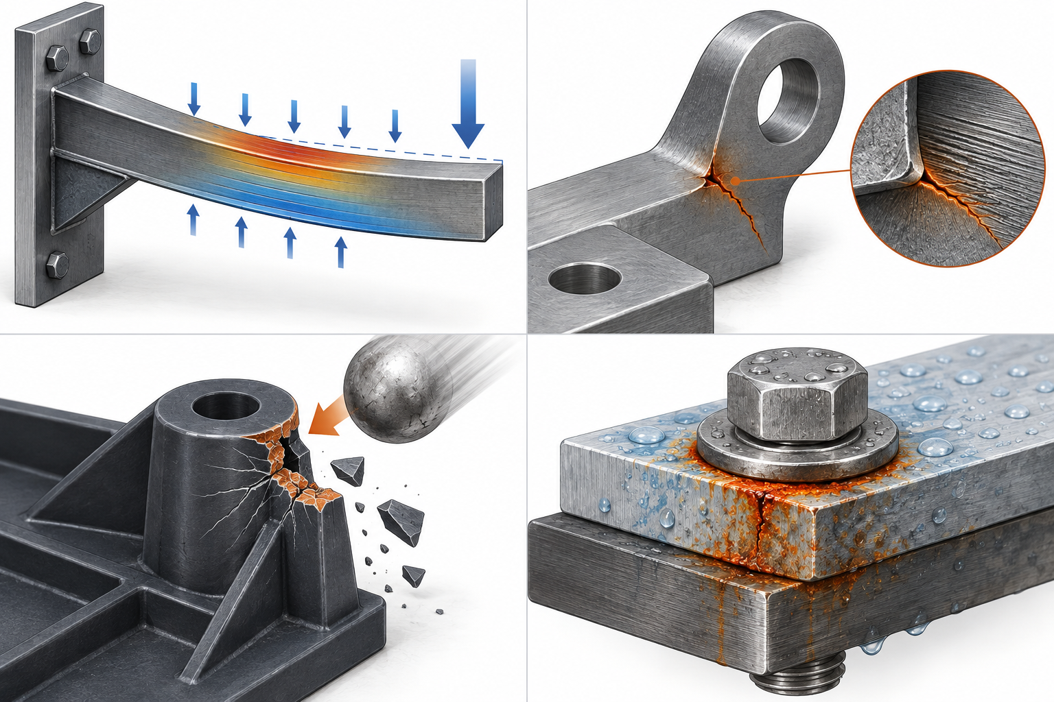
More specifically, the first step is to ask about load. Is the part subjected to static tension, repeated bending, impact, or long-term sliding friction? With different load types, the same material may perform in completely opposite ways. For example, an aluminum alloy may have sufficient static strength, but under alternating loads it may crack prematurely because of notch sensitivity.
The second step is to ask about deformation. The allowable elastic deformation, long-term creep, and dimensional drift caused by thermal expansion will directly eliminate a group of materials. The material selection logic for a bracket that requires stable positioning accuracy is completely different from that for a housing that only needs to fit together.
The third step is to ask about environment. Temperature range, humidity, medium, UV, and contact with dissimilar metals are hidden drivers of material failure. Many field problems are not due to insufficient strength, but to galvanic corrosion, plastic water absorption and swelling, or low-temperature embrittlement. If this step is skipped, even detailed calculations later may be wasted.
The fourth step is to ask about batch size. Making one piece, fifty pieces, or fifty thousand pieces are completely different worlds of material selection. For a single part, high processing costs can be tolerated for performance; for large batches, the process must be accommodated in reverse, and the material must adapt to the mold, draft, and shrinkage. Batch size determines whether you can consider routes such as injection molding or die casting that require tooling.
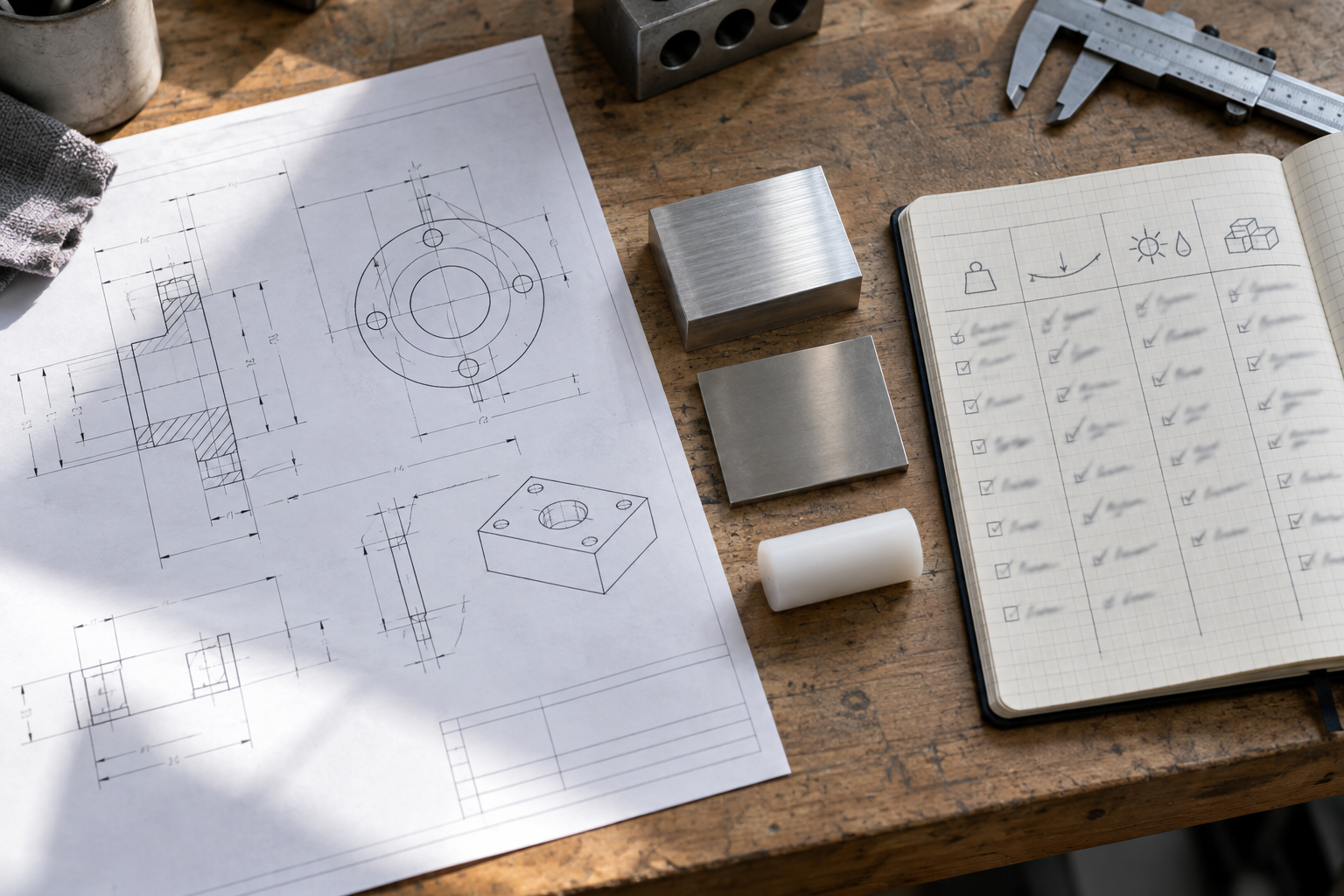
Once these four questions are answered, the screening order in this article is set: failure mode → performance threshold → geometry and tolerance → process and batch size → cost and verification. It is a funnel, and each layer subtracts. First think clearly about how the part will fail, then define what metrics the material must meet; next see whether structural features will directly eliminate certain materials; then use batch size to frame the process range, which in turn narrows the material candidates; finally compare cost and verify with a small sample or first article.
In plain terms, choosing materials is like seeing a doctor: first look at the symptoms (failure), then decide the tests (metrics), then rule out contraindications (structure and process), and only then prescribe medicine (grade). Calling out a drug name right away often either fails to cure the problem or over-treats it—using a much more expensive material to solve a problem actually caused by structure and fixturing. On the next page, we will first break down the most critical layer: "failure mode."
Working backward from failure modes to performance thresholds: how to rank strength, toughness, hardness, and corrosion resistance
The most common mistake when selecting materials for a part is asking "is this material good?" first, then looking for reasons afterward. A more reliable approach is the reverse: first assume how it will fail, then work backward to determine which performance property needs to meet the threshold first. The same material table, placed in two scenarios—"static fracture" and "cyclic fatigue"—yields completely different rankings.
Let's start with the conclusion: performance metrics have no absolute priority, only a priority bound to the operating conditions. Discussing "is the strength high enough" without considering temperature, medium, load type, and life requirements is meaningless. Below, we break it down by common failure modes.
Static fracture depends on strength and safety factor; fatigue depends on notches and surface
For one-time tension, compression, or bending, the main considerations are yield strength and tensile strength, paired with a safety factor. A common industry practice is to apply a safety factor of 1.5 to 3 times based on operating conditions, with higher values for impact or uncertain loads; the specific multiplier must be confirmed against the drawing and actual conditions, not copied blindly.
But for parts under repeated loading, such as a connecting rod in reciprocating motion or a bracket that starts and stops frequently, what controls failure is often not strength but notch sensitivity and surface condition. Sharp corners, thread roots, and rough tool marks are all crack initiation points. In this case, increasing material strength may actually reduce toughness, which isn't necessarily worthwhile. For the same 6061-T6, after surface polishing to remove tool marks, fatigue performance is typically significantly better than the same part with machining marks.
Impact depends on toughness; wear depends on hardness and mating surfaces
For parts subjected to drops, impacts, or sudden overloads, toughness takes priority over hardness. Hard and brittle materials tend to chip at corners under impact—brittle plastics and hardened steel fall into this category and are not suitable for thin-walled guards or clips subjected to impact.
For sliding fits, frequent insertion and removal, and contact surfaces with relative motion, hardness and surface roughness are the key factors. Hardness determines resistance to abrasive wear and adhesion, but the fit involves both sides—increasing the hardness of only one part may transfer all wear to the mating part. Therefore, wear scenarios require specifying the material and surface treatment for both mating parts simultaneously, rather than selecting a single "hardest" one.
Corrosion depends on the medium and galvanic pairing, not on the word "stainless steel"
"Corrosion resistance" is relative to the medium. 304 stainless steel performs well in the atmosphere, fresh water, and most food environments, but is prone to pitting in the presence of chloride ions (coastal atmosphere, chlorine-containing disinfectants, salt water); 316 has a higher molybdenum content and generally better chloride resistance, but it is not universal. Carbon steel can sit for a long time in a dry indoor environment, but rusts when exposed to moisture.
More insidious is galvanic corrosion: when two metals with a large potential difference are in direct contact, and a small amount of electrolyte (condensation, cleaning fluid) is present, the one with the lower potential will corrode faster. Directly assembling aluminum with stainless steel, or carbon steel with copper alloys, are typical combinations. The solution is isolation—adding insulating gaskets, coatings, or switching to materials with similar potentials. This point is often overlooked on assembly drawings, yet it repeatedly occurs in outdoor and humid environments.
Ranking these categories reveals that the order of material selection is actually: first identify the dominant failure mode, then select the corresponding primary control metric, with the remaining metrics as constraints. For example, for an outdoor bracket, the dominant factors are corrosion and fatigue, and strength only needs to be sufficient; for a drop-hammer impact guard, the dominant factor is toughness, and hardness should actually be kept low.
Geometry, tolerances, and surface roughness: which structural features will directly disqualify a material
The first two steps screen for "can it hold up." The next step is more practical: what the part looks like often has more veto power over material selection than how much force it bears. The same block of 6061 aluminum is fine as a 2 mm thin-walled square shell, but as a 0.8 mm slender cantilever it's just waiting for tool deflection and deformation; the same 7075 shaft is easy to turn in the solid section, but with cross-shaped deep grooves it becomes a dancing tool tip. If you don't look at geometry first when selecting materials, it's easy to write a plan that scores full marks on performance and zero on machinability.
Thin walls, deep cavities, slender rods: materials with insufficient rigidity are eliminated first
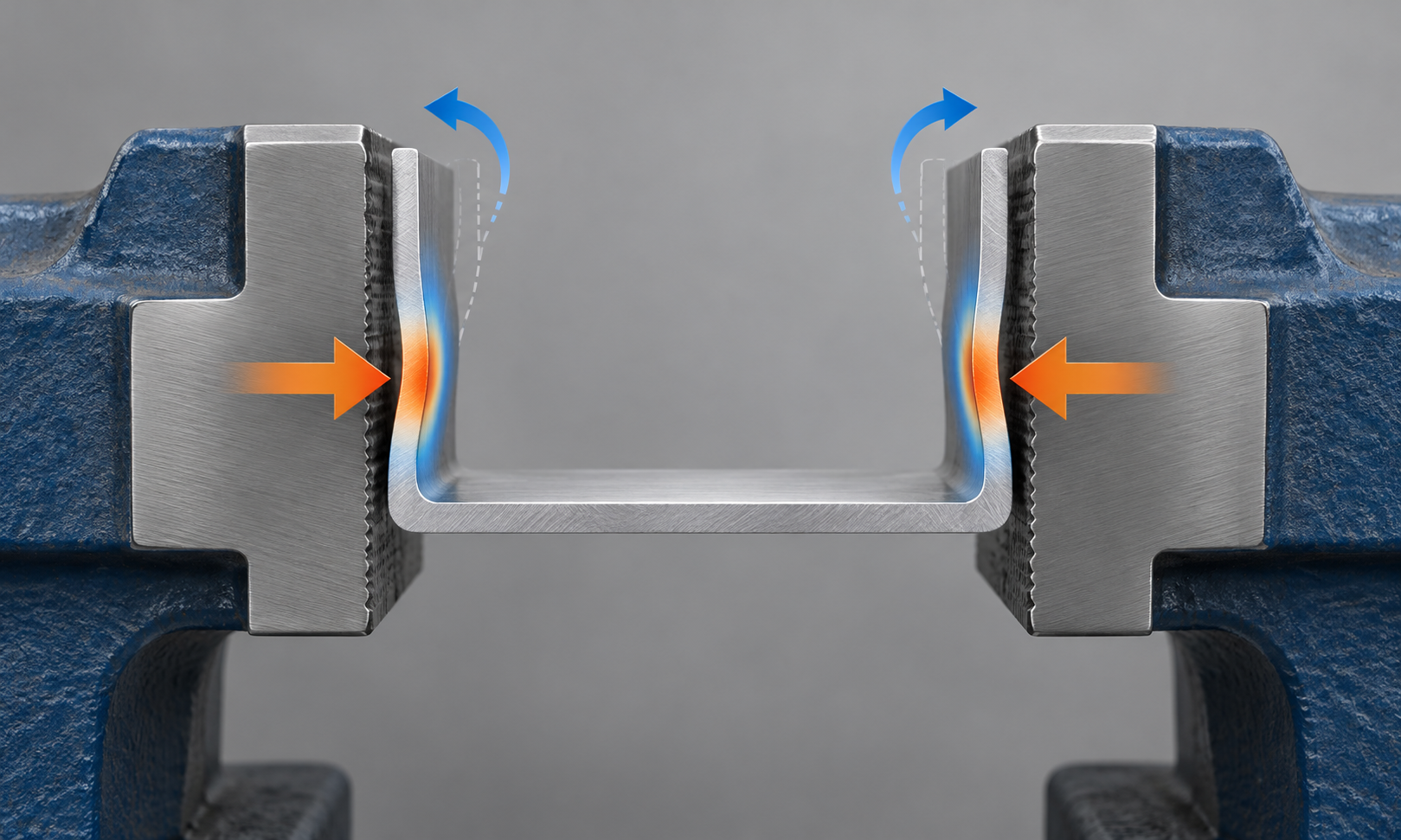
Thin-walled and slender structures fear two things most: clamping force and cutting force. The softer and less rigid the material, the more easily it gets dented or springs back during clamping, and the dimensions drift back after release; during cutting, chatter is likely, leaving ripples on the surface. A common industry rule of thumb is that for aluminum alloy thin-walled parts, wall thickness should not easily go below 1 mm; steel parts can be thinner but heat treatment distortion must be considered; and plastic parts like POM and nylon, even with sufficient wall thickness, tend to change dimensions within a few days due to moisture absorption or internal stress. Deep cavities (depth exceeding 3–4 times the tool diameter) test chip evacuation and tool overhang—soft and sticky materials tend to wrap chips and burn tools, while hard and brittle materials tend to chip edges. Slender rods (length-to-diameter ratio greater than 10) almost inevitably require a steady rest or segmented machining, in which case material rigidity directly determines whether it can be completed in a single setup.
Tolerance bands and surface roughness will in turn lock down the material
Many people think tolerances are a machining issue, but in fact they constrain the material first. For an IT6-grade mating hole, the material must be capable of stable cutting and its coefficient of thermal expansion must not be too extreme; otherwise it measures as acceptable but becomes an interference fit during assembly. For a sealing surface at Ra 0.4, the material must be grindable or precision-turnable. Cast iron and free-machining steel excel at this kind of work, but switch to soft aluminum and it tends to stick to the tool and tear; switch to titanium alloy and you have to reduce speeds, change tools, and double the machining time. Conversely, if the drawing only specifies an ordinary mounting surface at Ra 3.2, there is no need to choose an expensive material for a slight gain in surface quality. So when reading a drawing, scan three things first: the tightest tolerance band, the finest surface roughness, and the thinnest or deepest feature—these three basically determine the upper limit of the material candidate list.
There is a chain reaction here that is easily overlooked: to achieve a certain surface roughness, the process may switch from milling to grinding or lapping, and lapping has a lower limit requirement on material hardness—too soft a material will "clog the grinding wheel." Similarly, to hold a certain tolerance, an aging treatment or annealing step may need to be added, and some plastics and aluminum alloys are temperature-sensitive, so their dimensions may actually drift further after heat treatment. The conclusion is: tolerances and roughness are not numbers written separately on a drawing; together with material and process, they form a set of parameters that must be determined simultaneously. In Agile-X / AGX's CNC machining capabilities, this kind of "geometry—material—process" linked judgment is usually reviewed together with the drawing before quoting.
Brittle materials vs. impact, threads vs. sharp corners: another way to be eliminated
There is another category of elimination that has nothing to do with rigidity, but with "whether the feature can be made safely." Cast iron, ceramics, and some high-silicon aluminum alloys are highly brittle and are not suitable for impact-bearing snap fits or thin-wall cantilevers; the exit edge tends to chip during drilling. For small threads below M2, too soft a material will strip the threads, while too hard a material will break the tap; a medium-hardness, tough material is actually the most reliable. Sharp internal corners (R smaller than the tool radius) cannot be produced by milling, and if the material is both hard and gummy, the cost of EDM or wire cutting immediately goes up. If a part has sharp corners, deep narrow slots, and sealing surfaces all at once, don't rush to pick a grade—first ask: can these features be changed? If they can't, the material selection range is actually already very narrow.
Batch size and process: the material ranges available for CNC, 3D printing, sheet metal, vacuum casting, and injection molding
After the previous layers of screening, you should have a "performance threshold checklist" in hand—strength, toughness, corrosion resistance, service temperature, and media to avoid. But a checklist does not turn itself into a grade. In between there is still a very hard filter: how many parts are to be made determines which processes you can use; once the process is fixed, the material candidates narrow dramatically as well. For the same drawing, making 1 part and making 50,000 parts often means the usable material families are not the same batch. The difficulty in material selection for parts is often not "which material is better," but "at this batch size, which materials simply cannot be made."
From one piece to a few dozen: the material boundaries of CNC and 3D printing
For one-offs, small batches, and prototyping, the mainstays are CNC machining and 3D printing. Their material pools do not overlap much, and the selection approaches differ. CNC is subtractive, so as long as a material "can be cut by the tool and held in the fixture," it can basically be made: aluminum alloys (6061, 7075, 2024, etc.), stainless steels (303, 304, 316, 17-4PH), brass, titanium alloys, and engineering plastics (POM, PEEK, PC, nylon, acrylic) are all within the common range. A common industry judgment is: for prototypes and small batches, prioritize free-machining grades, such as 6061-T6 or 303 stainless steel, to minimize the risks of fixturing, deformation, and tool wear; if you really need 7075 or 17-4PH, first confirm whether the supplier has the corresponding tooling and experience.
3D printing is additive, and its material range is more obviously limited by equipment and process: FDM commonly uses PLA, PETG, ABS, nylon, and PC; SLA uses photosensitive resin; SLS/MJF uses nylon powder; metal processes such as DMLS mostly use stainless steel, aluminum alloy, titanium alloy, cobalt chrome, etc. Its strengths are complex internal cavities and lightweight structures; its weaknesses are anisotropy and surface roughness—interlayer strength is usually lower than in-layer strength, and sealing surfaces and precision mating surfaces often still require post-machining. To bring the mating surface of a 3D-printed part below Ra 0.8, you need to leave machining allowance and then put it on a machine tool, which means returning to the CNC process chain.
From a few dozen to a few hundred: the applicable range of vacuum casting (duplicate molds for prototypes)
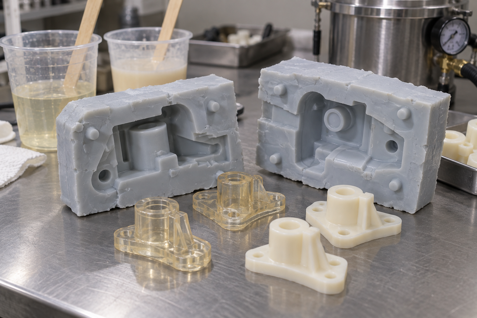
A few dozen to a few hundred pieces is an awkward range: CNC unit cost cannot come down, and injection molding tooling is not cost-effective. Vacuum casting (duplicate molds for prototypes) is often used here—first a silicone mold is made from the original master, then polyurethane-type resins are cast into it, producing small batches with an appearance close to injection molding. The materials are mainly various polyurethane resins, which can be adjusted for hardness, color, and some mechanical properties, and can also make transparent parts. The limitations are that resin temperature resistance and weather resistance are generally inferior to engineering plastics, so long-term load-bearing or high-temperature service requires caution; mold life is limited, and precision usually drifts after a few dozen to about a hundred pieces, with the specific numbers subject to the supplier's actual testing. It is a transitional solution, not an endgame solution.
Sheet metal and injection molding: sheet constraints and mold constraints
Sheet metal fabrication does not run on "grade freedom"; it runs on sheet specifications. Commonly used are cold-rolled sheet, hot-rolled sheet, galvanized sheet, stainless steel sheet, aluminum sheet, and copper sheet, and thicknesses are discrete—if you write 1.8 mm, the supplier may only have 1.5 or 2.0 mm in stock. Bend radius, minimum hole-to-edge distance, and developed dimensions are also constrained by material ductility: aluminum sheet tends to crack when bent, hard-temper stainless steel has large springback, and the thicker the material, the more pronounced it is. So material selection for sheet metal parts is essentially matching within the available sheet thickness table + bending capability, rather than casually picking a metal grade.
Injection molding follows another logic: the material can be almost anything—ABS, PC, PC/ABS, PA, POM, PMMA, PP, and TPE can all be used—but the mold ties the material down. Shrinkage determines mold dimensions; glass-fiber-reinforced materials have obvious anisotropic shrinkage and wear the mold harder; walls that are too thin make flow difficult, while walls that are too thick cause sink marks; insufficient draft angle causes scuffing during ejection. Once the mold is cut, the material basically cannot be changed—changing material means changing the mold. So when discussing injection molding at the tens-of-thousands level, material decisions must be made in sync with mold design, rather than choosing the material first and then drawing the mold. Once the process is fixed, the material candidates narrow dramatically—this statement is most fully demonstrated in injection molding.
Looking at these process categories together reveals a pattern: the larger the batch, the more material selection is constrained by the process; the smaller the batch, the freer the material choice, but the higher the unit price. In practice, the order for selecting materials for a part is usually to first narrow down 1–2 feasible processes based on batch size, then screen for performance within that process's material list—rather than starting from page one of a materials handbook. To quickly compare the materials and achievable ranges under a given process, you can first look at the corresponding capability page or material library, then confirm with your drawings in hand.
Cost is not unit price: the impact of material utilization, tool life, post-processing, and inspection
Many people compare material prices by opening a supplier quote sheet, looking at the price per kilogram, and picking the cheaper one. This approach is almost guaranteed to go wrong when selecting materials for a part, because material is only one item in the cost—and often not the largest one. What truly determines the per-piece cost is how many operations the batch must go through, how much material is scrapped, how many tools are consumed, and how many gauges are needed.
Blank specifications and material utilization: cheap material often means more waste
Start by calculating utilization. For the same part, using plate or bar stock close to the finished dimensions versus using a blank one size larger can more than double the material cost, because the cut-off portion was also paid for. What can be changed at the design stage is the blank form—switching a square part to nested cutting from plate, or a turned part to a standard bar diameter, often saves more money than changing the material grade. A common industry practice is to leave 2–5 mm allowance per side on the blank, but the specific amount depends on the fixturing method and heat treatment distortion, and must be confirmed against the drawing and process—it cannot be generalized.
Tool life and machining time: higher hardness means higher machining time
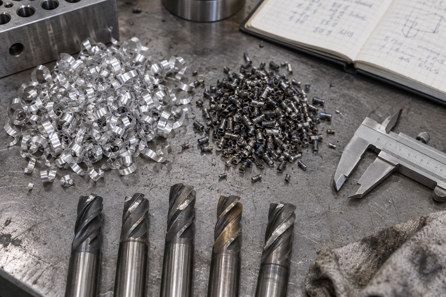
The second item is machining time. Cutting 6061 aluminum versus 304 stainless steel with the same tool involves completely different cutting parameters: stainless steel has a pronounced tendency to work-harden, requires slower feed rates, is harder to evacuate chips, and wears tools quickly—machining time can double or triple, and insert consumption is higher. Hardened steel and titanium alloys are even more extreme. So a "low material unit price" is often eaten up by "high machining cost." Conversely, there are cases where expensive material saves operations: some corrosion-resistant parts can be turned directly from stainless steel, eliminating the need for plating or coating—the saved operations and environmental handling costs may be more significant than the material price difference.
Heat treatment, surface treatment, gauges, and scrap rate: the hidden cost checklist
The third category is post-processing and verification. Heat treatment causes distortion, which requires leaving allowance, secondary fixturing, and even straightening; anodizing, plating, sandblasting, and passivation each have their own prerequisites and scrap risks. When sealing surfaces and mating surfaces require Ra 0.4 or finer, a separate precision grinding or lapping operation is often needed, along with dedicated gauges—the measuring instruments themselves are also a cost. Add in scrap during the debugging phase, first-article inspection, and batch sampling inspection, and these together often exceed the material cost.
So the correct approach is not to compare material unit prices, but to calculate per-piece cost by putting "material + machining time + tooling + post-processing + inspection + scrap" together, then amortize it over the batch. The smaller the batch, the higher the proportion of fixed costs (programming, fixturing, gauges), and material cost is not the focus; the larger the batch, the more material and tooling gradually become the dominant items. This is also why quoting off the top of your head based on material unit price is unreliable—quotes should be evaluated based on drawings, material condition, tolerances, and surface requirements together. When you need to make this step concrete, you can simply drop your drawings into the classic quote entry, letting the quote be broken down by process route rather than just giving a material price.
A few easy pitfalls: grade confusion, ignoring condition, grain direction and anisotropy
Even if the earlier screening layers are done correctly, things can still go wrong in the details. The real trouble in selecting materials for a part is often not in the big picture, but in those places that weren't clearly specified on the drawing and were taken for granted when reading the material table. The following types of misjudgments occur most frequently in prototyping and small batches.
Treating 6061 and 7075 as the same kind of "aluminum"
Both grades are called aluminum alloy, but their properties are far apart. A common industry situation is: 6061-T6 has a yield strength roughly in the 240–280 MPa range, with balanced machinability, weldability, and corrosion resistance, suitable for brackets, enclosures, and fixture base plates; 7075-T6 has a yield strength typically around 450–500 MPa, with hardness and strength approaching some steels, but it wears tools quickly during machining, is notch-sensitive, is almost never recommended for welding, and takes on a darker, grayer color after anodizing.
The consequences are direct: using 6061 for a cantilever part bearing high bending moment may lack sufficient stiffness and deform repeatedly; using 7075 for a frame that needs welding or a panel that needs inexpensive anodizing will run into cost and process obstacles. The verification action is simple—don't write "aluminum" on the drawing; write "6061-T6" or "7075-T6", and note whether substitute grades are allowed. The above values are only references for judging order of magnitude; the supplier's certificate of quality and the drawing shall prevail.
Ignoring heat treatment condition: the same grade, T6 and annealed are two different materials
The three characters "6061" don't carry enough information. 6061-O (annealed) is soft, easy to bend, and low in strength; 6061-T6 is hard and high in strength, but the bend radius must be increased, otherwise the outer surface is prone to cracking. The same goes for stainless steel—304 in cold-rolled and annealed conditions differs noticeably in bend springback and work-hardening tendency. For titanium alloys and some steel grades, the as-supplied condition (normalized, quenched and tempered, solution-treated) likewise directly determines whether precision machining can be done directly afterward.
The most easily overlooked thing here is that subsequent processes will change the state: welding softens the heat-affected zone, and residual stresses introduced by machining are released after material removal, causing warping. So on the drawing or process card, in addition to the grade, you must also clearly specify the supply condition, whether post-weld heat treatment is allowed, and the stress-relief arrangement before finish machining. Writing only the grade without the condition is equivalent to leaving the risk to the workshop.
Forgetting the anisotropy brought by rolling direction and fiber direction
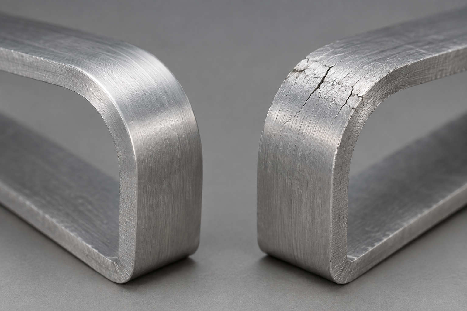
After rolling and extrusion, the grains in plates and bars are elongated along the flow direction, so the mechanical properties become directional. If the sheet metal bend line is parallel to the rolling direction, the probability of cracking on the outer surface is significantly higher than when it is perpendicular to the rolling direction. When designing bent parts, if conditions permit, make the bend line as perpendicular as possible to the sheet fiber direction, or appropriately increase the bend radius.
The anisotropy of additive manufacturing is even more prominent. The strength and elongation of FDM and some metal printed parts in the interlayer direction are usually lower than in the in-layer direction. If the load direction happens to fall between layers, the safety factor must be recalculated. In plastics, the fiber orientation of glass-fiber-reinforced parts follows the gate position and flow path. Long fibers significantly enhance performance along the flow direction, but much less so perpendicular to it. Check action: in drawings or process communication, mark the texture direction, bending direction, and principal load direction; do not let the workshop guess for you.
These three things: plastic water absorption, galvanic corrosion, and temperature softening
After nylon (PA) absorbs water, its dimensions swell and its rigidity decreases. For precision fitting parts, either choose a material with low water absorption (such as POM or PBT), or specify on the drawing the humidity conditions of the use environment and the allowable tolerance band. Galvanic corrosion occurs when two metals with a large potential difference are in direct contact and also encounter an electrolyte. Pay attention to combinations such as aluminum and steel, and stainless steel and carbon steel bolts; if necessary, use insulating pads, coatings, or choose materials with similar potentials to separate the pair.
The effect of temperature on plastics is often underestimated. ABS and PC, which are rigid enough at room temperature, begin to soften noticeably at 60–80 °C, and creep accelerates. When selecting plastic parts, write the maximum operating temperature into the requirements list, and then check the material's heat deflection temperature. This is much more reliable than looking only at room-temperature data. The common point of these pitfalls is that "the material itself is not wrong; it is the pairing and service conditions that were not clearly specified."
A screening sequence you can follow: from requirements to grade to verification
Bringing the previous layers together, how to select materials for a part can actually be gone through in a fixed order. If the order is right, even with insufficient experience it is hard to miss items; if the order is messy, it easily turns into aimlessly flipping through a material table. In the seven steps below, each step has a clear output. Finish one step before moving to the next.
- List service conditions—load type and magnitude, temperature range, medium, life requirement, assembly relationship. Output: a one-page requirements list.
- Determine failure modes—how it is most likely to fail: fracture, fatigue, wear-through, corrosion, deformation, creep. Output: a failure list ranked by priority.
- Set performance thresholds—translate failure modes into checkable indicators: tensile strength, fatigue limit, hardness, corrosion resistance grade. Output: an indicator table with numerical lower limits.
- Eliminate by geometry and tolerance—features such as thin walls, deep cavities, sealing surfaces, and fine threads will directly eliminate a batch of materials. Output: candidate materials reduced from a dozen or so to three to five.
- Select process by batch size—single pieces go to CNC or 3D printing, dozens to hundreds of pieces can consider silicone molding, and only tens of thousands of pieces justify injection molding. Output: process plan and corresponding material family.
- Compare cost—calculate blank utilization, machining hours, tool consumption, post-processing, and inspection, not just material unit price. Output: a comparison of two or three feasible plans.
- Validate with small samples—make prototype parts, measure key dimensions and function, and if necessary conduct salt spray or fatigue tests. Output: validation plan and release conclusion.
Among these seven steps, the fourth and fifth are the most likely to be repeated. If the geometry is too demanding, the process may need to be moved up a notch; if the batch size suddenly doubles, the material may also change from aluminum alloy to a cheaper plastic that requires a mold. Backtracking is allowed, but every backtrack must go through the failure modes again. Do not let any layer be quietly skipped.
What verifiable records should be kept at each step
The value of a screening sequence lies half in the process itself and half in the records it leaves behind. The requirements list must be traceable to the customer or use case; the metrics table must specify test standards or data sources; the process plan must note key constraints (such as minimum wall thickness and draft requirements); the validation plan must state what is being tested, what measuring instruments are used, and what the acceptance criteria are. When it comes to later revisions or switching suppliers, these records are far more reliable than verbal experience.
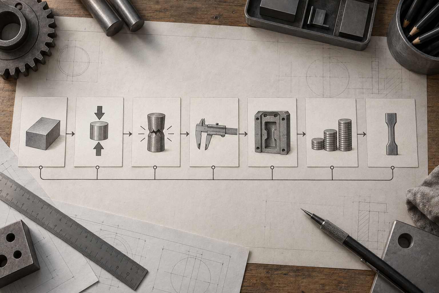
One final reminder: the material performance ranges, machinability assessments, and cost ranges commonly seen in the industry are only a starting point for judgment. The same grade in different batches, different conditions, or from different suppliers will have different measured values. The final selection conclusion must be based on drawing annotations, material certificates, and physical verification. When you need to turn a plan into a machinable part, you can first organize the drawings and operating conditions, then check process feasibility against the materials library or the manufacturing capabilities overview.
FAQ: Several high-frequency follow-up questions on material selection for parts
The previous sections broke down "how to select materials for a part" into several layers: failure modes, geometric tolerances, process volume, cost, and validation. Here we pick a few of the most frequently asked follow-up questions, and the ones easiest to answer incorrectly in a single sentence, and clarify the boundaries one by one.
Aluminum alloy or stainless steel: how do you quickly choose between the two?
First look at two questions: which matters more, weight or corrosion resistance. If you need to reduce weight, conduct heat, or apply anodized coloring, lean toward aluminum alloy; if you need corrosion resistance, wear resistance, or structural rigidity, lean toward stainless steel. The density of aluminum alloy is about one-third that of steel, but its elastic modulus is also lower, so it is "softer" at the same cross-section, and the cross-section must be thickened for long cantilevers or high-stiffness structures. Stainless steel has a pronounced tendency to work-harden, and its machinability is usually worse than aluminum alloy, with higher labor time and tool consumption. A common industry practice is: for bracket-type parts in non-corrosive environments where weight reduction is the main goal, use aluminum alloys such as 6061; for parts exposed to moisture, chemicals, or requiring wear-resistant mating surfaces, use stainless steels such as 304/316. Confirm the final choice according to the drawing and operating conditions.
Can plastic parts replace metal parts?
The scenarios where they can replace metal are usually: loads are not high, temperatures are not high, electrical and thermal conductivity are not required, and dimensional stability requirements are not strict. The advantages of plastics are self-lubrication, chemical resistance, the ability to injection-mold complex structures, and low unit cost. But the elastic modulus of plastics is one to two orders of magnitude lower than that of metals, and creep, water absorption, and thermal expansion are all more pronounced, so they will slowly deform under long-term load. Glass fiber reinforcement can improve rigidity and strength, but anisotropy is obvious, and shrinkage and warping are also harder to control. The way to judge is straightforward: list the actual load, operating temperature, and life requirements of the metal part, then compare them with the allowable stress and creep data of the plastic at that temperature. If you are unsure, do sample validation.
Without load data, how do you start selecting materials?
No data does not mean you cannot select, but you must first fill in the minimum inputs: where the part is installed, whether it is under tension, compression, or bending, whether there is impact, whether there is relative motion wear, and what the operating temperature and medium are. Even if you only give magnitude descriptions such as "the force of hand-tightening a bolt" or "the weight of a person stepping on it," that is better than being completely blank. To start, you can estimate a load based on the "worst case," multiply it by a safety factor, select candidate materials, and then do a trial fit or simple loading test on a sample. A reminder: estimates can only be used for preliminary screening and cannot replace design verification; the load conditions should be clearly stated on the formal drawing so that material selection has a basis.
What is the difference in material selection between small-batch and large-batch production?
The difference lies mainly in process constraints and cost structure. For one piece to a few dozen pieces, CNC and 3D printing can use almost any grade, giving high freedom in material selection, but you must accept higher per-piece labor time. For dozens to hundreds of pieces, vacuum casting (silicone mold duplication) can quickly replicate resins such as ABS-like and PP-like materials, suitable for appearance and assembly validation, but mechanical properties are usually lower than injection-molded parts. Only at tens of thousands of pieces do injection molding and die casting come into play; at that point the material must obey the mold: draft is required, shrinkage must be controlled, and excessively thick walls must be avoided, so material grades are often reverse-screened by shrinkage rate and flowability. Therefore, for the same part at different production volumes, the optimal material may not be the same.
On a drawing, is it enough to write only "steel" or "aluminum" for the material?
No, and it is one of the most common sources of rework. At minimum, write the grade plus condition, for example 6061-T6, 304, or 45 steel quenched and tempered. The condition directly affects strength, hardness, and machinability: annealed 6061 and T6 6061 differ greatly in performance, and the same grade after different heat treatments also behaves differently in machining. If there are directional requirements, the rolling direction or fiber direction must also be marked; if there are surface requirements, the roughness and treatment method must be clearly stated. When material information is incomplete, the processor can only use conventional default values, and the resulting part may fit but fail to meet the design intent. Completing the grade, condition, heat treatment, and surface treatment is the final step in putting material selection onto the drawing.
Key takeaways
- The order for choosing materials is "first define the failure mode, then define the performance threshold, and finally let process and cost eliminate candidates." Doing it in reverse usually leads to rework during prototyping or mass production.
- Metrics such as strength, hardness, corrosion resistance, and wear resistance must be tied to specific working conditions (load type, temperature, medium, service life). Discussing whether a material is "good" apart from the working conditions is meaningless.
- Tolerance, surface roughness, wall thickness, and structural features often determine the material earlier than strength does: too soft and it cannot be clamped, too hard and tooling costs rise, too brittle and edges chip easily. These are all common reasons for elimination.
- Batch size determines the process, and the process in turn locks down the material range: one-off parts go to CNC, dozens of parts can use vacuum casting, and only at tens of thousands of parts does injection molding or die casting become relevant. The material list expands or narrows accordingly.
- Any grade must be checked against the drawing to confirm temper (annealed/quenched and tempered/hardened), grain direction, heat treatment, and surface treatment requirements, and then the supplier should verify it against the actual part.