What Is Teflon (PTFE)?
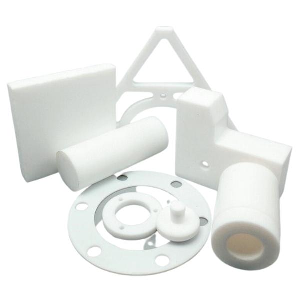
PTFE is both common and challenging in CNC machining: It is corrosion-resistant and has low friction, but it is also soft and prone to deformation. The chemical name of PTFE is polytetrafluoroethylene, a fluorinated thermoplastic engineering plastic. “Teflon” was originally a trade name and is now commonly used in everyday communication as a general term for PTFE, but engineering drawings and purchasing documents should still clearly specify the material type and exact grade.
The carbon chain in PTFE is surrounded by fluorine atoms, and its carbon–fluorine bonds are highly stable. This molecular structure makes it resistant to reactions with most chemical media while also giving it low surface energy and a low coefficient of friction. In mechanical design terms, this means parts are less likely to adhere to process media and are suitable for sliding, sealing, insulation, and corrosive environments. The trade-offs are poor bondability, while its rigidity and load-bearing capacity cannot be evaluated in the same way as those of metals.
- Virgin PTFE: Primarily retains fundamental properties such as chemical resistance, low friction, and electrical insulation, but offers limited creep resistance and dimensional stability.
- Modified PTFE: Certain properties are adjusted through changes to the material formulation. Its suitability cannot be determined from the term “modified” alone; grade-specific data must be reviewed.
- Filled PTFE: Fillers such as glass, carbon, or PEEK can be added to improve wear resistance, compressive strength, or dimensional stability, but friction, electrical properties, and chemical resistance may also change.
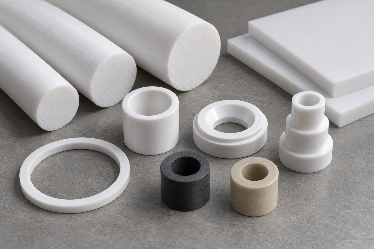
PTFE used for machining is typically supplied as rods, tubes, sheets, or compression-molded blanks. Even when materials share the same white appearance, different grades may vary in density, fillers, residual stress, and dimensional stability. Therefore, “machine it from Teflon” is not a complete material specification. When designing seal rings, bushings, or insulating parts, first confirm whether virgin or filled material is required, along with the operating temperature, sustained load, contact media, and inspection conditions, before determining the blank and CNC machining process.
Key Characteristics of Teflon in Machining
The advantages of Teflon (PTFE) go beyond simply being “corrosion-resistant and very smooth.” Each property affects part geometry, fit, and operating limits:
- Chemical resistance: PTFE is highly stable against strong acids, strong alkalis, and many organic solvents, making it suitable for seals, gaskets, and linings in chemical processing equipment. However, the medium concentration, temperature, and filler composition must still be verified when selecting the material.
- Low coefficient of friction: The material has pronounced self-lubricating properties and can be used for bearings, bushings, and sliding guides to reduce reliance on lubricants. However, low friction does not necessarily mean high wear resistance; wear and creep must also be evaluated under sustained loads.
- Wide service temperature range: Common reference data specify a continuous service temperature range of approximately -200℃ to 260℃, making PTFE suitable for isolation and sealing parts in both hot and cold environments. The actual limits depend on the material grade, load, medium, and service-life requirements.
- Good electrical insulation: PTFE is commonly used for insulating mounts, isolation sleeves, and electrical and electronic parts. However, insulation clearances, wall thickness, operating frequency, and ambient temperature must still be determined according to product requirements.
- Low surface energy and low adhesion: This property facilitates part release, resists contamination, and reduces medium residue, but it also makes adhesive bonding difficult. When bonding is required, the surface treatment, primer, and adhesive system generally need to be validated, or mechanical fastening should be used instead.
- Weathering and aging resistance: PTFE is generally stable outdoors and in long-term exposure environments, making it suitable for isolation and sealing parts intended for extended service. However, resistance to radiation, mechanical fatigue, and high loads cannot be determined solely from its “aging resistance.”
These properties also come with trade-offs: virgin PTFE has relatively low mechanical strength and rigidity, and its dimensions are easily affected by load, temperature, and measurement force. When designing machined Teflon parts, low friction and chemical resistance must be weighed against creep, deformation, and bonding difficulties. PTFE should not be treated as a direct substitute for metal.
Why Is Teflon CNC Machining So Difficult?
The challenge of Teflon CNC machining is not that the material is too hard, but that it is too soft and readily changes shape under pressure and temperature. Creep, heat buildup, low rigidity, and smearing during cutting can also amplify one another, so machining parameters and inspection practices used for metals such as aluminum alloys cannot be applied directly.
PTFE Creep: Dimensions Change Gradually Under Load
Problem: A part may meet dimensional requirements after machining but deform after being subjected to sustained pressure. Cause: PTFE is prone to creep under clamping force, measurement force, or operating loads. Solution: Avoid heavy clamping for extended periods, control the measuring force of inspection tools, and evaluate dimensions based on the part’s actual temperature, load, and assembled condition.
Poor PTFE Thermal Conductivity: Cutting Heat Becomes Localized
Problem: The machining area may soften and expand, then shrink again after cooling. Cause: PTFE conducts heat slowly, so heat generated by tool friction cannot dissipate quickly. Solution: Limit heat input from continuous cutting, evacuate chips promptly, and provide supplemental cooling. After finishing, allow the part temperature to stabilize before inspection.
Low PTFE Rigidity: Thin Walls Easily Deflect and Become Distorted by Clamping
Problem: Thin walls, long overhangs, and small features are prone to vibration, deflection, or loss of roundness. Cause: The material’s low rigidity allows both cutting and clamping forces to displace the workpiece from its theoretical position. Solution: Minimize workpiece and tool overhang, increase the clamping area, and add conformal support near thin walls or cavities.
Cutting Tends to Smear the Material: Rolled Edges and Burrs Are Difficult to Avoid
Problem: Rolled edges, stringing, and burrs around hole openings may occur. Cause: A dull tool tends to push and smear PTFE rather than cutting it cleanly. Solution: Keep cutting edges sharp and use an appropriate feed rate to avoid repeated rubbing. The design should also provide accessible deburring space around sealing lips, mating edges, and deep holes.

These issues usually do not occur in isolation: clamping deformation changes the machining allowance, while heat buildup further aggravates tool deflection and smearing. Stable Teflon CNC machining requires the material condition, workholding, cutting tools, heat, and measurement methods to be managed as one integrated process system.
Workholding, Cutting Tool, and Parameter Tips for Machining Teflon
Cutting Tools for Teflon Machining: Edge Sharpness Matters More Than Hardness
Machining Teflon generally calls for sharp carbide cutting tools with positive rake angles and ample chip-clearance space. Dull cutting edges tend to push the material, leaving stringing, rolled edges, and smeared surfaces. A larger nose radius can be selected when turning profiles, depending on the surface requirements, but a larger radius generally produces higher radial cutting forces. When machining thin-walled rings or slender bushings, this may instead aggravate tool deflection and part deformation.
Teflon CNC Machining Parameters: Control Heat and Maintain Effective Cutting
A common recommendation in technical references is to use “relatively low speeds and assertive feed rates”: this reduces unnecessary frictional heat while allowing the cutting edge to cut into the material rather than repeatedly rub against the surface. This is not a fixed formula; spindle speed and feed rate must still be tested and adjusted according to the workpiece diameter, wall thickness, number of cutting edges, and tool overhang. Coolant or compressed air can help remove heat and chips, but the medium should be verified to ensure that it will not contaminate the part and is compatible with subsequent cleaning and the service environment.
Workholding for Machining Teflon: Increase the Load-Bearing Area and Support Close to the Cut
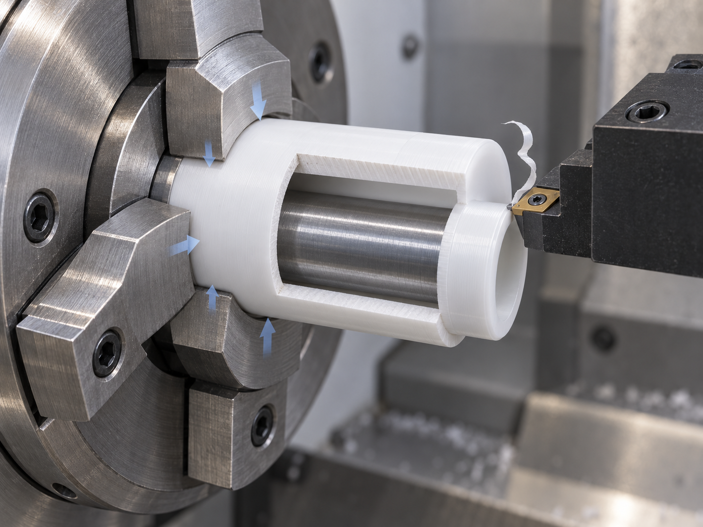
Excessive clamping force can leave jaw marks, distort round parts into an oval shape, or temporarily collapse thin-walled structures. Soft jaws, wraparound clamping jaws, or custom fixtures can be used to increase the contact area, with additional local support placed near the cutting zone. Clamping force should be only high enough to locate the part securely without slippage; settings used for metal parts should not be copied directly. Dimensional requirements should also allow for material springback, creep, and temperature changes. As a preliminary estimate, the industry often begins by evaluating Teflon machining tolerances in the range of approximately ±0.1 mm to ±0.2 mm, but this is not a universal capability value and must be verified based on the part geometry, datums, service temperature, and inspection method.
Common Teflon Machining Processes: Turning, Milling, and Drilling
Turning Teflon: Preventing Thin-Wall Deformation and Chip Entanglement
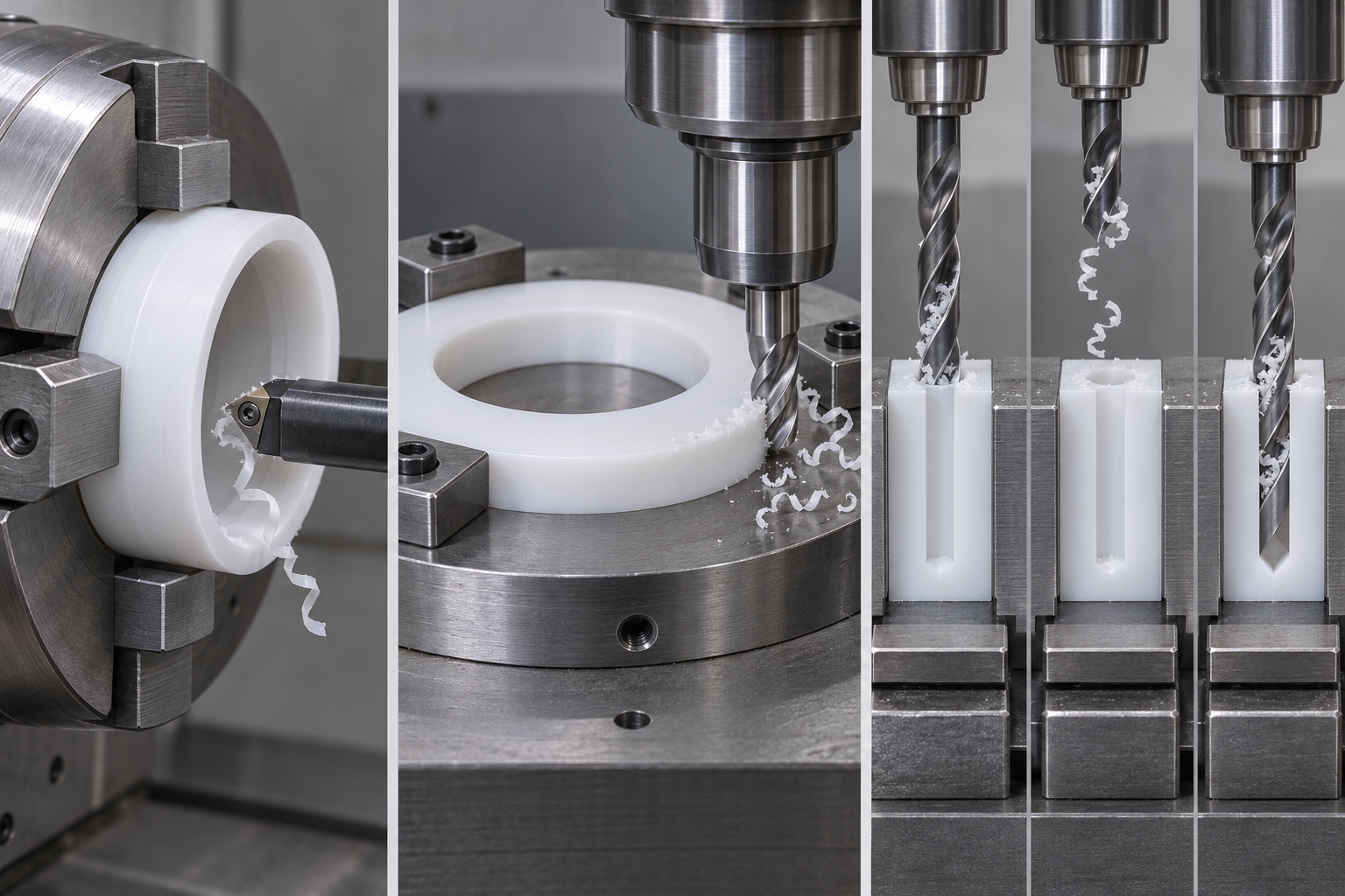
Turning is suitable for machining sealing rings, washers, bushings, and rotationally symmetrical valve components. PTFE has low rigidity, so thin-walled workpieces can easily be clamped into an oval shape by the chuck and may also deflect away from the tool under cutting forces. The clamping area should therefore be increased, clamping force controlled, and workpiece overhang minimized. Sharp cutting edges help sever the material cleanly and prevent surface compression and smearing. Continuous ribbon-like chips can also wrap around the workpiece or cutting tool and must be managed through suitable feed rates, chip-breaking methods, and prompt chip removal. Parting operations often leave rolled edges on the end face. These should be carefully removed before dimensional inspection without damaging the sealing lip.
Milling Teflon: Support Matters More Than Parameter Adjustments Alone
Milling is commonly used for insulating plates, slide blocks, valve seats, and irregular profiles. If plates or long, narrow parts are inadequately supported, they can bend downward during cutting and spring back after the fixture is released, causing flatness and profile dimensions to deviate from expectations. A flat backing plate, soft jaws, or a custom fixture should be used to provide continuous support, while tool overhang should be minimized. Tool deflection is especially likely at internal corners, narrow slots, and thin-walled corners. Efficiency should not be increased solely by increasing the depth of cut; layered cutting can be used, with a uniform allowance reserved for finishing.
Drilling Teflon: Controlling Rolled Edges, Springback, and Heat Buildup in the Hole
The main issues in drilling are rolled edges at the hole entrance, bore-diameter springback, and poor chip evacuation. A dull drill tends to push the material toward the edge of the hole rather than produce a clean cut. If chips cannot escape from a deep hole, they will rub against the hole wall and accumulate heat. Sharp drills and peck drilling are generally recommended for chip evacuation, supplemented when necessary by a compatible coolant or compressed air. A reliable backing support should be placed at the exit of a through-hole to reduce breakout and burrs. The final hole diameter should not be determined while the workpiece is still hot or affected by clamping force.
Process sequencing also affects the outcome: Machine stable datum features and the main profile first, followed by deformation-prone features such as thin walls, narrow grooves, and small holes; finally, leave sufficient access for manual edge finishing and inspection. This makes cumulative deformation easier to control than repeatedly clamping a flexible part after it has been formed.
Dimensional Inspection and Deburring After Teflon Machining
When PTFE parts first come off the machine, they may still retain cutting heat and clamping stresses. Diameters, flatness, and hole sizes may change slightly after the material cools, springs back, or releases stress. Therefore, immediate readings are suitable for process monitoring but should not be used directly as the basis for final acceptance.
PTFE Machined Dimensions Should Be Measured Under Stable Conditions
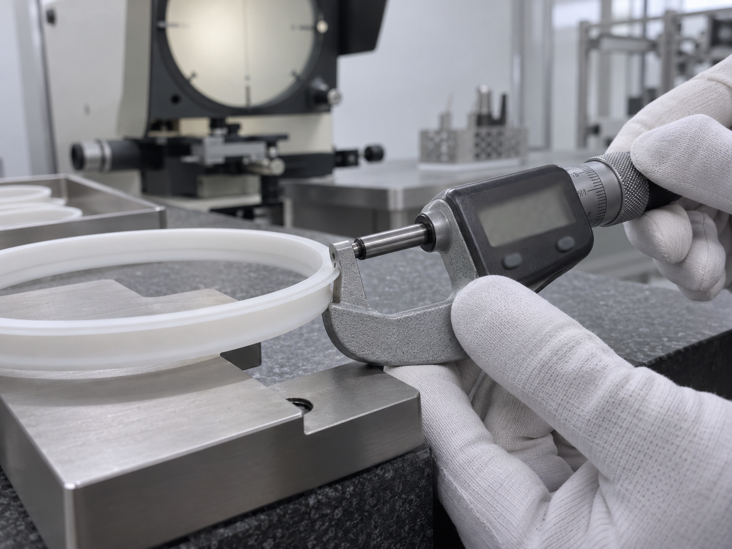
Before inspection, the measurement temperature, stabilization time, and support method should be defined according to the drawing or inspection specification, and the workpiece and measuring instrument should be kept at similar temperatures. Measuring force must also be controlled when using calipers or micrometers: excessive pressure may compress thin walls, sealing lips, or soft rings, producing dimensions that appear “acceptable” but are inaccurate. For thin-wall rings, flexible gaskets, and critical profiles, limit gauges, low-force measuring instruments, vision measurement systems, or other non-contact methods may be used. The temperature, measurement points, and measurement method should be recorded in the report to facilitate verification.
Deburring Teflon Parts Must Not Damage Functional Edges
Raised edges and stringy burrs produced during Teflon machining are usually soft and are commonly removed by hand scraping, precision edge finishing, or localized treatment under magnification. The tool should cut lightly along the root of the burr to avoid stretching the material outward. Hole edges should be inspected individually, and oversized chamfers must not be used to conceal burrs. Sealing lips, mating edges, valve-seat contact lines, and insulation clearances are functional features; their profiles and dimensions should be inspected again after deburring.
Chemical deburring, bead blasting, and precision finishing after cryogenic treatment are not suitable for every PTFE part. Before these methods are used, sample parts should be tested to verify the material grade, wall thickness, cleanliness, surface roughness, and residue risks. Parts intended for medical, food-contact, or high-purity fluid applications should also be checked against the applicable requirements. Acceptance criteria should clearly define the permissible burr condition, the required treatment of sharp edges, and areas that must not be touched, rather than simply stating “remove all burrs.”
Typical Applications and Alternative Materials for Machined Teflon Parts
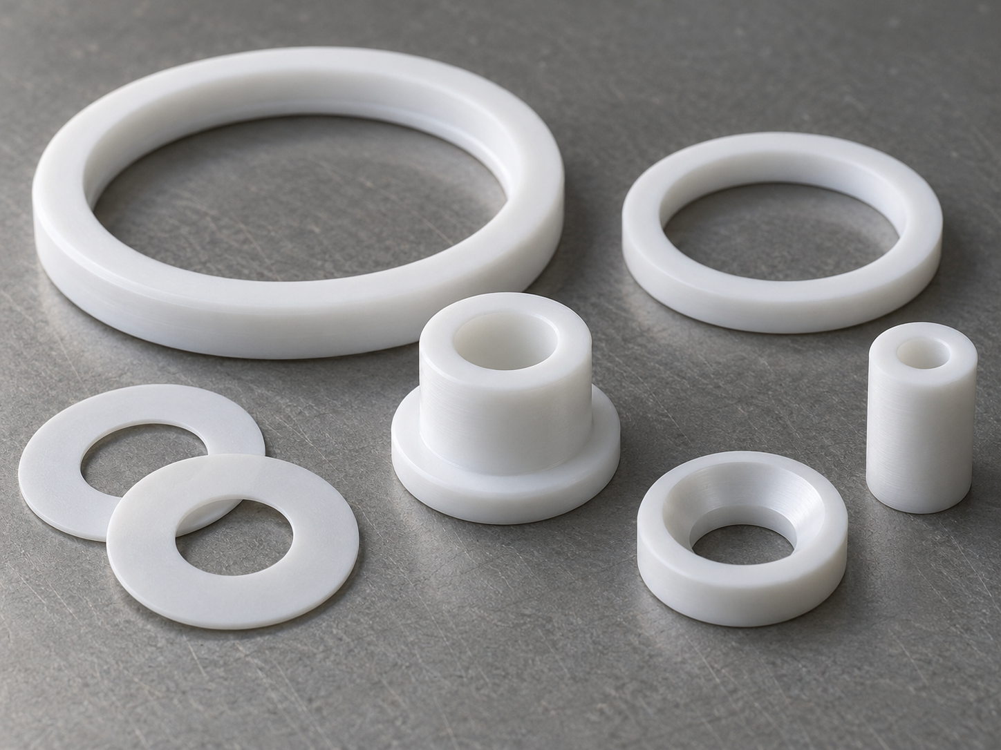
The value of machined Teflon parts usually lies not in carrying high structural loads, but in simultaneously addressing friction, corrosion, adhesion, or electrical insulation requirements. Common applications include:
- Automotive and general machinery: Used for low-friction bushings, lightly loaded gears, and valve components to reduce dependence on lubrication, although loads and creep must be evaluated.
- Chemical processing equipment: Used for seals, gaskets, and corrosion-resistant linings, and suitable for environments involving contact with various acids, alkalis, and organic solvents.
- Medical equipment: Used for valves, needle housings, and insulating components; the specific material grade, cleanliness, and biocompatibility must still comply with the applicable requirements.
- Food processing equipment: Low surface energy helps reduce material adhesion and is useful for sliding components, guides, and seals, but the material’s food-contact compliance must be verified.
- Electronics and electrical equipment: Used for insulating mounts, spacers, and certain high-frequency components. Temperature, dielectric properties, and dimensional stability must also be evaluated during design.
How to Choose Between Virgin PTFE and Filled PTFE
Virgin PTFE is better suited to applications where chemical inertness, low friction, and electrical insulation are the primary considerations. Adding fillers such as glass, carbon, or PEEK can generally improve wear resistance, compressive strength, or dimensional stability, making the material more suitable for load-bearing bushings and wear parts. However, fillers may also alter friction characteristics, electrical properties, surface condition, and chemical resistance, so filled PTFE should not simply be regarded as a “comprehensive upgrade.” When selecting a material, verify the filler type and percentage, contact media, and operating loads.
Criteria for Selecting Alternatives to Teflon
Fluoropolymers such as PCTFE, ECTFE, and PFA can be considered as alternatives, but they emphasize different performance characteristics: some prioritize rigidity or low permeability, while others are more suitable for melt processing. Comparisons should consider operating temperature, media, permeability requirements, rigidity, processing method, and cost rather than focusing solely on whether the material is “fluorinated.” PTFE offers excellent low-friction and chemical-resistance properties, but it is also relatively difficult to process and has higher creep risks and material costs, requiring trade-offs in design and manufacturing.
Common Issues in Teflon Machining
Tolerances, dimensional changes, and joining performance in Teflon machining cannot be evaluated solely based on machine tool accuracy. Material grade, ambient temperature, workholding method, measurement force, and service loads can all affect the results. The following four questions can be used for drawing reviews and process discussions.
Can Teflon Parts Be Specified with the Same Tight Tolerances as Aluminum Alloy Parts?
In general, tolerances for aluminum alloy parts should not be applied directly to PTFE parts. PTFE has low rigidity and is prone to creep, while thin walls, long overhangs, and large structures are also affected by clamping forces and cutting heat. Industry evaluations often begin with tolerances of approximately ±0.1 mm to ±0.2 mm, but this is not a universal capability range. Critical mating dimensions should be verified through trial machining based on the part geometry, material grade, measurement temperature, and workholding plan.
Why Do the Measured Dimensions of Teflon Parts Change After CNC Machining?
Common causes include residual cutting heat, the release of clamping stress, material creep, and localized compression of the part due to measuring force. A dimension that is within tolerance immediately after machining may shrink after cooling or resting. Thin-walled rings may also recover from a circular shape under clamping to an oval shape after release. Inspection conditions should be standardized, including resting time, ambient temperature, support method, and measurement force. Dedicated gauges or non-contact measurement should be used when necessary.
How Should Virgin PTFE and Filled PTFE Be Selected?
When chemical inertness, low friction, and electrical insulation are priorities, virgin PTFE should be evaluated first. For applications involving sustained pressure, friction and wear, or greater dimensional stability, PTFE filled with glass, carbon, or PEEK can be considered. Fillers may improve compressive strength, wear resistance, and creep resistance, but they can also alter friction characteristics, electrical properties, surface condition, and chemical resistance. The final selection should be confirmed using data for the specific grade and the actual media, temperature, and loads.
Can Adhesive Bonding Be Used for Machined Teflon Parts?
It can be attempted, but ordinary adhesive bonding should not be treated as a reliable default solution. PTFE has low surface energy, so most adhesives cannot adequately wet or adhere to untreated surfaces. Specialized surface treatment, primers, or compatible adhesives are usually required. The results are also affected by the material grade, surface cleanliness, joint design, temperature, and media. Test specimens should be produced to validate load-bearing or sealing joints. Where conditions permit, mechanical fastening, press fits, or mechanical interlocking can also be considered.
Key takeaways
- PTFE's low friction, chemical resistance, and electrical insulation properties make it suitable for seals, bushings, valve components, and insulating parts.
- Creep, low rigidity, poor thermal conductivity, and smearing during cutting are the main challenges in Teflon CNC machining.
- Sharp tools, stable support, light clamping, and adequate cooling are generally more important than simply pursuing high cutting speeds.
- PTFE dimensions are affected by temperature, load, and the timing of measurement, so tolerances must be determined based on the part design and service conditions.
- Filled PTFE can improve wear resistance, compressive strength, or dimensional stability, but it may also alter friction, electrical insulation, and chemical resistance.