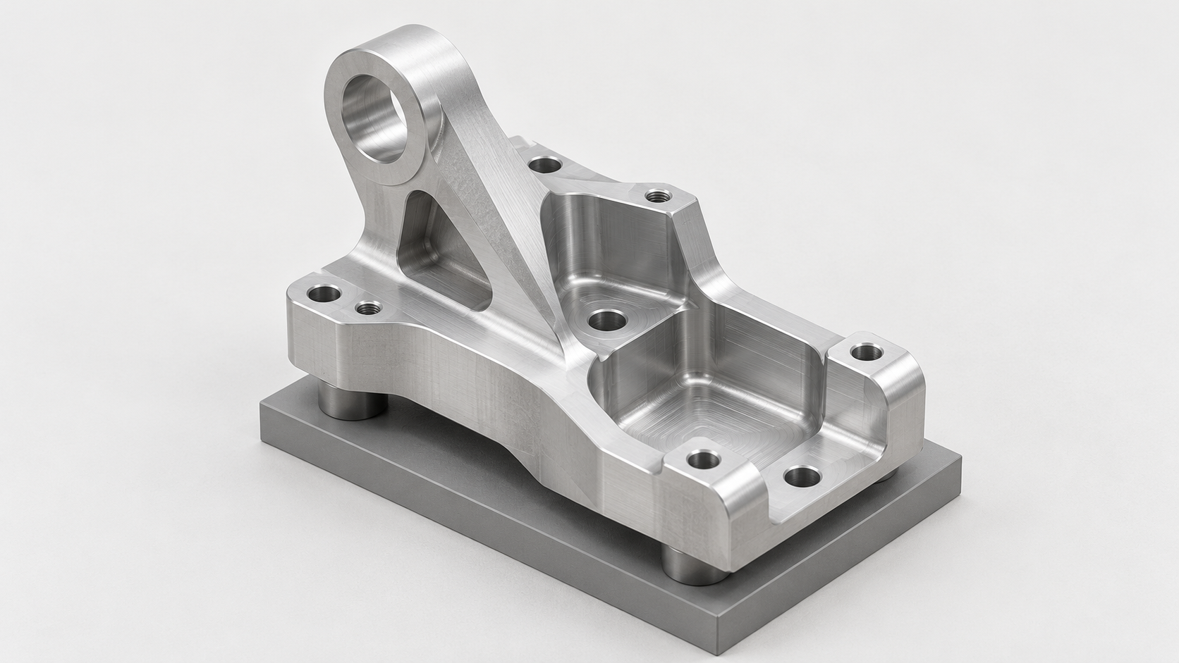
Why CNC Machining Complex Irregular Workpieces Is Difficult: Datums, Accessibility, and Deformation Risks
The difficulty of machining irregular workpieces usually lies not in “whether five-axis machining is possible,” but in whether stable datums can be established within a limited number of fixturing operations and whether critical dimensions can ultimately be measured repeatably. Equipment brackets or robotic connectors with irregular curved surfaces, angled holes, deep pockets, and multiple datum faces often face four risks simultaneously: inaccessible geometric features, insufficient fixturing rigidity, localized deformation after cutting, and non-repeatable measurement datums.
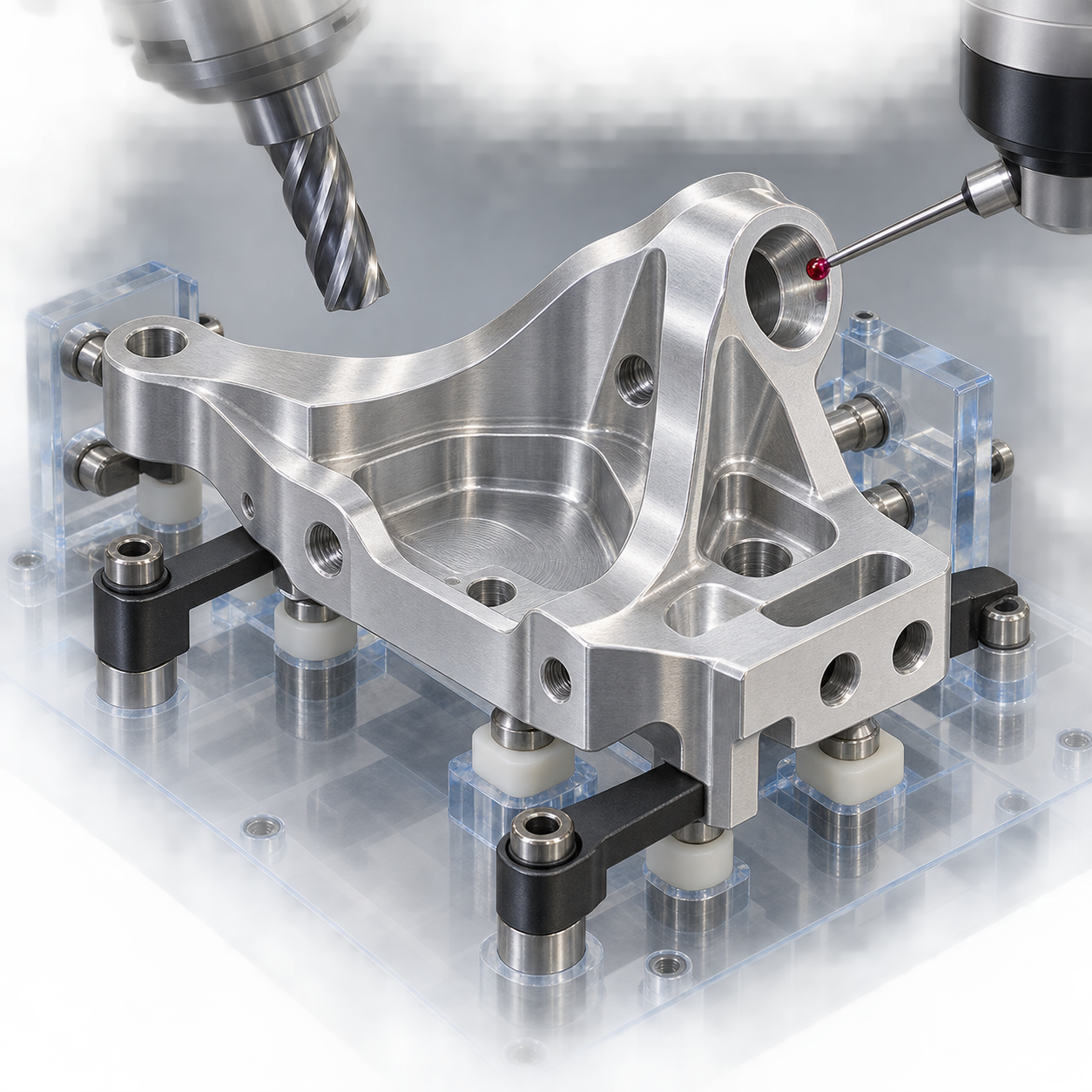
Four Risks to Assess First When CNC Machining Irregular Workpieces
Geometric accessibility determines whether the tool can approach angled holes, pocket bottoms, or undercut areas; the fact that the tool can “reach” a feature does not mean there is no interference between the tool holder, fixture, and workpiece. Fixturing rigidity determines whether vibration will occur during cutting, with particular attention required for thin walls, curved surfaces, and unsupported areas. Cutting deformation may result from clamping forces, residual stress, excessive tool overhang, or overly rapid local material removal, and the part may spring back after being removed from the machine. Measurement repeatability requires a clear datum system to be maintained during inspection; otherwise, even if the measuring instrument readings appear normal, it is difficult to determine whether hole positions, curved surfaces, and relative locations truly meet requirements.
Therefore, the process sequence should be to stabilize the datums first, then stabilize the toolpaths, and finally verify them using an appropriate inspection method. First identify the primary datums, secondary datums, critical hole positions, and functional curved surfaces from the 2D drawing and 3D model, then check whether the fixturing areas avoid weak surfaces and surfaces to be machined. Next evaluate tool orientation, overhang, chip evacuation, and local interference, and finally define inspection datums for critical dimensions in advance. Five-axis machining may reduce some repeated fixturing operations, but it does not automatically eliminate errors caused by the machine tool, fixture, cutting tool, or measurement conditions.
Choosing Three-Axis, 3+2, or Five-Axis Machining: Determine the Method Based on Irregular Workpiece Features
CNC machining of irregular workpieces should not begin by asking “Is five-axis machining required?” Instead, first check whether the features can be approached reliably. The usual evaluation sequence is to identify the machined surfaces and datums, check tool accessibility, and then assess the number of fixturing operations, tool orientation, material removal volume, and dimensional tolerances. The potential of five-axis machining to reduce repeated fixturing operations is meaningful only when the part structure genuinely requires access from multiple directions; reducing the number of fixturing operations does not mean that errors disappear.
How to Choose Among Three-Axis, 3+2, and Simultaneous Five-Axis Machining
| Process Method | More Suitable Features | Key Inspection Points |
|---|---|---|
| Three-axis | Planes, steps, holes in a single direction, and relatively simple curved surfaces | Whether multiple reorientations are required and whether datum errors after reorientation are acceptable |
| 3+2 indexing | Inclined surfaces, multidirectional holes, and localized curved surfaces requiring a fixed tool orientation | Datums after indexing, rotary-axis positioning, and fixture interference |
| Simultaneous five-axis | Continuously complex curved surfaces, undercuts, deep cavities, and areas requiring frequent directional changes | Changes in tool orientation, localized interference, machine-tool rigidity, and post-processor reliability |
For irregularly shaped workpieces with many planar surfaces and limited directional features, three-axis machining can be evaluated first, with machining completed through appropriate zoning and fixture design. When inclined holes, compound angles, or multiple sides require repeated repositioning, 3+2 indexing is often more direct than continuous simultaneous machining: first adjust the B/C axes to fixed angles, then use the linear axes to perform the cutting. Simultaneous five-axis machining is more worth evaluating only when the tool must continuously change orientation along a curved surface, or when three-axis and 3+2 machining would result in excessive setups and tool overhang.
Equipment configuration, in turn, affects fixturing and accessibility
The configuration of five-axis equipment should also be incorporated into process decisions. A trunnion-style or rotary table generally makes it easier to keep the workpiece fixed and may benefit rigidity and heavy cutting, but the table load capacity, rotary clearance, and workpiece envelope must be verified. A tilting-head configuration may provide more flexible access for larger or heavier workpieces, but changes in tool orientation, overhang, and machine-tool rigidity require separate verification. The final choice still depends on the part size, material, fixture, production volume, and drawing tolerances—not the number of axes itself.
Positioning and fixturing of irregularly shaped workpieces: how to plan datums, support points, and clamping force
Positioning and fixturing of irregularly shaped workpieces should not begin with “where is it convenient to clamp?” Instead, return first to the drawing and 3D model: identify the primary datum, secondary datums, critical holes, critical curved surfaces, and which surfaces must be machined within the same datum system. For an equipment bracket with inclined holes, curved surfaces, and deep cavities, re-establishing alignment from scratch after every setup change can cause the positional relationships between holes and curved surfaces to accumulate fixturing errors. The primary task of the fixturing plan is to ensure that the same coordinate relationship can be reproduced during machining, measurement, and reorientation.
Positioning and fixturing of irregularly shaped workpieces: determine the datums and machining sequence first
Typically, first select a stable datum surface with good rigidity, then use holes, side surfaces, or locating pins to establish secondary constraints. Locating points should be kept away from surfaces to be machined later, thin-wall areas, and edges prone to collapse. The machining sequence must also be coordinated with the fixturing design: first machine the datums that can serve as references for subsequent positioning, then process the critical holes and main external features, and finally machine thin-wall or unsupported areas that are prone to deformation. If the workpiece does not have sufficient planar surfaces, soft jaws, contoured supports, auxiliary supports, or dedicated fixtures may be evaluated, but the specific choice depends on the material, wall thickness, curvature, and cutting loads.
Clamping force and support for irregularly shaped workpieces must be considered for both machining and the post-machining state
Curved parts, thin-walled parts, or castings cannot be approached with the sole aim of “clamping them tightly.” Excessive local clamping force may cause indentations, cross-section distortion, or false dimensions during machining; after the fixture is released, elastic springback may cause the dimensions to change again. Support points should be positioned close to the cutting-force area, with clearance reserved for the tool, probe, and chip evacuation, while avoiding the application of pressure to critical finish-machined surfaces. During process review, the clamped condition and the unloaded free condition should be checked separately: where necessary, compare the critical dimensions in both conditions to confirm that the inspection datum, support method, and clamping force do not conceal the actual deformation.
- 定位:主基准、辅助基准和关键孔位是否能重复找正。
- 刚性:切削力、刀具悬伸和薄壁区域是否有足够支撑。
- 干涉:夹具、压板、定位件是否妨碍刀具、测头或排屑。
- 变形:夹紧状态与下机自由状态的尺寸差异是否已纳入检测方案。
From Roughing to Surface Finishing: Toolpath and Tool-Orientation Planning for Irregular Workpieces
The toolpath for an irregular workpiece cannot be generated based solely on its external shape. For parts with deep cavities, thin walls, or continuous curved surfaces, pursuing finishing from the outset can easily lead to vibration and deformation due to uneven stock, inadequate support, or excessive tool overhang. A more reliable approach is to arrange machining in stages—roughing—semi-finishing—finishing—while keeping the fixturing plan, stock allocation, and tool orientation consistent.
Roughing and Semi-Finishing: Remove Stock Stably First
The purpose of roughing is to safely remove most of the material, not to obtain the final profile in a single operation. The toolpath should avoid sudden localized increases in engagement, cutting with excessive overhang, and the premature loss of support in thin-walled areas; for deep cavities, chip evacuation, tool-holder interference, and cutting heat must also be considered. Semi-finishing should make the remaining stock relatively uniform, establishing controllable contact conditions for subsequent surface finishing. If the remaining material is noticeably thicker in one area, finishing may cause sudden load changes, more pronounced tool marks, or dimensional deviation.
Surface Finishing: Plan Tool Orientation According to Curvature and Contact Conditions
For gently curved surfaces, parallel, constant-z, or 3D offset toolpaths can generally be evaluated; in areas with significant curvature changes, check whether the tool contact point remains stable and whether adjacent toolpaths produce pronounced tool marks. For deep cavities, undercuts, or compound angles, 3+2 positioning or simultaneous five-axis machining may improve tool orientation, but five-axis machining is not the default solution. The value of adding axes lies in allowing the tool to approach the surface at a more suitable angle; it does not mean that fixturing errors, tool runout, or thermal deformation can be eliminated.
Industry literature often presents a high-speed machining approach based on a smaller radial depth of cut, suitable cutting speeds, and appropriate feed rates to reduce cutting forces, heat accumulation, and the risk of burrs. However, specific parameters can only serve as a starting point for trial cutting and must be validated in combination with the material, tool diameter, machine-tool rigidity, and fixturing condition. When machining irregular workpieces, program review should at minimum check tool overhang, localized overcutting, tool-holder and fixture interference, stock distribution, vibration, burrs, and the final surface texture; simulation showing that the tool “can reach” the area must still be followed by trial cutting to confirm stable cutting.
- Roughing: Confirm that material removal is uniform and prevent thin walls from losing support prematurely.
- Semi-finishing: Uniformize stock on curved surfaces and in cavities to reduce sudden load changes during finishing.
- Finishing: Verify tool orientation, contact conditions, remaining stock, tool-mark direction, and critical surface tolerances.
- Trial cutting or first article: Compare the actual dimensions and surface condition, and revise the toolpath, supports, or tool overhang as necessary.
Angled Holes, Deep Cavities, and Undercut Features: Machining Accessibility and Interference Checks
For local features on irregular workpieces, the challenge is not merely whether the tool can “reach” the machining area; it also includes whether the tool orientation is stable, whether the cutting force is controllable, and whether the tool holder and fixture will interfere. Programming reviews should assess accessibility, stable machining, and final inspection separately; conclusions should not be based solely on visual checks in the 3D model.
Angled Holes in Irregular Workpieces: First Confirm the Hole Axis and Entry Datum
Before machining an angled hole, clearly define the hole-axis direction relative to the primary datum, the normal direction of the entry face, the hole-bottom form, and the positional tolerance. Whether drilling or milling is used, the tool axis must correspond to the design direction; if the fixturing orientation is unsuitable, the tool may be able to approach the hole entrance but be unable to maintain a stable orientation. Hole position and inclination are relational dimensions, so final inspection is generally better performed with a vision measuring system or CMM rather than by measuring only the hole entrance with calipers.
Deep Cavities and Undercuts in Irregular Workpieces: Check Tool Overhang, Chip Evacuation, and Envelope Interference
Deep-cavity machining requires simultaneous evaluation of tool overhang, tool runout, chip evacuation space, cavity-bottom radii, and residual-stock distribution. Simply extending the tool may increase the reachable depth, but it can also amplify vibration, tool deflection, and dimensional deviations. For undercuts or compound angles, check the motion envelope of the tool holder, tool body, fixture, and workpiece to confirm that no collisions occur during direction changes.
After simulation is completed, residual stock, overcut risk, tool marks, and critical surface quality should also be verified. If the tool orientation remains consistently unfavorable, first consider redefining the fixturing direction, or evaluate options such as 3+2 indexing and simultaneous five-axis machining. The value of five-axis machining lies in improving reachability and orientation control; it does not automatically eliminate fixturing errors. After trial cutting or first-article machining, actual residual stock, vibration, and dimensional results should be fed back into toolpath corrections.
Dimensional Inspection and Delivery Documentation for Irregular Workpieces: Making Results Reproducible
Inspection of irregular workpieces should not be performed only after machining is complete. First-article inspection should first confirm that the datum system, fixturing orientation, and toolpath conform to the drawing; in-process inspection is used to track critical dimensions, hole locations, and deformation in thin-wall areas; final inspection should select measuring instruments based on the tolerances and geometric features. Only in this way can differences in results be distinguished as machining deviations, fixturing springback, or inconsistencies in measurement datums.
Dimensional Inspection of Irregular Workpieces Should Match the Features and Tolerances
For ordinary outside diameters, inside diameters, or length dimensions, conventional measuring instruments such as calipers and height gauges can be evaluated first; in the industry, dimensions of approximately ±0.05 mm or looser are often considered within the evaluation range for calipers. Dimensions of approximately ±0.01–0.05 mm are generally more suitable for verification with micrometers or inside micrometers. For tighter tolerances, hole-location relationships, inclined-hole axes, and complex surfaces, consider an optical measuring instrument or CMM, and clearly specify the measurement datum, fixturing orientation, and evaluation method in the report. These ranges are only references for process judgment, not universal acceptance standards; actual suitability is also affected by the dimensional range, instrument resolution, temperature, and operator.
Clarify Datums, Critical Features, and Inspection Requirements Before Delivery
For outsourced machining, do not simply send a CAD file and require the supplier to guarantee the dimensions independently. The documentation should include at least:
- 2D drawings and 3D models, along with primary datums, secondary datums, and critical-feature identifiers;
- Dimensional tolerances, geometric tolerances, material condition, surface treatment, and critical surface requirements;
- Inspection methods and measurement datums for high-risk features such as inclined holes, deep cavities, and thin walls;
- First-article approval milestones, in-process inspection items, the final inspection report format, and whether dimensional records are required.
A review table can be established using “feature—risk—process—inspection”: for inclined holes, address tool reachability and hole-axis deviation, with particular attention to indexing or five-axis positioning and the results from an optical measuring instrument or CMM; for thin-wall surfaces, address clamping deformation by comparing dimensions in the clamped and free states; for multiple-face datums, focus on accumulated errors from repeated fixturing and ensure that final inspection uses the drawing’s datum system. For irregular workpieces, the inspection plan is not a remedial measure after delivery, but part of the fixturing and machining decisions.
Common Questions About CNC Machining of Complex Irregular Workpieces
For CNC machining of complex irregular workpieces, the key considerations are not based solely on the number of machine axes, but on returning to datums, rigidity, tool orientation, tolerances, and measurement conditions. The questions below address the engineering decisions most easily confused among three-axis, 3+2, five-axis, fixturing, and inspection.
Is Five-Axis Machining Necessarily More Accurate Than Three-Axis Machining?
Not necessarily. Five-axis or 3+2 machining may reduce some repeated fixturing operations and improve tool reachability for inclined surfaces, inclined holes, and complex surfaces, but actual dimensional results are still affected by machine rigidity, fixtures, tool runout, thermal deformation, and measurement datums. If the part consists mainly of planar surfaces and a small number of directional features, a properly fixtured three-axis process may be more suitable.
Does a Single Fixturing Operation Mean Zero Error?
No. A single fixturing operation can only reduce error sources caused by repositioning; it cannot eliminate tool wear, cutting deformation, clamping deformation, machine errors, or measurement errors. For irregular workpieces, the locating surfaces, support points, tool interference, and dimensions in the free state after removal from the machine must still be confirmed.
Must complex curved surfaces be machined using five-axis machining?
Not necessarily. First check surface accessibility, tool overhang, surface texture, and the number of setups required. Some curved surfaces can be completed using three-axis or 3+2 machining; when continuous surfaces, undercuts, deep cavities, or frequent direction changes are involved, and it is difficult to ensure the required fixed tool orientation, simultaneous five-axis machining offers greater process value.
Why do thin-walled curved surfaces require conformal or auxiliary support?
Thin walls or castings are prone to local deformation during clamping and cutting. Conformal supports, soft jaws, or auxiliary supports can improve rigidity at appropriate locations, but the support surfaces must not press against critical surfaces or weak areas. It is also necessary to verify whether springback occurs after the fixture is removed. The specific solution should be confirmed based on the part structure and machining sequence.
How should the inspection method be selected for angled holes and complex hole locations?
First clarify the hole axis, hole diameter, positional tolerance, and their relationship to the relevant datums, then select the measuring instrument. For general dimensions, calipers may be evaluated first; for dimensions of approximately ±0.01–0.05 mm, a micrometer or inside micrometer may be considered; strict positional relationships, angled-hole axes, or complex curved surfaces are generally better suited to a vision measuring machine or CMM. The above reflects common industry practice only and cannot replace the acceptance requirements specified on the drawing.
Key takeaways
- The primary concern with irregular workpieces is to establish a consistent datum system, control clamping deformation, and ensure that critical features can be measured—not to increase the number of machine axes blindly.
- The choice among three-axis, 3+2, and simultaneous five-axis machining should be based collectively on angled holes, deep pockets, undercuts, curved-surface continuity, the number of fixturing operations, and tolerance requirements.
- Positioning and fixturing must account for support rigidity, clamping areas, tool interference, tool overhang, and deformation in the part’s unconstrained state after removal from the machine.
- Toolpaths should be divided into roughing, semi-finishing, and finishing. During curved-surface machining, verify remaining stock, tool orientation, vibration, and surface texture.
- Dimensional inspection must match the features and tolerances: conventional measuring tools are suitable for general dimensions, while hole-position relationships, complex curved surfaces, and tighter tolerances typically require methods such as a vision measuring system or CMM.