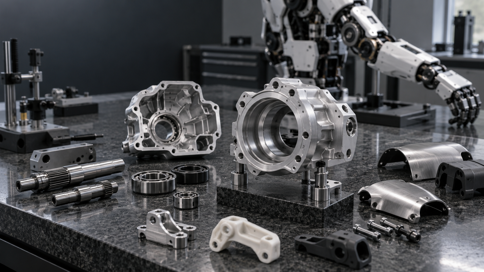
For Humanoid Robot Parts Manufacturing, Start by Breaking Down Functions, Not by Selecting Equipment
A joint module may encounter the following situation: the housing profile, bearing bore diameter, and mounting hole dimensions all pass inspection individually, yet assembly results in bearing edge loading, a binding reducer locating pilot, or difficulty aligning the motor shaft. The problem usually does not lie in any isolated dimension, but in inconsistent datums: the bearing bore is aligned to the housing profile, the reducer mounting face is machined relative to an as-received blank surface, and the motor locating hole is established in another setup. Individual dimensions falling within their tolerance zones does not mean that the relationships among the hole patterns, end faces, and axes are acceptable.
Therefore, humanoid robot parts manufacturing should not begin with the question of “3-axis or 5-axis.” Instead, first determine the function of each part and the consequences of its failure, then translate those functions into critical characteristics that can be manufactured and inspected.
| Load-Bearing Structures | Torso frames and joint housings | Stiffness, load paths, and weight | Thin-wall deformation and localized crushing |
| Transmission and Positioning | Shafts, bushings, and bearing housings | Coaxiality, mating surfaces, and end-face runout | Datum transfer, heat-treatment deformation |
| Connection and support | Flanges, brackets, mounting plates | Hole positions, perpendicularity, contact surfaces | Hole-pattern drift caused by multiple setups |
| Exterior protection | Covers, panels | Weight, profile, surface quality | Warping, uneven seams |
| Wiring harness integration | Clips, guides, protective sleeves | Routing space, corner radii, insulation and assembly clearances | Interference, wire chafing, incorrect assembly orientation |
During the review, information can be recorded in the order of function—critical characteristics—manufacturing risks. For example, the function of a bearing housing is to provide stable support for a rotating shaft system. Its critical characteristics are therefore not all of its overall dimensions, but rather the bore diameter, coaxiality, end-face perpendicularity, and mating surfaces. The corresponding risks include clamping deformation, tool deflection, and inconsistent inspection datums. Only after these inputs have been clearly defined can materials, blanks, CNC machining, sheet metal fabrication, and 3D printing routes be compared on a sound basis.
How to Choose a Manufacturing Process for Humanoid Robot Parts: CNC Machining, Sheet Metal Fabrication, 3D Printing, or Forming
Process selection begins with the function of the part, followed by production volume and the frequency of design revisions. Joint housings require control of bearing bores, mounting surfaces, and hole-pattern relationships, so CNC machining is typically evaluated first. If a protective cover is primarily intended to provide lightweight, low-cost coverage, the same process route does not need to be applied. Humanoid robot parts are often manufactured using a combination of processes rather than requiring every part in the robot to be made with a single type of equipment.
Process Selection Table for Humanoid Robot Parts Manufacturing
| CNC Machining | Joint housings, bushings, flanges, multi-sided brackets, and parts with stringent fit requirements | Suitable for controlling bores, locating shoulders, and datum surfaces; pay attention to fixturing, tool accessibility, and mating dimensions after surface treatment | Suitable for prototypes and low-volume production; design revisions generally do not require new tooling, but complex fixturing increases the per-unit cost |
| Sheet Metal Fabrication | Enclosures, mounting plates, wire harness brackets, and developable bent structures | Focus on checking bend radii, hole-to-edge distances, welding distortion, and hole position relationships after bending | Suitable for rapid iteration; the design should minimize unnecessary welds and special tooling |
| 3D Printing | Complex internal flow channels, lightweight geometries, early-stage structural validation, and difficult-to-machine geometries | FDM, SLA, SLS, MJF, and DMLS have different limitations in materials, surface finish, and accuracy; critical mating surfaces may still require post-machining | Suitable for low quantities and frequent design revisions; the wall thicknesses and tolerances of printed prototypes cannot be directly carried over to mass-production processes |
| Vacuum Casting | Plastic parts requiring an injection-molded-like appearance, soft and rigid material effects, or multi-part assembly validation | Pay attention to master pattern quality, shrinkage, air bubbles, and post-processing consistency | Suitable for low-volume validation; mold life and repeatability must be confirmed for each project |
| Injection Molding | Plastic housings, covers, and wire harness components with stable designs | Wall thickness, draft angles, gates, sink marks, and insert structures must be addressed early in the design process | Evaluate this option once production volume reaches the economic threshold for tooling; design revisions may require mold modification or a new mold |
A single prototype can use CNC-machined joint interfaces, sheet metal brackets, 3D-printed air ducts, and vacuum-cast housings at the same time. Once the design is frozen, plastic parts with stable production quantities can be evaluated for injection molding. The final manufacturing route should be determined collectively based on 2D drawings, 3D models, material condition, estimated quantities, and inspection requirements, rather than solely on part geometry or per-unit quotations.
Materials and Structures for Humanoid Robot Parts Must Be Evaluated Together
Material selection cannot be separated from load paths and manufacturing structure. In humanoid robot parts manufacturing, aluminum alloys are commonly used for joint housings and connectors that require weight reduction. However, the design must also account for the risk of localized crushing at bearing seats, screw connection areas, and clamping locations. Even if a thin-walled aluminum housing has sufficient static strength, it may still fail due to inadequate stiffness, machining distortion, or repeated assembly and disassembly of threaded connections.
Different Humanoid Robot Parts Require Different Material Properties
Shafts, pins, and wear sleeves typically place greater emphasis on strength, fatigue resistance, wear resistance, and dimensional stability after heat treatment. If heat treatment is performed before finish machining, sufficient removable stock should be reserved; if heat treatment is performed after machining, deformation and subsequent grinding requirements must be evaluated. Stainless steel is suitable for parts requiring corrosion resistance, but cutting loads, tool wear, and thin-wall deformation generally need to be assessed separately. Engineering plastics are suitable for protective covers, insulating supports, and lightly loaded guide components. Key considerations include temperature rise, creep, moisture absorption, crushing at fastening points, and appearance, rather than density alone.
Lightweighting Humanoid Robots Does Not Simply Mean Making Parts Thinner
Effective weight reduction should begin by determining how loads are transferred from the bearing housing to the mounting surface, then using ribs, fillets, and localized thickening to maintain rigidity. Metal inserts can be considered for threaded locations that require frequent assembly and disassembly. Material around holes, press-fit areas, and fastening surfaces should not be thinned by the same amount as non-load-bearing areas. Abrupt increases in thickness should also be avoided at rib intersections to reduce dimensional variation caused by residual stress in the blank, machining deformation, or molding shrinkage.
Tool Accessibility and Fixturing Design for Humanoid Robot CNC Parts
Joint housings and multi-sided brackets often combine deep cavities, narrow slots, internal corners, cross holes, reverse-side steps, and thin walls in a single part. Each additional machining direction may require another setup, realignment, and datum transfer. The deeper the cavity, the longer the tool overhang, making vibration, tool deflection, and surface tool marks more difficult to control. When designing humanoid robot CNC parts, verify toolpaths and the clamping sequence before deciding which features are worth retaining.
Determine the Primary Locating Surface and Process Datums First
Give priority to a surface with sufficient area and rigidity, and with a clearly defined positional relationship to the bearing bores or mounting interfaces, as the primary locating surface. Critical hole patterns should be machined in the same setup whenever possible to reduce hole-axis deviation caused by realignment after flipping the part. If reverse-side steps or multidirectional holes must be machined, secondary locating datums should be defined during model review. Do not rely on cosmetic curved surfaces, blank edges, or sidewalls that have already been thinned for alignment.
Check Tool Diameter, Overhang, and Internal Corner Radii
The internal corner radius determines the usable tool diameter, while cavity depth determines the tool length-to-diameter ratio. Small radii combined with deep cavities generally require long, slender tools, which restrict cutting parameters and are more prone to chatter marks or uncut material. Internal corner radii with no functional differences can be standardized and appropriately enlarged, while narrow, deep cavities included solely for weight reduction can be eliminated. For cross holes, also check the available space for drill entry, chip evacuation, and tool retraction to prevent the hole entrance from being obstructed by ribs or adjacent walls.
Reserve Stable Clamping Areas for Humanoid Robot CNC Parts
Fixtures require planes, steps, or process tabs that can be contacted repeatably. If a thin-walled housing has only curved surfaces available for clamping, the clamping force may deform the part, with the dimensions springing back after unclamping. Stable areas can be reserved for the first and subsequent setups, with process tabs removed last. Do not remove connecting ribs or the blank frame too early. Critical holes, datum surfaces, and most cavities should be completed before temporary rigid connections are removed. The specific clamping allowance and removal sequence must be confirmed with the manufacturer based on the material condition, wall thickness, and tooling.
Tolerances for Humanoid Robot Part Machining Should Be Determined by the Assembly Chain
The starting point for tolerancing a joint module is not “what the machine can achieve,” but which interfaces determine positioning and rotational accuracy as torque is transmitted from the motor through the reducer and bearings to the housing. Bearing bores primarily control fit dimensions, roundness, and coaxial relationships. Reducer locating pilots provide radial positioning. Mounting end faces require control of flatness and perpendicularity to the axis. Motor hole locations should be defined relative to the same assembly datums. Surface roughness specifies requirements for contact, sealing, or rotating surfaces and cannot replace dimensional and geometric tolerances.
Establish Common Datums Before Machining Humanoid Robot Parts
If the bearing bore is dimensioned from the housing profile while the reducer locating pilot is dimensioned from another end face, the assembled shaft system may still be eccentric even if both dimensions pass inspection individually. The primary datum surface, locating pilot, and directional datum should be selected along the actual assembly chain, and critical relationships should then be controlled using requirements such as position, coaxiality, or runout. Tolerance stack-up must also be evaluated. Individually acceptable hole spacing, locating-pilot clearance, end-face thickness, and fastener clearance do not guarantee that the assembled motor shaft and reducer input will remain aligned.
Grade Humanoid Robot Part Tolerances by Function
| Grade | Applicable Characteristics | Drawing and Inspection Priorities |
|---|---|---|
| Class A | Bearing bores, shaft-system relationships, and gearbox locating registers | Clearly define datums, dimensions, and geometric tolerances, and specify practical inspection methods |
| Class B | Motor mounting holes, module mating faces, and interchangeable interfaces | Control assembly boundaries and hole-pattern positions; avoid unnecessarily tightening individual dimensional tolerances |
| Class C | Non-mating external features, clearance grooves, and cosmetic contours | Use general tolerances or profile requirements, with a focus on preventing interference |
Applying tight tolerances to every dimension generally only increases finish machining, slow-feed passes, in-process measurement, and scrap risk, without necessarily improving overall system performance. For Class A and B characteristics, the inspection datums and measuring equipment capabilities should also be verified; tolerances for mating surfaces should not be applied to Class C characteristics. Anodizing, plating, or other surface treatments may also alter bore diameters, locating registers, and thread conditions. The drawing should specify whether critical dimensions are to be inspected before or after treatment. Common industry tolerance values should only be used as preliminary guidance. Final requirements must be confirmed based on loads, bearing or fastener specifications, material condition, assembly method, and actual inspection capabilities.
How to Plan Fixturing and Inspection for Humanoid Robot Part Machining
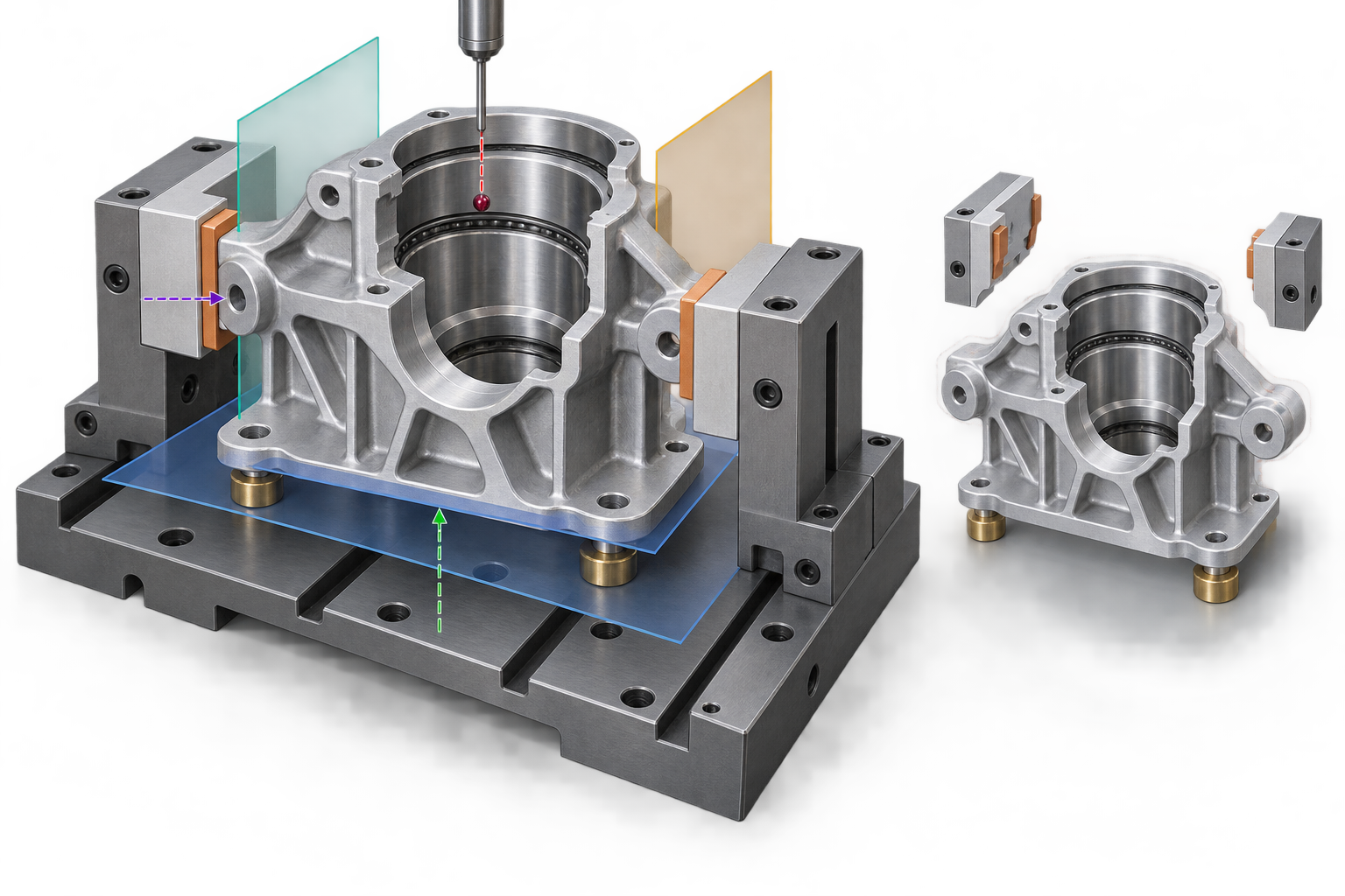
Fixturing and inspection should use the same set of functional datums. If machining is aligned to the edges of the blank, assembly relies on bearing bores and mounting faces, and inspection measures individual dimensions separately, the dimensions may pass inspection while the hole-pattern relationships remain out of tolerance. Before developing the machining process for humanoid robot parts, the primary, secondary, and tertiary datums should be established, and critical hole positions, mounting-face perpendicularity, and coaxial relationships should reference these datums.
Fixturing Risks in Humanoid Robot Part Machining
Thin-walled joint housings may temporarily deform when clamped and spring back after unclamping. Deep-cavity rough machining may also release residual stresses in the blank. The process plan may separate roughing from finishing, leave a uniform machining allowance, and require reinspection in a free state or under a specified clamping force. Reliable locating surfaces and clamping areas should be retained for machining the opposite side, rather than removing all datums in the first operation. Soft jaws are suitable for conforming to regular contours, while dedicated fixtures are suitable for multi-face location or repeat production batches. In both cases, clearance, support locations, and clamping directions must be verified to ensure that pressure is not applied to thin-walled areas.
Inspection Methods for Humanoid Robot Part Machining
Calipers and micrometers are suitable for conventional lengths, thicknesses, and outside diameters, but should not be used alone to evaluate complex hole-pattern relationships. Plug gauges and ring gauges are suitable for quickly checking mating dimensions, but generally do not indicate hole position, roundness, or coaxiality. Coordinate measurement may be evaluated for critical bearing bores, locating registers, and mounting surfaces according to drawing requirements. For complex curved surfaces, freeform surface deviations, or reverse-engineering comparisons, 3D scanning may be considered, but scanning results do not automatically replace dimensional and geometric inspection of mating bores. Dedicated inspection gauges can improve evaluation efficiency for recurring interfaces in batch production, provided that the gauge datums are consistent with the assembly datums.
The inspection plan should also specify the measurement condition, datum establishment method, first-article and sampling inspection logic, and inspection stages before and after surface treatment. Anodizing, plating, or coating may alter bore diameters, contact surfaces, and profile boundaries; the drawing should clearly indicate which characteristics are controlled before treatment and which are accepted in their final condition. For parts prone to deformation, the free state, fixture-constrained state, or assembled state should also be specified to prevent the manufacturer and assembler from evaluating the same dimension under different conditions.
Release Checklist for Humanoid Robot Parts from Prototyping to Low-Volume Production
The fact that prototype parts can be assembled does not mean the process is ready for low-volume production. Before release, the design revision, manufacturing datums, inspection methods, and first-article issues should be closed out item by item to avoid directly replicating practices that depend on an experienced machinist's expertise in subsequent orders.
Pre-Release Inspection for Humanoid Robot Parts Manufacturing
- The revision numbers of the 3D model, 2D drawing, and bill of materials are consistent, and all revised dimensions have been synchronized.
- The material grade, supply condition, heat treatment, and surface treatment requirements are clearly specified rather than only stating the material category.
- Bearing bores, locating registers, and mounting hole patterns use a common datum system, with critical geometric tolerances specified.
- Fixturing assessments have been completed for thin-walled, deep-cavity, and multi-sided structures, and the clamping areas will not damage functional surfaces.
- The effective thread depth, tap-drill depth allowance, tool retraction clearance, and access to cross holes are all feasible.
- Each critical characteristic has a corresponding measuring instrument, inspection gauge, or measurement plan, with the measurement condition before and after treatment specified.
- Issues involving first-article assembly, deformation, and measurement have been entered in the revision log, with clear responsibilities and closure criteria.
Typical Failures to Be Closed Out Before Low-Volume Production Release
| Failure Symptom | Priority Corrective Action |
|---|---|
| The joint housing springs back after unclamping, changing the bore diameter or flatness | Reduce the clamping force, adjust the machining sequence, and evaluate stress relief and the finishing allowance |
| The bearing press fit is too tight, or rotational resistance increases after installation | Review the fit, tolerance zones, bore geometry, and housing deformation after press fitting |
| Mating bores shrink after anodizing, plating, or other treatments | Clearly specify masking, treatment allowances, and final inspection requirements after surface treatment |
| Multiple setups cause hole positions or coaxial relationships to drift | Reduce datum changes and add repeatable locating features or dedicated fixtures |
| Continuing to use the prototyping process leads to uncontrolled per-unit costs | Reassess the blank, operations, inspection gauges, and machining cycle time based on production volume |
During the prototyping stage, additional part reorientations, general-purpose fixtures, or piece-by-piece inspection may be acceptable to speed up design revisions. Once small-batch production begins, key datums, inspection criteria, and the primary process route should be finalized. If the material, surface treatment, or assembly interface changes, the part should be requalified rather than merely updating the 3D model.
Common Issues in Machining Humanoid Robot Parts
The following issues are commonly encountered in joint housings, thin-walled structures, critical hole patterns, and the transition from prototyping to production. Actual decisions should not be based solely on part geometry; assembly datums, material condition, surface treatment, inspection capabilities, and the manufacturer's process capabilities should also be considered.
Do humanoid robot joint housings always require 5-axis machining?
Not necessarily. If critical holes, mounting surfaces, and cavities can be completed by 3-axis machining with appropriate part reorientations, and the datums can be relocated repeatably, a 3-axis approach can generally also be considered. 5-axis machining is more suitable for structures with holes in multiple orientations, complex surfaces, areas that are difficult for cutting tools to access, or where fewer setups are desired. However, the number of machine axes alone does not guarantee accuracy. Tool accessibility, the number of setups, datum-transfer errors, and inspection methods should be compared carefully, followed by confirmation based on the drawing requirements and the manufacturer's capabilities.
How can machining deformation in thin-walled aluminum alloy structures be reduced?
First, avoid thinning large areas to a uniform wall thickness. Retain ribs, fillets, and locally thicker sections along load paths. The process should preserve stable areas for clamping, remove stock in stages, use symmetrical machining wherever possible, and control clamping force and tool overhang. Residual stress in the blank, cutting heat, and surface treatment can also alter the part's shape, so the measurement condition for critical dimensions should be specified. If necessary, schedule reinspection after rough machining, stress relief, or surface treatment. The specific approach should be confirmed based on the material condition, wall thickness, and structural rigidity.
How should tolerances be assigned to bearing bores and mounting holes?
For bearing bores, priority is typically given to controlling the bore diameter, roundness, or cylindricity related to the fit, as well as coaxiality or positional relationships relative to the shaft-system datum. Mounting holes should be classified as locating holes, fastening holes, or ordinary through-holes according to the locating method. Do not assign tight tolerances uniformly to all holes. Establish the assembly datums first, then allocate requirements based on loads, fit types, bearing or fastener specifications, and the tolerance stack-up. Surface treatments such as anodizing and plating may affect bore diameters, so the drawing should also specify masking, machining before treatment, or finish machining after treatment.
What features should be rechecked when transitioning a humanoid robot prototype from 3D printing to CNC machining or injection molding?
When transitioning to CNC machining, recheck tool access directions, internal fillets, deep cavities, narrow slots, cross-holes, clamping surfaces, and datums for secondary setups. Sharp internal corners or enclosed structures that can be produced directly by printing may not be suitable for machining. When transitioning to injection molding, also recheck wall-thickness uniformity, mold-release direction, draft angles, rib and boss proportions, gate locations, shrinkage, and ejection clearance. Material changes can also affect stiffness, threading methods, and dimensional compensation, so the printed model cannot be reused without modification. The final design should undergo DFM review based on the target material, production volume, assembly requirements, and the manufacturer's capabilities.
Key takeaways
- First classify parts by their load-bearing, transmission, positioning, and protective functions, and then select the manufacturing process.
- The hole pattern positions, bearing fits, and mounting end faces of a joint housing should be planned around a common assembly datum.
- Tolerances should be driven by fits and tolerance chains; ordinary overall dimensions should not all be specified to high precision.
- The primary risks associated with thin walls, deep cavities, and multi-face hole patterns typically arise from tool accessibility, the number of setups, and deformation after release.
- Before moving from prototyping to low-volume production, freeze the datums, inspection methods, and critical characteristics—not just the 3D model.



