Why a “recommended wall thickness table” can put a project over budget
Last year, on a sensor housing project, the structural engineer marked the side walls uniformly as 1.0 mm on the drawing, on the grounds that “the minimum wall thickness found online is 1 mm.” When the SLA first article was removed, two side walls tore from the support roots; when switched to SLS, local sink marks appeared on the mating surface, flatness was out of tolerance, and it could not be pressed tight during assembly. The problem was not the number 1.0 mm itself, but that it was treated as an isolated dimension that could be applied across processes.
Wall thickness is never a geometry problem; it is a function of thermal history and toolpath. The same 1.0 mm wall must withstand peel force per layer in SLA, wait for the powder bed to cool in SLS, endure solidification shrinkage stress in DMLS, and is also constrained by nozzle diameter and extrusion line width in FDM. When the process changes, the limiting factor changes, and the range of wall thicknesses that can hold up changes with it.
What is more troublesome is cost. If the wall thickness is too thin, scrap rates and post-processing labor go up; if too thick, material consumption, print time, and cooling cycles all rise together, and injection-molded parts also require a longer packing stage. No one will calculate this for you at the quotation stage. By the time DVT reveals that the structure needs to be changed, the mold or tooling has already been cut, and the rework cost can only be absorbed by yourself.
So the order of judgment cannot be reversed: first determine the process, then determine wall thickness, and finally determine transitions and inspection. Below is a cross-process baseline table first, then a breakdown of failure mechanisms, and finally actionable modeling rules and inspection items.
Cross-process wall thickness baselines: minimum, recommended, upper limit, and dominant limiting factors
Wall thickness is not an isolated dimension that can be looked up in a table and copied directly. If 1.2 mm is written on the same drawing, an SLA part may tear along the layers during removal, a DMLS part may warp due to solidification stress, and an injection-molded part may have sink marks or insufficient filling. The reason is that the wall thickness limit of each process comes from a different physical mechanism: FDM is constrained by nozzle geometry and toolpath, SLA by peel force and resin viscosity, SLS/MJF by heat accumulation and the powder melting window, DMLS by solidification shrinkage stress, and vacuum casting and injection molding by demolding and flow front constraints.
Therefore, the correct approach is to determine the process first, then the wall thickness, and finally the transitions and inspection. The table below gives common industry reference ranges for quickly establishing a baseline for judgment, and is not a guaranteed value for any supplier. The actually achievable wall thickness depends on the equipment model, material grade, print orientation, support strategy, and post-processing method, and must be confirmed item by item with the supplier before quotation.
| Process | Minimum wall thickness (reference) | Recommended wall thickness (reference) | Upper limit (reference) | Dominant limiting factors |
|---|---|---|---|---|
| FDM | ≥ nozzle diameter × 2 (commonly 0.8–1.0 mm) | 1.2–2.5 mm (integer multiples of the nozzle) | No hard upper limit, but >6 mm tends to retain a hot core | Nozzle geometry, toolpath, interlayer bonding |
| SLA/DLP | 0.4–0.6 mm (small parts) | 0.8–2.0 mm | >5 mm shows obvious internal stress marks and shrinkage | Peel force, resin viscosity, post-curing shrinkage |
| SLS | 0.7–1.0 mm | 1.5–3.0 mm | >8 mm heat accumulation causes the core to remain unmelted | Powder melting window, heat accumulation, cooling gradient |
| MJF | 0.5–0.8 mm | 1.2–2.5 mm | >6 mm risk of local sink marks | Heat accumulation, flux distribution, orientation |
| DMLS/SLM | 0.3–0.5 mm (simple shapes) | 0.8–2.0 mm | >10 mm solidification stress warping | Solidification shrinkage stress, support and thermal gradients |
| Vacuum casting | 0.8–1.2 mm | 2.0–4.0 mm | >10 mm shrinkage cavities and bubbles | Demolding, resin flow, exothermic curing |
| Injection molding | 0.6–1.0 mm (depending on material) | 1.5–3.5 mm | >5 mm sink marks and sharply increased cooling time | Flow front, packing, demolding and cooling |
Keep three things in mind when reading the table: First, minimum wall thickness usually means it can be locally formed, not that the structure is reliable; second, the recommended range is a compromise that balances strength, dimensional stability, and cost; third, the upper limit is often easier to overlook than the lower limit—the trapped hot core, sink marks, and warping caused by thick walls only become exposed during assembly. If a part has both thin-wall and thick-wall regions, an abrupt transition in wall thickness is more dangerous than the absolute value, and this will be discussed separately later.
What happens if it is too thin, and what happens if it is too thick: failure mechanisms by process
Wall thickness is not an isolated dimension; what it determines is the thermal history and toolpath. Change the process for the same drawing, and the failure mode changes. Below, we break it down along four mainstream routes, and each section comes back to a feature you can point to in CAD.
SLA/DLP: thin walls die from peel force, thick walls die from post-cure shrinkage
In photopolymerization, each layer must be "peeled" off the release film. For thin sheets with wall thickness below 0.6 mm, the pull force at the moment of peeling is enough to make the edges curl or tear, especially in cantilevered structures. Features to check: suspended thin sheets, slender ribs, sharp corners. Conversely, for solid blocks with wall thickness above about 4 mm, the internal resin is difficult to fully cure, and uneven shrinkage during post-curing causes flatness to start drifting. Features to check: thick bosses, large cross-section flanges. For such locations, it is recommended to hollow them out and leave drainage holes, rather than relying on thickening to preserve strength.
SLS/MJF: thin walls die from insufficient heat accumulation, thick walls die from trapped hot cores
Powder beds rely on hot-zone sintering; thin walls dissipate heat too quickly, layers do not have time to fuse, and they delaminate as soon as they are snapped apart during part removal; this is especially obvious for columnar or sheet-like features with wall thickness below about 0.8 mm. Thick walls are the opposite: heat accumulates in the core and cannot escape, resulting in local sink marks and undersized dimensions after cooling. Features to check: abrupt thick-to-thin steps, enclosed thick blocks. A common industry practice is to make thick blocks into shells with powder drainage holes, with wall thickness controlled in the 2–3 mm range; the specifics depend on the material and equipment and must be confirmed with the supplier.
SLM/DMLS: thin walls die from solidification stress, thick walls die from residual stress warping
The metal melt pool solidifies rapidly; thin walls have little constraint and are easily bent during cooling; metal sheets with wall thickness below about 0.4 mm often deform during part removal and support removal. Thick walls, because of the large temperature difference between layers, concentrate residual stress, and long thick-walled parts warp along their length. Features to check: long thin plates, large-area thick plates. Countermeasures are usually to change orientation, add supports, or split thick walls into thin-walled structures with reinforcing ribs.
FDM: thin walls die from nozzle geometry, thick walls die from heat buildup
In FDM, the outer wall width is limited by the nozzle diameter. When the wall thickness is not an integer multiple of the nozzle, the slicing software adds a thin strip, and strength drops sharply. Wall thickness below the nozzle diameter (commonly 0.4 mm) basically cannot produce a stable contour. Thick walls, because the nozzle repeatedly travels over the same area, accumulate heat, causing surface wrinkling and dimensional expansion. Features to check: non-integer-multiple wall thickness, continuous thick regions. Making the outer wall an integer multiple of the nozzle is more effective than increasing infill density.
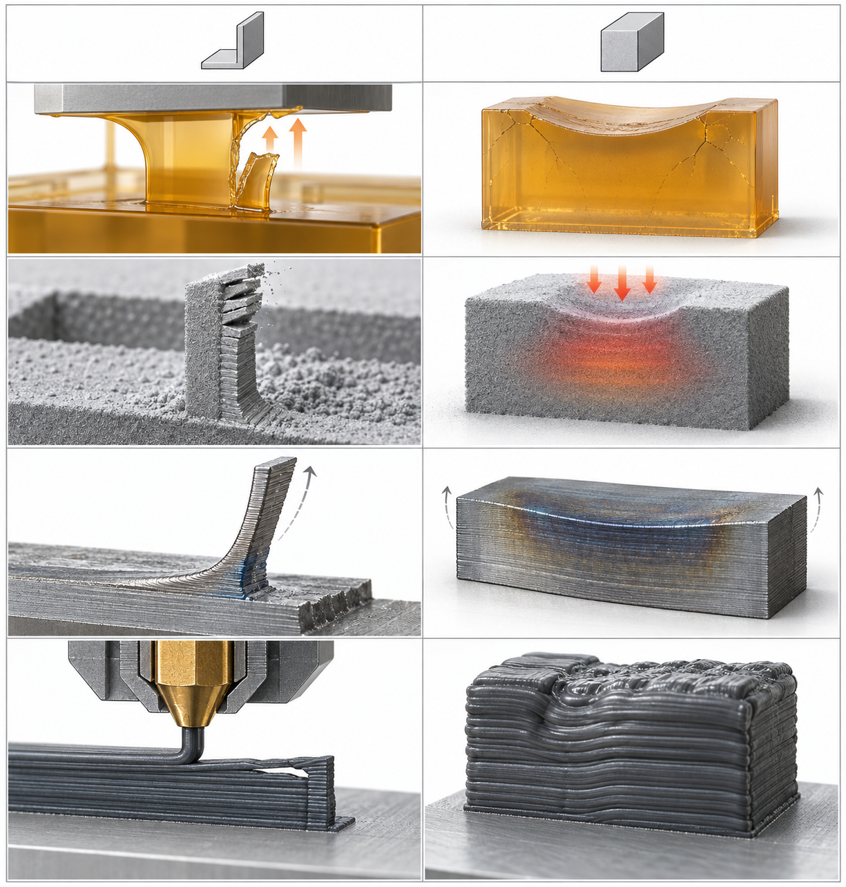
Remember these four groups of failures as one sentence: thin walls fear force, thick walls fear heat. During drawing review, first ask "is this feature thin or thick," then ask "does this process fear force or heat," and the direction becomes clear.
Actionable modeling rules: nozzle integer multiples, transition ratios, internal fillets
Once wall thickness is set, three things on the drawing truly determine success or failure: how much wall thickness to use, how to transition between thick and thin, and how to handle corners. Changing these three things during modeling costs almost nothing; changing them after the first article comes out means rescheduling production. The four rules below can be applied directly to your CAD.
A failure case: a complete review from drawing to first-article inspection
Corrective actions: three changes, no added cost
- Add a transition: change the 1.2→4 mm step into a tapered transition, with the transition length at least 3 times the thickness difference (i.e., ≥8.4 mm), to smooth out the thermal gradient.
- Change orientation: rotate the assembly face 90° so it no longer sits flat against the powder bed bottom, reducing heat accumulation and support contact at the bottom.
- Local thinning: hollow out the thick region into a 2 mm wall plus ribs, bringing the thick-to-thin ratio under 2:1.
Exceptions and boundaries: elastomers, metals, transparent parts, microfluidics
The wall thickness rules in the previous sections assume rigid plastics, conventional orientation, and room-temperature use. Once the material changes to an elastomer, or the part needs to transmit light, carry flow, or withstand high temperatures, the same set of numbers will backfire on you. This section clarifies which scenarios the earlier recommendations do not apply to, and which direction to correct toward.
Elastomers: wall thickness should increase, not decrease
For elastomers like TPU and TPE, thin-walled parts can buckle during printing due to their own weight and nozzle drag, and deform as soon as they are pulled during removal. The "minimum wall thickness" experience for rigid plastics needs to be raised here: a common industry practice is to set the minimum wall thickness for elastomers at 1.5–2 times that of rigid parts, depending on Shore hardness—the softer the material, the thicker it needs to be. But it can't be thickened indefinitely; thick-walled elastomers tend to form unfused areas or bubbles internally, and compression set worsens. If a part needs to be both soft and thin, it's usually better to switch to vacuum casting or adjust the structure (add ribs, change the cross-section) rather than forcing it through printing.
Metal DMLS: thin walls are limited by solidification stress
For thin walls in metal powder bed fusion, the limitation isn't the nozzle but solidification shrinkage stress. When wall thickness is below about 0.4–0.6 mm (depending on alloy and orientation), warping or even cracking easily occurs during printing, because as each layer's melt pool cools and shrinks, the thin wall lacks sufficient cross-sectional stiffness to resist tensile stress. Thick walls are the opposite: heat accumulates in the core, easily producing balling, porosity, and residual stress. Wall thickness design for metal parts must consider both print orientation and subsequent support removal—thin walls near support surfaces may crack when supports are removed. If a part must be thin-walled metal, it's usually recommended to redesign it as a ribbed structure, turning "thin wall" into "thin wall + reinforcing ribs," rather than simply reducing thickness.
Transparent parts and microfluidics: both thick and thin come at a cost
For transparent parts (SLA clear resin, PC-type), when wall thickness is too large, internal residual stress and layer lines are magnified under transmitted light, appearing hazy with flow marks. To transmit light, wall thickness is usually kept within 2–3 mm, combined with post-processing (sanding, polishing, clear coating). Microfluidic chips are the opposite: the channel wall thickness can't be too thin, otherwise the channel deforms under pressure and changes flow resistance; but walls that are too thick also affect optical detection. A common practice is to set the channel wall thickness at 1–2 times the channel width, and specify channel dimensional tolerances and surface roughness requirements on the drawing, rather than just writing a single wall thickness number.
One-sentence test: wall thickness rules are a function of process and material, not a universal constant. Change the material, change the process, change the post-processing, and you must re-verify. When unsure, write the part's application, loads, and light transmission or sealing requirements into the RFQ description, and let the process provider give targeted wall thickness recommendations—far less hassle than guessing in CAD yourself.
Inspection, procurement, and tolerances: how to measure wall thickness and how to specify tolerances
During first-article inspection, wall thickness is often the item most prone to disputes. Clamp the calipers, read 1.18 mm, drawing says 1.2±0.1, looks acceptable; but the assembly face is warped 0.3 mm, and the whole batch is scrapped. The problem isn't the calipers, it's that the measurement datum and tolerance allocation are not aligned with function. Thin-walled parts are affected by clamping force, temperature, and post-processing; caliper contact pressure alone can make elastomer readings 0.05–0.15 mm low. Common industry practice: for rigid plastic parts, use calipers or micrometers, with measurement points avoiding gates, weld lines, and support remnants; for elastomers or thin-walled curved parts, switch to non-contact methods (vision systems, laser scanning) or CT to avoid contact deformation. CT can provide a wall thickness distribution contour map in one pass, suitable for verifying transition zones and internal cavities, but it is costly and slow, usually only used for first articles or disputed parts.
Measurement datum and tolerance relaxation logic
Before specifying wall thickness tolerances on a drawing, ask: is this thickness a functional dimension or a reference dimension? If wall thickness only affects stiffness and not assembly, the tolerance can be relaxed to ±10% or even wider; if wall thickness determines snap-fit interference or channel cross-section, then it needs to be tightened to ±0.05–0.1 mm. For thin-walled parts (wall thickness less than 1.5 mm), symmetric tolerances are not recommended, because thickness deviation in printing or injection molding is usually unidirectional toward thin—material shrinkage, uneven cooling, and nozzle path compensation all make actual values smaller than nominal. A more practical approach is to specify a unilateral lower limit: nominal 1.2 mm, marked "minimum 1.1 mm," with no upper limit control, to prevent suppliers from thickening to hit the upper limit and causing warping. For measurement datum, prioritize the assembly face or locating holes, not the print platform face—the latter is affected by support remnants and first-layer compression, with poor repeatability.
Information checklist that must be attached when requesting a quote
If wall thickness issues aren't clearly stated at the quotation stage, rework is guaranteed in mass production. When requesting quotes from suppliers, attach at least the following information, otherwise they can only quote based on default wall thickness, and later drawing changes will cost extra:
- Process and material: FDM/SLA/SLS/MJF/DMLS or injection molding, material grade or equivalent grade. The same wall thickness has completely different manufacturability under different processes.
- Print/forming orientation: mark the datum face on the drawing or require isotropy, otherwise the supplier will orient it to minimize supports, and thin-wall strength may be only 60% of nominal.
- Critical wall thickness and tolerances: mark functional wall thickness and reference wall thickness, note the measurement datum and whether unilateral thinning is allowed.
- Post-processing requirements: support removal, sandblasting, machining, polishing, annealing. Sandblasting thins outer walls, machining clamping deforms parts—these must be stated before quoting.
- Acceptance method: caliper sampling, full CT inspection, or assembly verification. The acceptance method directly determines the supplier's process window and quote.
There's one more often-overlooked point on the procurement side: thin-walled parts should not be quoted by volume. Reducing wall thickness from 2 mm to 1 mm saves half the material, but print time, support volume, and scrap rate often increase, so the unit price may go up rather than down. If a supplier quotes only by weight, thin-walled parts tend to be quoted low, then made up later through "out-of-tolerance" claims. A more robust approach is to require per-part pricing with wall thickness acceptance criteria noted, and write the inspection method and tolerances into the order attachment. To quickly compare wall thickness manufacturability and quotes across different processes, you can use the 3D printing quote entry or classic quote, uploading the drawing, orientation, and tolerance requirements together to reduce back-and-forth confirmation.
Frequently Asked Questions (FAQ)
The following questions come up in almost every drawing review. The answers depend on equipment, material, and orientation; what's given here is a judgment framework, not a guaranteed value.
Can infill percentage replace wall thickness? If I set infill to 80%, do I not need to worry about wall thickness?
No. Bending and tensile loads are mainly borne by the outer walls; infill only affects internal support and compressive stiffness. When outer walls are too thin, even at 100% infill, the part will still crack along layer lines during removal, assembly, or drop. Common practice is to first set outer wall thickness to the process-recommended range, then use infill to tune stiffness and weight; doing it the other way around often consumes material without solving the strength problem.
What are the risks of exceeding the upper wall thickness limit? Isn't thicker stronger?
Not necessarily. Thick walls in SLS/MJF retain heat, causing slow core cooling, localized sinking, and warping; in SLA they increase peel forces, making tearing likely during removal; in DMLS, abrupt thick-to-thin transitions concentrate solidification stress and may crack. Thick walls also increase material and time costs. If the structure needs stiffness, prioritize ribs, shells, or cross-section changes rather than blindly thickening.
How to ensure wall thickness uniformity? What should be marked on the drawing?
First control the thick-to-thin ratio; it's recommended that adjacent region thickness differences not exceed 3:1, and transition length be no less than 3 times the thickness difference. On the drawing, besides nominal wall thickness, note the flatness or fit dimensions of critical assembly faces, and state orientation and post-processing requirements. Uniformity is ultimately confirmed by first-article inspection, commonly with calipers, ultrasonic thickness gauges, or CT; measurement datums for thin-wall regions must be clearly stated, otherwise the data won't match up.
Can the same drawing be used for FDM, SLA, and SLS simultaneously?
The geometry can be shared, but wall thickness cannot be copied over. FDM is limited by nozzle diameter, so outer walls should be integer multiples of the nozzle; SLA is limited by peel forces, so the thin-wall lower limit is stricter; SLS needs no supports but has significant heat accumulation, so the thick-wall upper limit is more sensitive. When quoting across processes, specify process, material, and orientation separately, and let suppliers evaluate by their own rules, rather than using one set of wall thicknesses for all.
How are thin-walled parts quoted? Why do different suppliers vary so much?
Differences in quotes for thin-walled parts usually come from three places: support and post-processing labor hours, scrap rate, and inspection requirements. When the wall thickness approaches the lower process limit, the probability of damage during removal and rework rises, and suppliers factor that risk into the price. When requesting a quote, include the process, material, orientation, critical dimensions, and inspection method so that quotes are comparable. Specific prices and lead times are subject to supplier evaluation; no guaranteed values are given here.
Key takeaways
- Determine the process first, then the wall thickness: for the same drawing, changing the process can make the minimum wall thickness differ by 2–3 times, so wall thickness must be reviewed in conjunction with the process.
- Thin walls: look at peeling and buckling; thick walls: look at hot cores and sink marks: if too thin, first check supports and part removal orientation; if too thick, first check heat accumulation and post-processing.
- Wall thickness transitions are more likely to cause problems than absolute wall thickness: abrupt step changes are breakpoints in stress and cooling rate, and the transition length is recommended to be no less than 3 times the thickness difference.
- For FDM outer walls, use integer multiples of the nozzle; adding shells is more cost-effective than adding infill; elastomers and transparent parts should be thickened according to the opposite rules.
- For first-article inspection, measure wall thickness uniformity and critical cross-sections first, then discuss dimensional tolerances; tolerances for thin-walled parts should be relaxed and the measurement datum noted.



