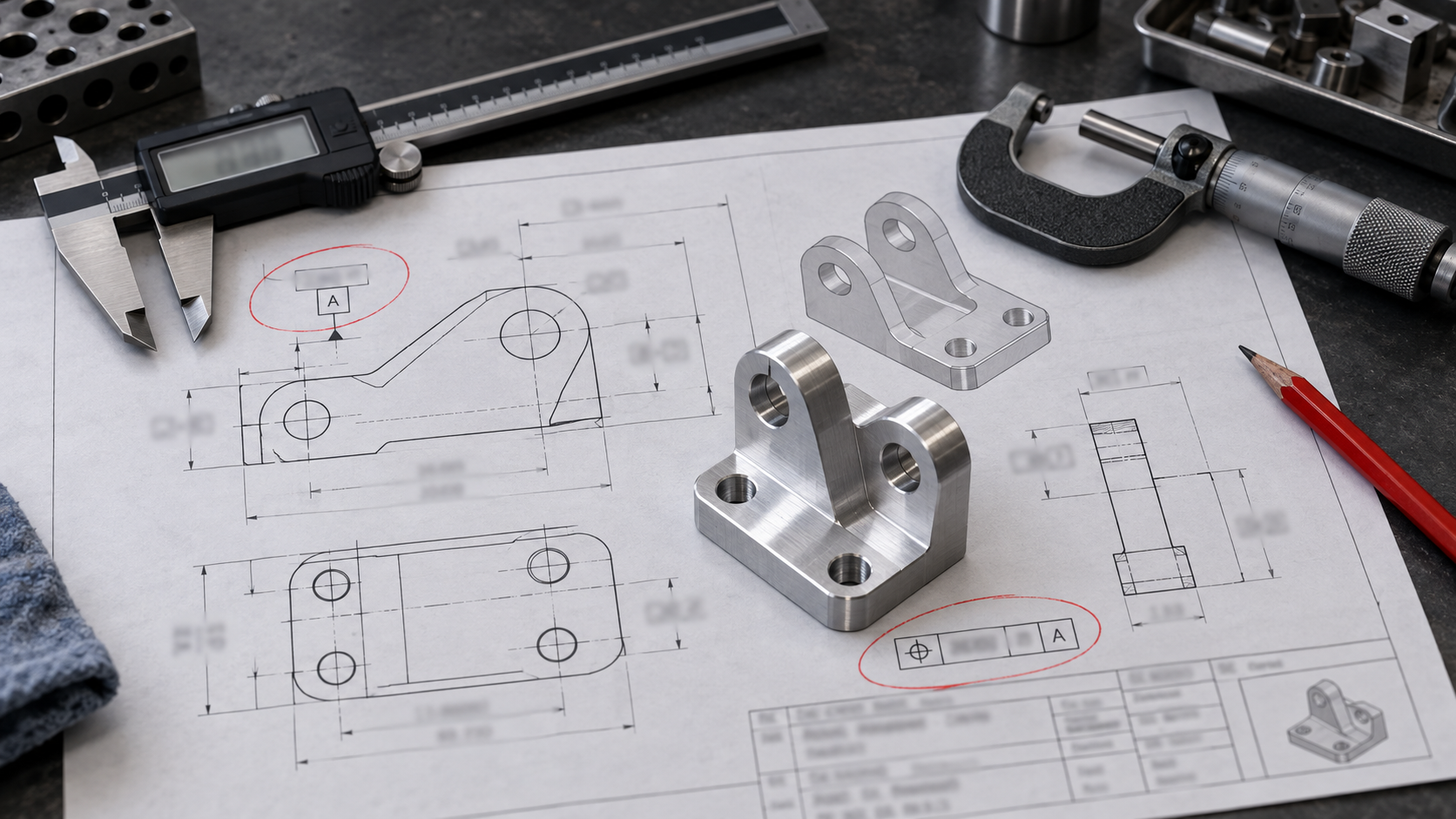
Conclusion first: for robot structural part drawings, the problems are mostly in datums and unspecified requirements
When reviewing robot structural part drawings, don't stare at the dimensional tolerance bands first. Look at two things first: whether datums are specified and on which face they are placed; whether unspecified requirements have a fallback. Once these two are settled, dimensional tolerances become meaningful; if they are wrong, all the later ±0.05 is empty talk. The reason is not complicated—joint parts go through multiple processes such as turning, milling, grinding, and wire cutting, and every setup change changes the datum. If the datum on the drawing falls on a blank surface, a thin wall, or a non-machined surface, the machining datum and the measurement datum will not match. At quoting, the only option is to estimate by the most conservative route, and at inspection there is no way to judge whether it is acceptable.
This rule holds for joint parts with multiple mating surfaces and multiple processes: reducer flanges, bearing seats, and interfaces at both ends of the arm body. If even one datum is ambiguous, coaxiality and position tolerance cannot be converted. The cases where it can be relaxed are also clear: single-piece prototypes, non-load-bearing decorative parts, and purely shape-verification parts—for these, a looser datum and no unspecified requirements usually do not affect assembly, but the drawing must note "prototype part, geometric tolerances not assessed"; otherwise the quotation provider will still quote as for a production part.
Datums and geometric tolerances: one wrong callout changes both the number of setups and scrap judgment
Which face the datum symbol falls on directly determines three things: how many times the part must be set up, how the inspection fixture is designed, and which datum is used to judge when out of tolerance. Robot structural parts are mostly multi-face mating parts, and the cost of a wrong datum is usually not scrapping a single piece, but inconsistent inspection criteria for the entire batch.
Datums should be selected on machined surfaces, not on blank surfaces or thin walls
A common practice is to mark the datum on the final mounting face, but if the drawing marks it on a cast blank surface or an unmachined welded surface, the machinist can only establish a datum first and then transfer it, adding an alignment step, and the position tolerance must also absorb this transfer error. Thin-walled parts are even more troublesome—the datum face itself rebounds due to clamping force, and measurement results drift with the clamping state. It is not rare for the first article to pass and re-inspection to fail.
| Drawing callout | Shop-floor consequence | How to change it |
|---|---|---|
| Datum A falls on a cast blank surface | Requires alignment first and then transfer; position errors stack and setups increase | Change it to a locating face machined in the first operation, or note "datum face must be machined" |
| Coaxiality callout on the outer diameter of a thin-walled sleeve | Clamping deformation causes unstable measurement values and disputes over judgment | Change the datum to the inner bore, give the outer diameter a radial runout, and note the measurement state |
| Position tolerance has no datum specified, only the tolerance value | Different inspectors use different datums, leading to inconsistent judgment results | Complete the A/B/C datum system and specify the datum order |
| Perpendicularity datum selected on a freeform surface | Cannot seat stably; the inspection fixture cannot be made | Select a plane or cylindrical surface as the datum instead; use the curved surface only as a reference |
The measurement datum must be consistent with the machining datum
During review, ask item by item: can this datum face be clamped during machining and supported during inspection? If the answer is no, the drawing needs additional notes, for example "use machined face A as datum," "inspect in the free state," or "re-inspect after stress relief." These notes do not affect the dimensions themselves, but they determine whether the quote includes stress relief, secondary setups, and dedicated inspection fixtures. If not specified, the machinist usually quotes by the most conservative route, and both price and lead time are pushed up.
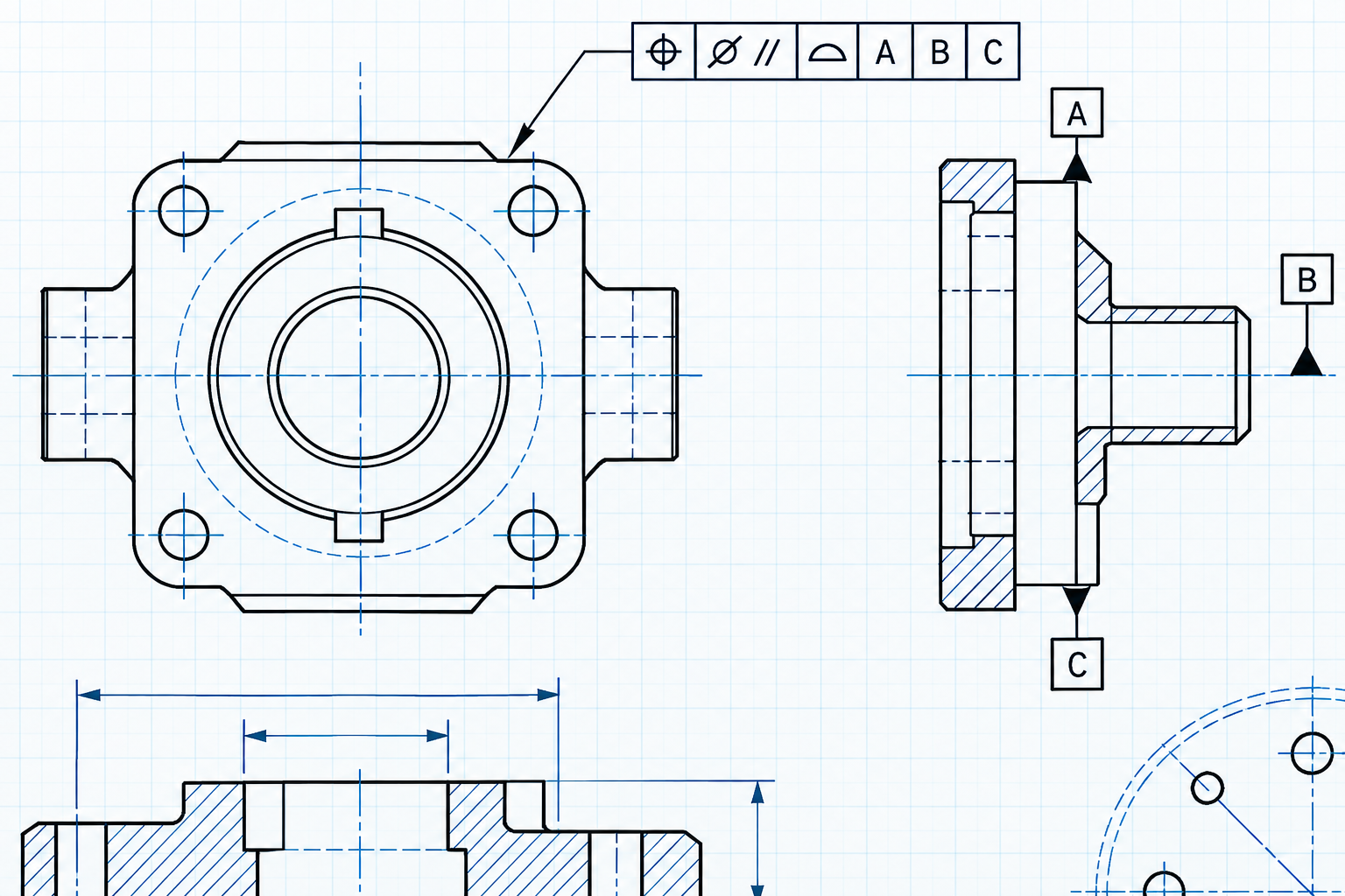
Mating surfaces and non-mating surfaces: which tolerances are worth tightening and which only add cost
On robot structural parts, the only faces that truly need tightening are usually three types: bearing bores, reducer mounting flanges, and guide rail/slider mounting faces. For other freeform surfaces, outer contours, and non-load-bearing ribs, tightening the tolerance by one grade may increase machining costs, yet the assembly effect will be imperceptible. The criterion is simple—does this face participate in locating or transmitting force. If it does, discuss the fit nature; if not, follow general tolerances.
| Feature | Typical fit | What the drawing should specify | Cost of tightening |
|---|---|---|---|
| Bearing bore (inner ring press-fit) | Interference/transition | Bore tolerance zone, cylindricity, roughness Ra | Requires fine boring or reaming, may add a setup |
| Reducer output flange face | Locating + bolt fastening | Flatness, position, bolt hole pitch circle | Flatness must be controlled to avoid warping |
| Linear guide mounting face | Locating datum | Parallelism/coplanarity, mounting hole position | Both rails must be machined in the same operation or match-ground |
| Outer contour/decorative face | Non-fit | General tolerances suffice | Tightening yields essentially no benefit |
Interference, clearance, locating: different sensitivities
Interference fits are most sensitive to the size zone and cylindricity. If the bore is slightly oversized, press-fit force is insufficient; if ovality is out of tolerance, the bearing inner ring is squeezed and deformed after pressing, causing abnormal noise or temperature rise during operation. Clearance fits are sensitive to the size zone but tolerate roughness somewhat more. Locating fits (such as flange spigots) fear position and perpendicularity the most, not a single bore diameter. Writing these three types as the same tolerance grade on a drawing is the most common waste.
A real case on a machined part: a joint housing bearing bore was marked φ40H7, but cylindricity was not specified. After turning, measured ovality was about 0.02; press-fitting felt normal, but after a week of operation, low-frequency abnormal noise appeared. Disassembly revealed the bearing outer ring was unevenly squeezed. The fix is not to tighten H7 further, but to add cylindricity (e.g., 0.008) on the drawing and note roundness sampling before press-fitting. Such problems cannot be solved by tightening dimensional tolerances; they must be written as geometric tolerances.
Thin walls, slender arms, and fillets: where deformation comes from and how to specify it on drawings
The most common deformation in slender arms is not that the machining center "cannot hold tolerance," but that residual stress redistributes during material removal. If the drawing only says "stress relief," the supplier cannot determine whether it goes before roughing, after roughing, or after finishing, so the quote can only be based on the most labor-intensive sequence. A more executable wording splits the stages: rough machining leaving 0.5–1 mm allowance → stress relief (commonly natural aging or vibration/thermal aging, depending on material) → semi-finishing → finishing. Whether it must be specified depends on two criteria: whether the length-to-diameter ratio exceeds about 5:1, and whether key fit faces are near the area of most concentrated material removal. If both are met and it is not specified, the cost of later straightening and rework is usually higher than one aging step.
Wall thickness and ribs: specifying "minimum wall thickness" is more useful than "as thin as possible"
"Reduce weight as much as possible while ensuring strength" is an unexecutable note. During review, change it into three quantifiable items: minimum wall thickness value (commonly 1.5–3 mm for aluminum parts in the industry, depending on height and area, to be confirmed per drawing), rib height-to-thickness ratio (rib height generally not exceeding 3–4 times rib thickness, otherwise milling deflection occurs and the root is prone to vibration), and opening width between ribs (must allow tool entry; narrow slots can only be EDM'd, and cost jumps a tier). If these three are not specified, the process can only conservatively thicken, and the weight target automatically fails.
Unspecified fillets and sharp corners: consequences are edge chipping and stress concentration
Assuming "the smaller the better" for unspecified internal fillets is wrong. Tool radius determines how small a corner can be cleaned: an R3 internal corner can be done with a φ6 tool, while below R1 often requires a smaller tool and reduced feed, and steps are easily left at the root. More troublesome is specifying a sharp corner at the root of a load-bearing arm—the stress concentration point lands directly near the fit face, affecting fatigue life. The fix: give a general rule in the drawing notes, such as "unspecified internal fillet R2, transitions R3," and separately mark positions that truly need sharp corners with their purpose noted. Whether to relax depends on whether that location bears cyclic loading; decorative or non-load-bearing areas can be relaxed, but joint load-bearing areas are not recommended.
Material condition and blank: the most common source of quotation deviation
For the same drawing, if it only says "45 steel," quotes can differ by a lot. The reason is not machining hours, but the blank: whether it is directly turned from bar stock, a forging with allowance, or a casting with black skin. The three routes differ in material cost, number of setups, rough machining allowance, and inspection requirements. If the drawing does not specify material condition, the quoter can only quote on the most conservative assumption—usually forging or bar stock with allowance, preferring to leave extra.
Blank form determines the machining route, not the other way around
There are three common blank types for robot structural parts: bar stock suits rotational parts and regularly sized arm segments; forgings suit joint seats with high loads and varying cross-sections; castings suit bases with complex shapes and slightly larger batches. Bar stock has small allowance and fast loading, but limited shapes; forgings save material and improve flow lines, but have long procurement cycles and incoming consistency must be confirmed; castings form complex contours in one piece, but black skin and blowholes may force datum faces onto the blank, making fixturing unstable during machining.
What should be added to the drawing is not something like "forging recommended," but material standard number, supply condition (annealed/normalized/quenched and tempered), whether splicing is allowed, and whether black skin may remain. If any of these four is missing, the quoter must make assumptions, and the direction of assumption is usually conservative.
Unspecified heat treatment and inspection: the quoter can only quote to the strictest requirement
The drawing says "quenching and tempering" but does not give a hardness range, so when quoting it is calculated as full quenching and tempering; it says "non-destructive testing when necessary" but does not give a standard, so when quoting it is estimated at the strictest level. This is not the quoter deliberately adding cost; it is that unspecified requirements cannot be priced, so only the upper limit can be taken. Conversely, if the part really does not need quenching and tempering, then clearly state "heat treatment not required" on the drawing or note only stress relief, and the quote can immediately come down.
- Material standard number: GB/T 699, GB/T 3077, or another, and whether the grade is followed by a condition code
- Blank form: bar stock, forging, casting, plate, and whether welded assembly is allowed
- Heat treatment: whether quenching and tempering is required, hardness range, stress relief requirements, aging requirements
- Non-destructive testing: whether required, standard, level, acceptance criteria
- Ownership of allowance: whether black skin surfaces and non-machined surfaces may be retained, and who is responsible for cleaning them
The common industry practice is: at the prototype stage, machine directly from bar stock or plate to save mold and forging lead time; after the batch reaches a certain quantity, then evaluate forgings or castings. But this switch point varies by part, and there is no universal number; it must be calculated separately based on load, batch size, and material utilization, and decided together with process during drawing review.
The inspection plan must be set at the drawing stage: CMM, gauges, and first article
The inspection method directly determines whether there is a "measurement cost" item in the quote. If the drawing only says "inspect to drawing," the quoter will either quote on the most conservative assumptions or discover after machining that it cannot be measured—both outcomes make the delivery schedule look bad.
Which features are written for CMM, and which use gauges
| Feature type | Recommended inspection method | What should be written on the drawing |
|---|---|---|
| Multi-hole interrelated dimensions (position tolerance, hole group spacing) | CMM | Datum system, position tolerance, measured feature numbering |
| Shaft-hole fit diameter, depth | Inside micrometer / plug gauge | Size band, cylindricity, roughness |
| Flatness, parallelism, large-area mating surfaces | Surface plate + feeler gauge / CMM | Flatness tolerance, inspection surface range |
| Free-form surfaces, appearance surfaces | First article + template / 3D scan comparison | Allowable deviation range, comparison datum |
| Threads, counterbores | Thread gauge, visual + caliper | Thread class, counterbore depth tolerance |
CMM is suitable for features with many spatial interrelated dimensions; for a single hole diameter, a plug gauge is faster and cheaper. Write "which features must have CMM reports" into the drawing so the quoter can include measurement labor hours; if not written, only routine sampling inspection is assumed by default.
Reverse criterion: which parts do not need CMM
Single-piece prototypes, non-mating decorative parts, and prototype parts used only for assembly verification can be confirmed with calipers + first article. At this point, forcing a "full-dimension CMM report" will only drive up the unit price without improving the assembly result. The criterion is: will the deviation of that feature cause assembly failure or functional abnormality. If not, CMM is not necessary.
First article confirmation: clearly state scope and acceptance criteria
First article confirmation is not "make one and take a look." The drawing should note which features the first article must cover, which measuring instruments are used, and which tolerance is the basis for acceptance. For batch parts, the sampling ratio and Cpk requirements for critical dimensions (if applicable) should be clearly stated. When this information is missing, the quoter usually quotes "full inspection for first article + sampling inspection for batch," which is on the high side.
If the inspection plan is set early, measurement datums and clamping space can be reserved during machining. If it is set late, the part may be finished before discovering that the datum has been cut away, and only 3D scanning can be used to reverse-engineer it—one more process and one more cost.
Review checklist: go through item by item from drawing to pre-quote
Compress the criteria from the previous sections into a printable checklist. Give each item a judgment criterion: pass (can be quoted directly), needs confirmation (ask design or engineering one question), needs modification (if not changed, rework or scrap will result). Review in order from greatest impact to least; do not start with dimensional tolerances.
The value of a checklist lies in its order, not in the number of items. Base and unspecified requirements come first, which can eliminate most quotation deviations; dimensional tolerances are checked item by item at the end. Once the entire checklist is completed, the quoting party receives a drawing that is machinable, inspectable, and reproducible, rather than an intent that requires back-and-forth clarification.
Frequently Asked Questions (FAQ)
The following questions appear most frequently in drawing reviews and inquiries for robotic structural parts. The answers provide judgment criteria, not guaranteed values; the specific drawing annotations and the technical agreement confirmed by both parties shall prevail.
If the drawing does not specify unspecified tolerances, what does the machinist follow?
Follow the general unspecified tolerance standards. A common practice is to use GB/T 1804 or ISO 2768 m class for linear dimensions, and the corresponding unspecified grades for geometric tolerances. However, for features with fitting relationships such as robot joint parts and guide rail surfaces, unspecified tolerances cannot be relied upon as a fallback—unspecified tolerances only ensure "it can be assembled," not coaxiality or consistent clearance. If something is not specified on the drawing but does affect assembly, it should be added during the drawing review rather than left for the machinist to guess.
Is it safer to specify more geometric tolerances?
No. Each additional geometric tolerance adds one more constraint on the clamping datum and one more inspection operation, which affects both the quotation and the delivery time. The principle is: specify only where it affects assembly, motion accuracy, or sealing, and the datum should be placed on a surface that can actually be clamped and measured. If the datum is placed on a rough surface or thin wall, it cannot be measured accurately even if specified, which instead creates disputes.
What is the relationship between surface roughness and fit tolerance?
The two must match. For an interference-fit bearing bore, when the dimensional band is tightened, the roughness usually also needs to be improved; otherwise, the microscopic peaks and valleys of the surface are sheared during press-fitting, causing the actual interference to deviate from the design value. For the locating surface of a clearance fit, the dimensional band and geometric tolerances are more important, and the roughness requirement can be relaxed. Specifying only roughness without the fit type, or only the fit without roughness, can easily cause problems during assembly.
Can prototype drawings and mass production drawings share the same document?
They can be shared, but they must be distinguished on the drawing. The prototype stage uses CNC or 3D printing for single pieces, while mass production may switch to injection molding, die casting, or sheet metal. The draft, wall thickness, fillet, and parting line requirements differ between the two. If the same drawing does not indicate the process and batch, the quoting party can only quote based on the most conservative assumptions, or quote based on the prototype process and then modify the drawing for mass production, which easily leads to rework in between. It is recommended to manage prototype and mass production drawings as separate versions.
What scope should the inspection report cover?
It depends on the part's application. Key fitting features (bearing bores, flange locating surfaces, guide rail mounting surfaces) usually require a first article full-dimensional plus geometric tolerance report, using a CMM or dedicated gauges; for non-fitting freeform surfaces and appearance surfaces, first article confirmation plus sampling inspection is generally sufficient. The inspection scope should be written into the drawing or technical agreement; otherwise, only routine dimensional sampling inspection is performed by default. Whether to use a CMM and which gauge to use should be confirmed with the machinist before quoting, because it directly affects the quotation composition.
Key takeaways
- For geometric tolerances, look at datums first: if a datum is placed on a non-machined surface or a thin wall, it effectively counts setup error directly into the part. Change it to a machinable machining datum before discussing precision.
- Mating surfaces (bearing bores, reducer flanges, guide rail mounting faces) are worth tightening; non-mating freeform surfaces should follow unspecified tolerances—tightening them only increases measurement labor and disputes over scrap judgments.
- For slender or thin-walled parts such as arm bodies and joint seats, the drawing must clearly specify stress relief/aging requirements; otherwise, deformation after rough machining will only show up during finish machining and assembly.
- Before calling out "mating surface Ra0.8," first confirm the nature of the fit: interference press fit, clearance fit, or positioning only. Different fits have completely different sensitivity to roughness and size bands.
- Before quoting, clarify the material state (forging/bar stock/casting), blank allowance, and nondestructive testing and CMM requirements. Missing this information is a major source of quotation deviation.



